EP0700822B1 - Verfahren zur Begrenzung des Knickwinkels zwischen dem Vorderwagen und dem Nachläufer eines Gelenkomnibusses - Google Patents
Verfahren zur Begrenzung des Knickwinkels zwischen dem Vorderwagen und dem Nachläufer eines Gelenkomnibusses Download PDFInfo
- Publication number
- EP0700822B1 EP0700822B1 EP95112828A EP95112828A EP0700822B1 EP 0700822 B1 EP0700822 B1 EP 0700822B1 EP 95112828 A EP95112828 A EP 95112828A EP 95112828 A EP95112828 A EP 95112828A EP 0700822 B1 EP0700822 B1 EP 0700822B1
- Authority
- EP
- European Patent Office
- Prior art keywords
- force
- trailer
- driving force
- front car
- braking
- Prior art date
- Legal status (The legal status is an assumption and is not a legal conclusion. Google has not performed a legal analysis and makes no representation as to the accuracy of the status listed.)
- Expired - Lifetime
Links
Images
Classifications
-
- B—PERFORMING OPERATIONS; TRANSPORTING
- B60—VEHICLES IN GENERAL
- B60L—PROPULSION OF ELECTRICALLY-PROPELLED VEHICLES; SUPPLYING ELECTRIC POWER FOR AUXILIARY EQUIPMENT OF ELECTRICALLY-PROPELLED VEHICLES; ELECTRODYNAMIC BRAKE SYSTEMS FOR VEHICLES IN GENERAL; MAGNETIC SUSPENSION OR LEVITATION FOR VEHICLES; MONITORING OPERATING VARIABLES OF ELECTRICALLY-PROPELLED VEHICLES; ELECTRIC SAFETY DEVICES FOR ELECTRICALLY-PROPELLED VEHICLES
- B60L7/00—Electrodynamic brake systems for vehicles in general
- B60L7/24—Electrodynamic brake systems for vehicles in general with additional mechanical or electromagnetic braking
- B60L7/26—Controlling the braking effect
-
- B—PERFORMING OPERATIONS; TRANSPORTING
- B60—VEHICLES IN GENERAL
- B60L—PROPULSION OF ELECTRICALLY-PROPELLED VEHICLES; SUPPLYING ELECTRIC POWER FOR AUXILIARY EQUIPMENT OF ELECTRICALLY-PROPELLED VEHICLES; ELECTRODYNAMIC BRAKE SYSTEMS FOR VEHICLES IN GENERAL; MAGNETIC SUSPENSION OR LEVITATION FOR VEHICLES; MONITORING OPERATING VARIABLES OF ELECTRICALLY-PROPELLED VEHICLES; ELECTRIC SAFETY DEVICES FOR ELECTRICALLY-PROPELLED VEHICLES
- B60L3/00—Electric devices on electrically-propelled vehicles for safety purposes; Monitoring operating variables, e.g. speed, deceleration or energy consumption
- B60L3/10—Indicating wheel slip ; Correction of wheel slip
- B60L3/106—Indicating wheel slip ; Correction of wheel slip for maintaining or recovering the adhesion of the drive wheels
-
- B—PERFORMING OPERATIONS; TRANSPORTING
- B60—VEHICLES IN GENERAL
- B60L—PROPULSION OF ELECTRICALLY-PROPELLED VEHICLES; SUPPLYING ELECTRIC POWER FOR AUXILIARY EQUIPMENT OF ELECTRICALLY-PROPELLED VEHICLES; ELECTRODYNAMIC BRAKE SYSTEMS FOR VEHICLES IN GENERAL; MAGNETIC SUSPENSION OR LEVITATION FOR VEHICLES; MONITORING OPERATING VARIABLES OF ELECTRICALLY-PROPELLED VEHICLES; ELECTRIC SAFETY DEVICES FOR ELECTRICALLY-PROPELLED VEHICLES
- B60L7/00—Electrodynamic brake systems for vehicles in general
- B60L7/10—Dynamic electric regenerative braking
- B60L7/18—Controlling the braking effect
-
- B—PERFORMING OPERATIONS; TRANSPORTING
- B60—VEHICLES IN GENERAL
- B60T—VEHICLE BRAKE CONTROL SYSTEMS OR PARTS THEREOF; BRAKE CONTROL SYSTEMS OR PARTS THEREOF, IN GENERAL; ARRANGEMENT OF BRAKING ELEMENTS ON VEHICLES IN GENERAL; PORTABLE DEVICES FOR PREVENTING UNWANTED MOVEMENT OF VEHICLES; VEHICLE MODIFICATIONS TO FACILITATE COOLING OF BRAKES
- B60T8/00—Arrangements for adjusting wheel-braking force to meet varying vehicular or ground-surface conditions, e.g. limiting or varying distribution of braking force
- B60T8/17—Using electrical or electronic regulation means to control braking
- B60T8/1701—Braking or traction control means specially adapted for particular types of vehicles
- B60T8/1708—Braking or traction control means specially adapted for particular types of vehicles for lorries or tractor-trailer combinations
-
- B—PERFORMING OPERATIONS; TRANSPORTING
- B60—VEHICLES IN GENERAL
- B60T—VEHICLE BRAKE CONTROL SYSTEMS OR PARTS THEREOF; BRAKE CONTROL SYSTEMS OR PARTS THEREOF, IN GENERAL; ARRANGEMENT OF BRAKING ELEMENTS ON VEHICLES IN GENERAL; PORTABLE DEVICES FOR PREVENTING UNWANTED MOVEMENT OF VEHICLES; VEHICLE MODIFICATIONS TO FACILITATE COOLING OF BRAKES
- B60T8/00—Arrangements for adjusting wheel-braking force to meet varying vehicular or ground-surface conditions, e.g. limiting or varying distribution of braking force
- B60T8/17—Using electrical or electronic regulation means to control braking
- B60T8/1755—Brake regulation specially adapted to control the stability of the vehicle, e.g. taking into account yaw rate or transverse acceleration in a curve
-
- B—PERFORMING OPERATIONS; TRANSPORTING
- B60—VEHICLES IN GENERAL
- B60T—VEHICLE BRAKE CONTROL SYSTEMS OR PARTS THEREOF; BRAKE CONTROL SYSTEMS OR PARTS THEREOF, IN GENERAL; ARRANGEMENT OF BRAKING ELEMENTS ON VEHICLES IN GENERAL; PORTABLE DEVICES FOR PREVENTING UNWANTED MOVEMENT OF VEHICLES; VEHICLE MODIFICATIONS TO FACILITATE COOLING OF BRAKES
- B60T8/00—Arrangements for adjusting wheel-braking force to meet varying vehicular or ground-surface conditions, e.g. limiting or varying distribution of braking force
- B60T8/32—Arrangements for adjusting wheel-braking force to meet varying vehicular or ground-surface conditions, e.g. limiting or varying distribution of braking force responsive to a speed condition, e.g. acceleration or deceleration
- B60T8/3205—Arrangements for adjusting wheel-braking force to meet varying vehicular or ground-surface conditions, e.g. limiting or varying distribution of braking force responsive to a speed condition, e.g. acceleration or deceleration acceleration
-
- B—PERFORMING OPERATIONS; TRANSPORTING
- B60—VEHICLES IN GENERAL
- B60T—VEHICLE BRAKE CONTROL SYSTEMS OR PARTS THEREOF; BRAKE CONTROL SYSTEMS OR PARTS THEREOF, IN GENERAL; ARRANGEMENT OF BRAKING ELEMENTS ON VEHICLES IN GENERAL; PORTABLE DEVICES FOR PREVENTING UNWANTED MOVEMENT OF VEHICLES; VEHICLE MODIFICATIONS TO FACILITATE COOLING OF BRAKES
- B60T8/00—Arrangements for adjusting wheel-braking force to meet varying vehicular or ground-surface conditions, e.g. limiting or varying distribution of braking force
- B60T8/32—Arrangements for adjusting wheel-braking force to meet varying vehicular or ground-surface conditions, e.g. limiting or varying distribution of braking force responsive to a speed condition, e.g. acceleration or deceleration
- B60T8/321—Arrangements for adjusting wheel-braking force to meet varying vehicular or ground-surface conditions, e.g. limiting or varying distribution of braking force responsive to a speed condition, e.g. acceleration or deceleration deceleration
- B60T8/323—Systems specially adapted for tractor-trailer combinations
-
- B—PERFORMING OPERATIONS; TRANSPORTING
- B62—LAND VEHICLES FOR TRAVELLING OTHERWISE THAN ON RAILS
- B62D—MOTOR VEHICLES; TRAILERS
- B62D47/00—Motor vehicles or trailers predominantly for carrying passengers
- B62D47/02—Motor vehicles or trailers predominantly for carrying passengers for large numbers of passengers, e.g. omnibus
- B62D47/025—Motor vehicles or trailers predominantly for carrying passengers for large numbers of passengers, e.g. omnibus articulated buses with interconnecting passageway, e.g. bellows
-
- B—PERFORMING OPERATIONS; TRANSPORTING
- B60—VEHICLES IN GENERAL
- B60L—PROPULSION OF ELECTRICALLY-PROPELLED VEHICLES; SUPPLYING ELECTRIC POWER FOR AUXILIARY EQUIPMENT OF ELECTRICALLY-PROPELLED VEHICLES; ELECTRODYNAMIC BRAKE SYSTEMS FOR VEHICLES IN GENERAL; MAGNETIC SUSPENSION OR LEVITATION FOR VEHICLES; MONITORING OPERATING VARIABLES OF ELECTRICALLY-PROPELLED VEHICLES; ELECTRIC SAFETY DEVICES FOR ELECTRICALLY-PROPELLED VEHICLES
- B60L2200/00—Type of vehicles
- B60L2200/18—Buses
-
- B—PERFORMING OPERATIONS; TRANSPORTING
- B60—VEHICLES IN GENERAL
- B60L—PROPULSION OF ELECTRICALLY-PROPELLED VEHICLES; SUPPLYING ELECTRIC POWER FOR AUXILIARY EQUIPMENT OF ELECTRICALLY-PROPELLED VEHICLES; ELECTRODYNAMIC BRAKE SYSTEMS FOR VEHICLES IN GENERAL; MAGNETIC SUSPENSION OR LEVITATION FOR VEHICLES; MONITORING OPERATING VARIABLES OF ELECTRICALLY-PROPELLED VEHICLES; ELECTRIC SAFETY DEVICES FOR ELECTRICALLY-PROPELLED VEHICLES
- B60L2220/00—Electrical machine types; Structures or applications thereof
- B60L2220/40—Electrical machine applications
- B60L2220/44—Wheel Hub motors, i.e. integrated in the wheel hub
-
- B—PERFORMING OPERATIONS; TRANSPORTING
- B60—VEHICLES IN GENERAL
- B60L—PROPULSION OF ELECTRICALLY-PROPELLED VEHICLES; SUPPLYING ELECTRIC POWER FOR AUXILIARY EQUIPMENT OF ELECTRICALLY-PROPELLED VEHICLES; ELECTRODYNAMIC BRAKE SYSTEMS FOR VEHICLES IN GENERAL; MAGNETIC SUSPENSION OR LEVITATION FOR VEHICLES; MONITORING OPERATING VARIABLES OF ELECTRICALLY-PROPELLED VEHICLES; ELECTRIC SAFETY DEVICES FOR ELECTRICALLY-PROPELLED VEHICLES
- B60L2240/00—Control parameters of input or output; Target parameters
- B60L2240/10—Vehicle control parameters
- B60L2240/12—Speed
-
- B—PERFORMING OPERATIONS; TRANSPORTING
- B60—VEHICLES IN GENERAL
- B60L—PROPULSION OF ELECTRICALLY-PROPELLED VEHICLES; SUPPLYING ELECTRIC POWER FOR AUXILIARY EQUIPMENT OF ELECTRICALLY-PROPELLED VEHICLES; ELECTRODYNAMIC BRAKE SYSTEMS FOR VEHICLES IN GENERAL; MAGNETIC SUSPENSION OR LEVITATION FOR VEHICLES; MONITORING OPERATING VARIABLES OF ELECTRICALLY-PROPELLED VEHICLES; ELECTRIC SAFETY DEVICES FOR ELECTRICALLY-PROPELLED VEHICLES
- B60L2240/00—Control parameters of input or output; Target parameters
- B60L2240/40—Drive Train control parameters
- B60L2240/42—Drive Train control parameters related to electric machines
- B60L2240/421—Speed
-
- B—PERFORMING OPERATIONS; TRANSPORTING
- B60—VEHICLES IN GENERAL
- B60L—PROPULSION OF ELECTRICALLY-PROPELLED VEHICLES; SUPPLYING ELECTRIC POWER FOR AUXILIARY EQUIPMENT OF ELECTRICALLY-PROPELLED VEHICLES; ELECTRODYNAMIC BRAKE SYSTEMS FOR VEHICLES IN GENERAL; MAGNETIC SUSPENSION OR LEVITATION FOR VEHICLES; MONITORING OPERATING VARIABLES OF ELECTRICALLY-PROPELLED VEHICLES; ELECTRIC SAFETY DEVICES FOR ELECTRICALLY-PROPELLED VEHICLES
- B60L2240/00—Control parameters of input or output; Target parameters
- B60L2240/40—Drive Train control parameters
- B60L2240/46—Drive Train control parameters related to wheels
- B60L2240/461—Speed
-
- B—PERFORMING OPERATIONS; TRANSPORTING
- B60—VEHICLES IN GENERAL
- B60L—PROPULSION OF ELECTRICALLY-PROPELLED VEHICLES; SUPPLYING ELECTRIC POWER FOR AUXILIARY EQUIPMENT OF ELECTRICALLY-PROPELLED VEHICLES; ELECTRODYNAMIC BRAKE SYSTEMS FOR VEHICLES IN GENERAL; MAGNETIC SUSPENSION OR LEVITATION FOR VEHICLES; MONITORING OPERATING VARIABLES OF ELECTRICALLY-PROPELLED VEHICLES; ELECTRIC SAFETY DEVICES FOR ELECTRICALLY-PROPELLED VEHICLES
- B60L2260/00—Operating Modes
- B60L2260/20—Drive modes; Transition between modes
- B60L2260/28—Four wheel or all wheel drive
-
- B—PERFORMING OPERATIONS; TRANSPORTING
- B60—VEHICLES IN GENERAL
- B60T—VEHICLE BRAKE CONTROL SYSTEMS OR PARTS THEREOF; BRAKE CONTROL SYSTEMS OR PARTS THEREOF, IN GENERAL; ARRANGEMENT OF BRAKING ELEMENTS ON VEHICLES IN GENERAL; PORTABLE DEVICES FOR PREVENTING UNWANTED MOVEMENT OF VEHICLES; VEHICLE MODIFICATIONS TO FACILITATE COOLING OF BRAKES
- B60T2230/00—Monitoring, detecting special vehicle behaviour; Counteracting thereof
- B60T2230/06—Tractor-trailer swaying
-
- Y—GENERAL TAGGING OF NEW TECHNOLOGICAL DEVELOPMENTS; GENERAL TAGGING OF CROSS-SECTIONAL TECHNOLOGIES SPANNING OVER SEVERAL SECTIONS OF THE IPC; TECHNICAL SUBJECTS COVERED BY FORMER USPC CROSS-REFERENCE ART COLLECTIONS [XRACs] AND DIGESTS
- Y02—TECHNOLOGIES OR APPLICATIONS FOR MITIGATION OR ADAPTATION AGAINST CLIMATE CHANGE
- Y02T—CLIMATE CHANGE MITIGATION TECHNOLOGIES RELATED TO TRANSPORTATION
- Y02T10/00—Road transport of goods or passengers
- Y02T10/60—Other road transportation technologies with climate change mitigation effect
- Y02T10/64—Electric machine technologies in electromobility
Definitions
- the invention relates to a method for limiting the articulation angle for an articulated bus with a trailer, which is connected to the front end via a joint and at which is driven at least one axis of the follower.
- EP 0 015 176 A1 which discloses the closest prior art, it is known in an articulated bus not only to drive the follower, but also on To provide a driven axle in front. Exceeds the lateral force in the joint between the front end and the rear end regulates the driving force on the front end and the rear end, so that the joint force does not exceed this threshold.
- a method is known from EP 0603 493 A2, according to which the Braking the joint force in the vertical direction is detected and the Braking power on the towing vehicle and trailer is regulated so that the ratio between the horizontal actual joint force to that vertical actual joint force is the ratio between the Approaching vehicle deceleration to acceleration due to gravity.
- An articulated bus is for example from the article "Kink protection control with microcomputer for articulated bus" published in VDI report No. 348, 1979 p. 51ff. known.
- a kink protection device is to achieve estimable driving behavior required that the vehicle buckles in the Joint prevented.
- the kinking movement is electrical controllable actuating cylinders above certain articulation angles locked and in an underlying kink angle range subdued.
- the permissible articulation angle ranges are in essentially determined from the steering angle. Is at the bend angle the angle between the longitudinal direction of the front end and to understand the longitudinal direction of the follower that is made up of Rotational movements of the joint around the vertical axis arise.
- the object of the invention is for Articulated buses represent an anti-kink protection that allows the Articulated bus in the area of the articulation in low-floor construction.
- At least one axle of the front end will also be driven.
- the difference between driving force or Braking power on the front and on the trailer is constantly like this regulated that a target force of the front end of the joint Follower is transmitted.
- the trailer is constantly in drawn state and is therefore based solely on the transmitted joint force in the direction of the The front direction of travel. That’s it Vehicle even without special equipment in the area of the joint stable.
- the simplest version of the invention is on the front end generated driving force or braking force in a fixed relationship to the position of the accelerator pedal.
- the driving force or the Braking force on the trailer is then regulated so that the transmitted Joint force corresponds to the target joint force.
- driving of the vehicle is generated in a lower driving force.
- a higher brake pressure is in the Braking of the trailer compared to the brakes of the front end generated.
- the driving force or Braking force changed on both the front end and the rear end. If the target joint force falls below when driving therefore the driving force on the front end is increased and the Driving force on the trailer reduced. Conversely, one The driving force exceeds the target joint force when driving reduced on the front end and increased on the rear end. This can happen so that a certain, from the control deviation determined between transmitted joint force and target joint force Difference between driving force at the front end and driving force at Subsequent is generated and at the same time the sum of The driving force of the front end and the rear end is constant. Because this sum is kept constant, it is one certain accelerator pedal position always corresponding driving force the same.
- the procedure for braking is similar. Is the target joint force the braking force on the trailer is undershot raised and lowered on the front end. When the target joint force is exceeded the braking force on the trailer is reduced and on Front end raised. Again, one can make a difference determined between transmitted joint force and target joint force Difference between braking force on the front end and braking force on Bearers are generated and at the same time the sum of the The braking force of the front end and the rear end must be constant. Thereby that this sum is kept constant is that of a certain one Brake pedal position corresponding braking force always the same.
- the following is a relationship using a simple model between the peripheral forces on the wheel and the joint force derived.
- the model is limited for the sake of simplicity straight ahead or cornering with opposite Wheelbase with large curve radii. However, it applies both to the goings-on as well as when braking.
- U RV U RN m v [ x '' + gf r + gp ] + c w Fx ' 2nd + G m v [ x '' + gf f + gp ] - G , from which it can be seen that to maintain a certain, for example constant, joint force G, the specification of a constant ratio of the circumferential forces is not sufficient.
- the easiest way to maintain a certain target joint force between the front end and the rear end is to regulate the joint force via the circumferential forces generated on the front end and the rear end (braking force, driving force).
- the target joint force can be specified as a constant value. However, it can also be specified as a function of variable vehicle data - for example, through the load distribution between the front end and the trailer - and driving state variables - for example, vehicle speed and steering angle.
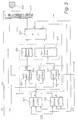
- Articulated bus 100 consists of a front end 101 and one with the front end 101 Trailers 102 connected via a joint 103.
- the front end 101 has two axes.
- the one at the front of the vehicle arranged, steerable front axle V is not driven.
- the rear axle of the front end 101, the central axle M is a driven axle.
- the wheels are braked on all axles, the ones on the wheels braking force generated at least axially by an anti-lock braking system is regulated.
- Electrical energy driven wheel hub motor 105 is arranged.
- the driving force on the wheel hub motors 105 becomes easier Way via the current supplied to the wheel hub motor 105 and / or controls the voltage applied to the wheel hub motor 105.
- the drive energy for the wheel hub motors 105 is, for example generated by an internal combustion engine 104 and in electrical Energy to be converted. But it can also do one Contact wire can be removed.
- the driver of the articulated bus 100 controls the desired driving force or braking force through the accelerator pedals 106,107.
- the driving force is over the accelerator pedal 106 is controlled.
- a path sensor 108 the position of the accelerator pedal 106 is detected and a corresponding one Signal supplied to the control unit 110.
- the position of the brake pedal 107 can be used in the same way with another displacement sensor 108 can be detected. Otherwise, the signal from a brake light switch be fed to the control. Also the unregulated generated only by operating the brake pedal 107 Brake pressure is a measure of the actuation of the brake pedal.
- the Control unit 110 is also the signal of the joint force sensor 111 transmitted that between the front car and the trailer transferred joint force detected. It is not enough that To determine the amount of joint force, it must at least also be determined whether the trailer is pulled from the front end or whether he pushes the front car.
- the wheel control devices 112 are used for each driven axle the driving force of the wheel hub motors 105 and the braking force controlled.
- the wheel hub motors 105 can also be used as generators.
- the generator power must be followed by the generator Load be regulated.
- the one generated by the generators Energy also in a store or possibly also be fed into the contact wire.
- An embodiment for wheel control device 112 is in the block diagram of FIG. 3 shown.
- the wheels of the front axle V are the wheel control units 113 assigned, which is different from the wheel control units distinguish that in them only the braking force over the brake pressure introduced into the wheel brakes is regulated.
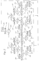
- step 2 shows the flow diagram of an inventive Control of driving force shown.
- the one from the joint force sensor measured joint force FG is in the control step fed.
- step 202 due to the under Taking into account the direction of force determined difference FG-FS between the joint force FG and the predetermined target joint force FS determines the differential force DF.
- the differential force is in in the simplest way half of the amount of the difference FG-FS.
- the driving force or the Braking force can be changed so that the control deviation between Target joint force FS and joint force FG is corrected.
- Step 203 is then taking into account the direction of force compared whether the joint force FG above or below the Target joint force FS is. If the joint force FG is less than the target joint force FS thus goes to step 204. Otherwise, the jump to step 215 takes place.
- step 204 it is then checked whether the articulated bus is driven or whether it is braked. This can be detected in a simple manner via the switching position of the brake light switch or via the position of the accelerator pedals 106, 107. If the vehicle is driven, the driving force FA M on the central axis M is increased by the differential force DF in step 205. In step 206 it is then checked whether this leads to a control intervention by the traction control system ASR (M) on the central axis M. As long as there is no regulation by the traction control system ASR (M), the driving force FA H on the rear axle is reduced by the differential force DF in step 209 and then a transition is made to step 226.
- M traction control system ASR
- the additional differential force DF ' is determined in step 207 on the basis of the maximum driving force FA M ' actually generated by the traction control system ASR (M).
- the value of the additional differential force DF ' is the amount of the difference between the actual driving force FA M ' and the driving force FA M.
- the drive force FA H is then determined on the rear axle H. It is reduced by the differential force DF and by the additional differential force DF '. Step 226 follows.
- step 226 it is checked whether the regulation of the driving force FA H by the traction control system ASR (H) has started on the rear axle. If this is the case, steps 227 and 228 are carried out. Otherwise, the system jumps back directly to step 201.
- step 227 the additional differential force DF 'is calculated, which results from the difference between the actual drive force FA H ' limited by the traction slip controller ASR (H) and the value for the drive force FA H on the rear axis H.
- step 228 the driving force on the central axis M is reduced by the amount of the additional differential force DF '. The process then returns to step 201 and a new control cycle follows.
- step 204 If it was determined in step 204 that the vehicle is braked, the braking force FB H is increased by the differential force DF in step 210. In step 211 it is checked whether this leads to a control intervention by the anti-lock braking system ABS (H) on the rear axle H. If this is the case, in step 212 the additional differential force DF 'is determined from the difference between the braking force FB H and the actual braking force FB H ' limited by the anti-lock braking system ABS (H). In step 213, the braking force FB VM on the front axle V and on the central axis M is then calculated by subtracting the amount of the differential force DF and the amount of the additional differential force DF 'from the braking force FB VM .
- ABS anti-lock braking system ABS
- step 229 follows the determination of the braking force FB VM .
- step 229 it is checked whether the control of the braking force FB VM by the anti-lock braking system ABS (VM) has started on the front axle V and on the central axis M. If this is the case, steps 230 and 231 are carried out. Otherwise, the system jumps back directly to step 201.
- step 230 the additional differential force DF 'is calculated, which results from the difference between the actual braking force FB VM ' limited by the anti-lock braking system ABS (VM) and the value for the braking force FB VM on the front axle V and the center axis M.
- step 231 the braking force FB H on the rear axle H is reduced by the amount of the additional differential force DF '. The system then jumps back to step 201 and a new control cycle follows.
- the control sequence is thus determined for the cases at which the target joint force is greater than the joint force.
- the What to do if it was determined in step 203 that the Target joint force is less than the joint force, is in Essentially 'symmetrical' to the previous one. the Process steps are only summarized briefly.
- step 215 it is checked whether the vehicle is driven. If this is not the case, steps 216 through close 22o and 232 to 234. Otherwise, steps 221 to follow 225 and 235 to 237.
- step 216 the braking force FB VM on the front end, that is on the front axle V and the center axis M, is increased by the amount of the differential force DF. If it is determined in step 217 that this leads to an intervention of the anti-lock braking system on the front axle V and central axis M, the additional differential force DF 'is determined in step 218. The braking force FB H on the rear axle is then reduced in accordance with step 218 by the differential force Df and the additional differential force DF '. If there is no regulation by the anti-lock braking system ABS (VM), the braking force FB H on the rear axle H is reduced by the differential force DF in accordance with step 22o.
- ABS anti-lock braking system ABS
- step 232 it is checked whether the braking force is controlled on the rear axle H. If this is the case, the additional differential force DF 'is determined in step 233 and the braking force FB VM is then reduced in step 234 by the additional differential force DF'. The process jumps back to step 201 and a new control cycle follows.
- step 221 the driving force FA H on the rear axle H is increased by the differential force. If it is determined in step 222 that traction control ASR (H) takes place on the rear axle H, the additional differential force DF 'is determined in accordance with step 223. The driving force FA M on the central axis H is reduced in step 224 by the differential force DF and the additional differential force DF '. If no intervention of the traction control system ASR (H) is found, then in step 225 the driving force FA M on the central axis M is reduced by the differential force DF. After determining the driving force FA M , it is checked in step 235 whether the traction control system ASR (M) is engaged on the central axis M. If this is the case, the additional differential force DF 'is determined in step 236 and the driving force FA H on the rear axle H is reduced by the amount of the differential force in step 237. The process jumps back to step 201.
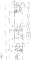
- FIG. 3 shows the block diagram of a wheel controller 105 Regulation of the driving force of a wheel hub motor and regulation the braking force on a wheel.
- the joint force measuring device 309 the joint force FG is measured. From the measured joint force FG and the target joint force FS becomes the control deviation determined.
- the wheel acceleration w ' is specified. This is possible because the wheel spin w 'in a direct relationship to that transmitted by the wheels Driving force FA stand.
- the drive case is one Drive wheel speed processing 302 and one for braking Brake speed processing 301 for the determination of the wheel acceleration w 'responsible.
- a target value for the wheel acceleration w 'is determined in the brake speed processing Taking into account the specifications of an anti-lock braking system, a target value for the wheel acceleration w 'is determined in the brake speed processing.
- a signal s B representing the position of the brake pedal is also fed to the brake controller 303 and the engine brake controller 304 and the control deviation of the joint force is fed.
- the brake controller then controls the service brake system 300 of the wheel assigned to it and controls the brake pressure PB on the wheel brakes.
- the wheel 308 changes its wheel speed w and the wheel rotational acceleration w 'on the basis of the brake pressure which may be generated.
- the behavior of the wheel 308 in turn influences the dynamic behavior of the articulated bus 310.
- the engine brake controller 304 regulates the generator power of the electric drive motor, the wheel hub motor 307, when the brake is applied to the brake. Both the current I
- Another setpoint value for the wheel spin acceleration w ' is carried out in the drive speed processing 302 taking into account a traction control system.
- the control deviation is determined from the determined target value and the actual value and fed to the drive controller 305.
- the drive controller is also fed a signal s G representing the position of the accelerator pedal and the control deviation of the joint force FG. From this, the drive controller determines the travel current I required by the wheel hub motor 307 or the required drive voltage U.
- the change in the operating state of the wheel hub motor 307 influences the wheel speed w and the wheel acceleration w 'and thereby the dynamics of the articulated bus.
- the invention is a control element that can be actuated by the driver provided that then allows the regulation of the driving force to refrain if the vehicle has a speed threshold, for example, has not exceeded 20 km / h. This is said to be in situations where all vehicle axles only a low driving force can be transmitted to the road can allow, without kink protection, the To start the vehicle. Usually is in this speed range the behavior of the vehicle for the driver controllable. Exceeding the speed threshold or press again or switch off the Ignition restarts the kink protection control.
Landscapes
- Engineering & Computer Science (AREA)
- Transportation (AREA)
- Mechanical Engineering (AREA)
- Power Engineering (AREA)
- Life Sciences & Earth Sciences (AREA)
- Sustainable Development (AREA)
- Sustainable Energy (AREA)
- Chemical & Material Sciences (AREA)
- Combustion & Propulsion (AREA)
- Physics & Mathematics (AREA)
- Electromagnetism (AREA)
- Regulating Braking Force (AREA)
Description
- Fig. 1
- eine schematische Darstellung eines Gelenkbusses und seinen Achsen,
- Fig. 2
- das Flußdiagramm einer erfindungsgemäßen Steuerung der Antriebskraft und der Bremskraft und
- Fig. 3
- das Blockschaltbild der Regelung der Antriebskraft und der Bremskraft für ein mit einem Radnabenmotor angetriebenen Rad.
Claims (16)
- Verfahren zur Begrenzung des Knickwinkels zwischen einem Vorderwagen und einem Nachläufer eines Gelenkomnibusses, bei dem zumindest eine Achse des Nachläufers und zumindest eine Achse des Vorderwagens angetrieben ist, bei dem die Antriebskraft und die Bremskraft durch Fahrpedale von einem Fahrer vorgegeben werden, und
die Differenz zwischen der erzeugten Antriebskraft (FAM) am Vorderwagen und der erzeugten Antriebskraft (FAH) am Nachläufer regelbar ist, bei welchem Verfahren
die im Gelenk (103) zwischen Vorderwagen (101) und Nachläufer (102) übertragene Gelenkkraft (FG) erfaßt wird undbeim Treiben die Differenz der Antriebskraft zwischen Vorderwagen (101) und Nachläufer (102) undbeim Bremsen die Differenz der Bremskraft zwischen Vorderwagen (101) und Nachläufer (102)
so geregelt wird, daß die übertragene Gelenkkraft (FG) einer vorgegebenen Sollgelenkkraft (FS) entspricht. - Verfahren nach Anspruch 1,
dadurch gekennzeichnet,
daß die Komponente der Gelenkkraft (FG) in Richtung des Vorderwagens (101) erfaßt wird. - Verfahren nach Anspruch 1 oder 2,
dadurch gekennzeichnet,
daß die Sollgelenkkraft (FS) in Richtung des Vorderwagens (101) gerichtet und so vorgegeben ist, daß der Nachläufer (102) vom Vorderwagen (101) gezogen wird. - Verfahren nach Anspruch 1,
dadurch gekennzeichnet,
daß in Abhängigkeit der Stellung der Fahrpedale (107,108) und aufgrund von aktuellen Raddrehzahlen (w) und von aktuellen Raddrehbeschleunigungen (w') Sollwerte für die Raddrehbeschleunigung der angetriebenen bzw. der gebremsten Räder ermittelt werden und daß die Antriebsleistung bzw. der Bremsdruck an den Rädern so geregelt wird, daß die Raddrehbeschleunigungen (w') den ermittelten Sollwerten der Raddrehbeschleunigung entsprechen. - Verfahren nach Anspruch 4,
dadurch gekennzeichnet,
daß den Rädern einer Achse derselbe Sollwert der Raddrehbeschleunigung zugeordnet ist. - Verfahren nach Anspruch 4,
dadurch gekennzeichnet,
daß bei der Ermittlung der Sollwerte für die Raddrehbeschleunigungen die Werte durch ein Antiblockiersystem und ein Antriebsschlupfregelsystem begrenzt sind. - Verfahren nach Anspruch 1,
dadurch gekennzeichnet,
daß die Differenz (FAM-FAH) beziehungsweise (FBVM-FBH) der Antriebskraft beziehungsweise der Bremskraft zwischen Vorderwagen (101) und Nachläufer (102) so verändert wird, daß die Summe der Antriebskraft bzw. die Summe der Bremskraft von Vorderwagen und Nachläufer konstant ist. - Verfahren nach Anspruch 7,
dadurch gekennzeichnet,
daß beim Bremsen die Summe der Bremskraft von Vorderwagen (101) und Nachläufer (102) dann nicht konstant ist, wenn an zumindest einer Achse (V,M,H) eine Regelung durch ein Antiblockiersystem erfolgt, wobei dann die Bremskraft durch die maximal erreichbare Bremskraft (FBH') am Nachläufer (102) begrenzt und die Bremskraft am Vorderwagen (101) so bestimmt ist, daß die übertragene Gelenkkraft (FG) der vorgegebenen Sollgelenkkraft (FS) entspricht oder diese zumindest nicht unterschreitet. - Verfahren nach Anspruch 7,
dadurch gekennzeichnet,
daß beim Treiben die Summe der Antriebskraft von Vorderwagen und Nachläufer dann nicht konstant ist, wenn an zumindest einer Achse eine Regelung durch eine Antriebsschlupfregelsystem erfolgt, wobei dann die Antriebskraft durch die maximal erreichbare Antriebskraft (FAM') am Vorderwagen (101) begrenzt und die Antriebskraft am Nachläufer (102) so bestimmt ist, daß die übertragene Gelenkkraft (FG) der vorgegebenen Sollgelenkkraft (FS) entspricht oder diese zumindest nicht unterschreitet. - Verfahren nach Anspruch 9,
dadurch gekennzeichnet,
daß unterhalb einer festgelegten Fahrgeschwindigkeitsschtwelle durch Betätigung eines Bedienelementes die Regelung der Gelenkkraft (FG) auf die vorgegebene Sollgelenkkraft (FS) solange außer Betrieb gesetzt wird, wie die Fahrgeschwindigkeitsschwelle nicht überschritten wird, und daß solange die Regelung der Gelenkkraft (FG) außer Betrieb gesetzt ist die Antriebskraft unabhängig für jede angetriebene Achse (V,M) aus der Stellung des Fahrpedals (106) bestimmt und durch ein Antriebsschlupfregelsystem geregelt wird. - Verfahren nach Anspruch 1,
dadurch gekennzeichnet,
daß die Antriebskraft an den Achsen durch Elektromotoren (105,307) erzeugt wird, wobei für die Spannung (U) und/oder der Strom (I) an den Elektromotoren (105,307) durch die Stellung des Fahrpedals (106) ein Wert vorgegeben wird, wobei ausgegehend von dem vorgegebenen Wert die Differenz zwischen Antriebskraft (FAM) am Vorderwagen (101) und Antriebskraft (FAH) am Nachläufer (102) durch Regelung der Spannung (U) und/oder des Stromes (I) der Elektromotoren (105,307) zumindest des Vorderwagens (101) oder zumindest des Nachläufers (102) erzeugt wird. - Verfahren nach Anspruch 11,
dadurch gekennzeichnet,
daß die Elektromotoren (105,307) Radnabenmotoren sind. - Verfahren nach Anspruch 11,
dadurch gekennzeichnet,
daß bei Bremspedalbetätigung die Elektromotoren (105,307) als Generatoren verwendet werden. - Verfahren nach Anspruch 13,
dadurch gekennzeichnet,
daß die in den als Generatoren arbeitenden Elektromotoren (105,307) erzeugte Energie in ein Fahrstromnetz eingespeist oder in einem Energiespeicher gespeichert wird. - Verfahren nach Anspruch 14,
dadurch gekennzeichnet,
daß die Generatorleistung in Abhängigkeit der durch sie erzeugten Bremskraft (FBH,FBM) geregelt ist. - Verfahren nach Anspruch 1,
dadurch gekennzeichnet,
daß zur Steuerung der Bremskraft (FBH,FBVM) die Stellglieder eines Antiblockiersystems genutzt werden.
Applications Claiming Priority (2)
| Application Number | Priority Date | Filing Date | Title |
|---|---|---|---|
| DE4431698 | 1994-09-06 | ||
| DE4431698A DE4431698C1 (de) | 1994-09-06 | 1994-09-06 | Verfahren zur Begrenzung des Knickwinkels zwischen dem Vorderwagen und dem Nachläufer eines Gelenkomnibusses |
Publications (3)
| Publication Number | Publication Date |
|---|---|
| EP0700822A2 EP0700822A2 (de) | 1996-03-13 |
| EP0700822A3 EP0700822A3 (de) | 1997-04-23 |
| EP0700822B1 true EP0700822B1 (de) | 1998-11-11 |
Family
ID=6527533
Family Applications (1)
| Application Number | Title | Priority Date | Filing Date |
|---|---|---|---|
| EP95112828A Expired - Lifetime EP0700822B1 (de) | 1994-09-06 | 1995-08-16 | Verfahren zur Begrenzung des Knickwinkels zwischen dem Vorderwagen und dem Nachläufer eines Gelenkomnibusses |
Country Status (2)
| Country | Link |
|---|---|
| EP (1) | EP0700822B1 (de) |
| DE (1) | DE4431698C1 (de) |
Cited By (6)
| Publication number | Priority date | Publication date | Assignee | Title |
|---|---|---|---|---|
| US10670479B2 (en) | 2018-02-27 | 2020-06-02 | Methode Electronics, Inc. | Towing systems and methods using magnetic field sensing |
| US10696109B2 (en) | 2017-03-22 | 2020-06-30 | Methode Electronics Malta Ltd. | Magnetolastic based sensor assembly |
| US11084342B2 (en) | 2018-02-27 | 2021-08-10 | Methode Electronics, Inc. | Towing systems and methods using magnetic field sensing |
| US11135882B2 (en) | 2018-02-27 | 2021-10-05 | Methode Electronics, Inc. | Towing systems and methods using magnetic field sensing |
| US11221262B2 (en) | 2018-02-27 | 2022-01-11 | Methode Electronics, Inc. | Towing systems and methods using magnetic field sensing |
| US11491832B2 (en) | 2018-02-27 | 2022-11-08 | Methode Electronics, Inc. | Towing systems and methods using magnetic field sensing |
Families Citing this family (8)
| Publication number | Priority date | Publication date | Assignee | Title |
|---|---|---|---|---|
| DE19548716C2 (de) * | 1995-12-23 | 1998-04-09 | Daimler Benz Ag | Nicht spurgebundenes Gelenkfahrzeug |
| DE19859953A1 (de) * | 1998-12-28 | 2000-06-29 | Bosch Gmbh Robert | Vorrichtung und Verfahren zur Stabilisierung eines aus einem Zugfahrzeug und einem Anhänger bzw. Auflieger bestehenden Fahrzeuggespannes |
| DE10139101A1 (de) * | 2001-08-09 | 2003-03-13 | Knorr Bremse Systeme | Verfahren und Vorrichtung zur Spurstabilisierung von Gelenkfahrzeugen, insbesondere Gelenkbussen |
| DE102004029461A1 (de) * | 2004-06-18 | 2006-01-12 | Daimlerchrysler Ag | Zweigliedriger Gelenkomnibus |
| DE102014211268B4 (de) | 2014-06-12 | 2024-11-28 | Bayerische Motoren Werke Aktiengesellschaft | Verfahren und Gespann-Stabilisationsvorrichtung zum Stabilisieren des Schlingerverhaltens eines Gespanns und Gespann |
| DE102014010590A1 (de) | 2014-07-16 | 2015-01-15 | Daimler Ag | Verfahren zur Stabilisierung eines Fahrzeugs |
| DE102021005667A1 (de) | 2021-11-16 | 2022-01-27 | Daimler Ag | Gierschwingungs-Reduktion für Fahrzeug-Gespanne |
| DE102021005664A1 (de) | 2021-11-16 | 2022-01-13 | Daimler Ag | Schwenkschutzsystem für ein Fahrzeuggespann |
Family Cites Families (10)
| Publication number | Priority date | Publication date | Assignee | Title |
|---|---|---|---|---|
| US4231442A (en) * | 1974-06-15 | 1980-11-04 | Mogens Birkeholm | Apparatus for braking a train of vehicles |
| US4060284A (en) * | 1974-07-22 | 1977-11-29 | Daimler-Benz Aktiengesellschaft | Installation for the control of the brake force at wheels of motor vehicles |
| US4119166A (en) * | 1977-07-01 | 1978-10-10 | General Motors Corporation | Dual-vehicle operating system |
| IT1093561B (it) * | 1978-04-04 | 1985-07-19 | Mauri & C Snc | Autoveicoli articolato per trasproto pubblico |
| FR2465628A2 (fr) * | 1979-02-21 | 1981-03-27 | Heuliez Sa Louis | Vehicule sur roues du type articule pousseur |
| FR2450171A1 (fr) * | 1979-03-01 | 1980-09-26 | Renault Vehicules Ind | Dispositif de transmission pour vehicules de transport en commun a plusieurs elements articules |
| FR2611611B1 (fr) * | 1987-02-26 | 1991-04-05 | Chapuis Pere Fils | Dispositif de propulsion d'un vehicule en remorque relie a un premier vehicule auto-propulseur |
| US4853553A (en) * | 1987-10-30 | 1989-08-01 | Hosie Alan P | Dual mode diesel electric power system for vehicles |
| DE4035805C1 (de) * | 1990-11-10 | 1992-03-05 | Mercedes-Benz Aktiengesellschaft, 7000 Stuttgart, De | |
| DE4243245A1 (de) * | 1992-12-19 | 1994-06-23 | Wabco Westinghouse Fahrzeug | Verfahren zur Abbremsung eines Fahrzeugzuges |
-
1994
- 1994-09-06 DE DE4431698A patent/DE4431698C1/de not_active Expired - Fee Related
-
1995
- 1995-08-16 EP EP95112828A patent/EP0700822B1/de not_active Expired - Lifetime
Cited By (7)
| Publication number | Priority date | Publication date | Assignee | Title |
|---|---|---|---|---|
| US10696109B2 (en) | 2017-03-22 | 2020-06-30 | Methode Electronics Malta Ltd. | Magnetolastic based sensor assembly |
| US10940726B2 (en) | 2017-03-22 | 2021-03-09 | Methode Electronics Malta Ltd. | Magnetoelastic based sensor assembly |
| US10670479B2 (en) | 2018-02-27 | 2020-06-02 | Methode Electronics, Inc. | Towing systems and methods using magnetic field sensing |
| US11084342B2 (en) | 2018-02-27 | 2021-08-10 | Methode Electronics, Inc. | Towing systems and methods using magnetic field sensing |
| US11135882B2 (en) | 2018-02-27 | 2021-10-05 | Methode Electronics, Inc. | Towing systems and methods using magnetic field sensing |
| US11221262B2 (en) | 2018-02-27 | 2022-01-11 | Methode Electronics, Inc. | Towing systems and methods using magnetic field sensing |
| US11491832B2 (en) | 2018-02-27 | 2022-11-08 | Methode Electronics, Inc. | Towing systems and methods using magnetic field sensing |
Also Published As
| Publication number | Publication date |
|---|---|
| EP0700822A2 (de) | 1996-03-13 |
| DE4431698C1 (de) | 1995-09-21 |
| EP0700822A3 (de) | 1997-04-23 |
Similar Documents
| Publication | Publication Date | Title |
|---|---|---|
| EP4003771B1 (de) | Verfahren zum unterstützen eines zugfahrzeugs bei traktionsverlust | |
| EP1062114B1 (de) | Verfahren und vorrichtung zum statischen oder dynamischen ermitteln von sollwerten für bremskräfte oder bremsmomente | |
| EP1047585B1 (de) | Verfahren und vorrichtung zur stabilisierung eines fahrzeuges im sinne einer umkippvermeidung | |
| EP0954461B1 (de) | Verfahren und vorrichtung zur erkennung einer kipptendenz eines fahrzeuges | |
| EP2144794B1 (de) | Verfahren zum betrieb einer fahrzeugbremsanlage sowie fahrzeugbremsanlage | |
| EP2760714B1 (de) | Schlupfgeregeltes bremssystem für elektrisch angetriebene kraftfahrzeuge | |
| DE4133912C2 (de) | ||
| EP1056630B1 (de) | Vorrichtung und verfahren zur stabilisierung eines fahrzeuges | |
| DE4438252C2 (de) | Verfahren und Vorrichtung zur elektronischen Steuerung der Bremsanlage eines Fahrzeugs | |
| EP2040962B1 (de) | Verfahren zum kompensieren der bremsverzögerung bei einer fahrzeugregelung | |
| EP0700822B1 (de) | Verfahren zur Begrenzung des Knickwinkels zwischen dem Vorderwagen und dem Nachläufer eines Gelenkomnibusses | |
| EP0996558A1 (de) | Verfahren und vorrichtung zur stabilisierung eines fahrzeuges | |
| DE102020202477A1 (de) | Sicherheitssystem für einen elektrisch antreibbaren Kraftwagen, Verfahren zum Betreiben eines solchen Sicherheitssystems sowie Kraftwagen | |
| WO2008037347A1 (de) | Bremssystem und verfahren zum bremsen eines fahrzeugs mit einem hybridantrieb | |
| EP1016572A2 (de) | Vorrichtung und Verfahren zur Stabilisierung eines aus einem Zugfahrzeug und einem Anhänger bzw. Auflieger bestehenden Fahrzeuggespannes | |
| WO2011076534A1 (de) | Verfahren und vorrichtung zur verteilung eines antriebsmomentes auf die räder einer elektrisch angetriebenen achse eines kraftfahrzeuges | |
| DE19540067A1 (de) | Verfahren zur Regelung des getrennten Antriebs zweier Fahrzeugräder | |
| DE112005001001B4 (de) | Verfahren für die Steuerung eines Bremssystems eines Kraftfahrzeuges | |
| EP1045783B1 (de) | Vorrichtung und verfahren zum begrenzen einer rückrollgeschwindigkeit eines kraftfahrzeuges | |
| DE102006033257B4 (de) | Lastverlagerungsadaptive Antriebs-Schlupf-Regelung | |
| DE102021204001B4 (de) | Verfahren zur Antriebsregelung eines Anhängers und Antriebsvorrichtung | |
| DE19734112A1 (de) | Verfahren und Vorrichtung zur Antriebsschlupfregelung bei Kraftfahrzeugen | |
| EP0844954B1 (de) | Verfahren und vorrichtung zur steuerung der bremsanlage eines fahrzeugs | |
| DE102022116596A1 (de) | Anhängersteuergerät zum Ansteuern eines elektrischen Antriebs eines Anhängerfahrzeugs sowie Verfahren zum Ansteuern des elektrischen Antriebs mit dem Anhängersteuergerät | |
| DE102019204205A1 (de) | Verfahren zum Betreiben eines Antriebssystems eines Elektrofahrzeugs und Antriebssystem für ein Elektrofahrzeug |
Legal Events
| Date | Code | Title | Description |
|---|---|---|---|
| PUAI | Public reference made under article 153(3) epc to a published international application that has entered the european phase |
Free format text: ORIGINAL CODE: 0009012 |
|
| AK | Designated contracting states |
Kind code of ref document: A2 Designated state(s): BE FR IT SE |
|
| PUAL | Search report despatched |
Free format text: ORIGINAL CODE: 0009013 |
|
| AK | Designated contracting states |
Kind code of ref document: A3 Designated state(s): BE FR IT SE |
|
| 17P | Request for examination filed |
Effective date: 19970318 |
|
| 17Q | First examination report despatched |
Effective date: 19970602 |
|
| RAP1 | Party data changed (applicant data changed or rights of an application transferred) |
Owner name: DAIMLER-BENZ AKTIENGESELLSCHAFT |
|
| GRAG | Despatch of communication of intention to grant |
Free format text: ORIGINAL CODE: EPIDOS AGRA |
|
| GRAG | Despatch of communication of intention to grant |
Free format text: ORIGINAL CODE: EPIDOS AGRA |
|
| GRAH | Despatch of communication of intention to grant a patent |
Free format text: ORIGINAL CODE: EPIDOS IGRA |
|
| GRAH | Despatch of communication of intention to grant a patent |
Free format text: ORIGINAL CODE: EPIDOS IGRA |
|
| GRAA | (expected) grant |
Free format text: ORIGINAL CODE: 0009210 |
|
| AK | Designated contracting states |
Kind code of ref document: B1 Designated state(s): BE FR IT SE |
|
| ET | Fr: translation filed | ||
| RAP2 | Party data changed (patent owner data changed or rights of a patent transferred) |
Owner name: DAIMLERCHRYSLER AG |
|
| PLBE | No opposition filed within time limit |
Free format text: ORIGINAL CODE: 0009261 |
|
| STAA | Information on the status of an ep patent application or granted ep patent |
Free format text: STATUS: NO OPPOSITION FILED WITHIN TIME LIMIT |
|
| 26N | No opposition filed | ||
| PGFP | Annual fee paid to national office [announced via postgrant information from national office to epo] |
Ref country code: SE Payment date: 20020725 Year of fee payment: 8 |
|
| PGFP | Annual fee paid to national office [announced via postgrant information from national office to epo] |
Ref country code: BE Payment date: 20020726 Year of fee payment: 8 |
|
| PGFP | Annual fee paid to national office [announced via postgrant information from national office to epo] |
Ref country code: FR Payment date: 20020812 Year of fee payment: 8 |
|
| PG25 | Lapsed in a contracting state [announced via postgrant information from national office to epo] |
Ref country code: SE Free format text: LAPSE BECAUSE OF NON-PAYMENT OF DUE FEES Effective date: 20030817 |
|
| PG25 | Lapsed in a contracting state [announced via postgrant information from national office to epo] |
Ref country code: BE Free format text: LAPSE BECAUSE OF NON-PAYMENT OF DUE FEES Effective date: 20030831 |
|
| BERE | Be: lapsed |
Owner name: *DAIMLERCHRYSLER A.G. Effective date: 20030831 |
|
| EUG | Se: european patent has lapsed | ||
| PG25 | Lapsed in a contracting state [announced via postgrant information from national office to epo] |
Ref country code: FR Free format text: LAPSE BECAUSE OF NON-PAYMENT OF DUE FEES Effective date: 20040430 |
|
| REG | Reference to a national code |
Ref country code: FR Ref legal event code: ST |
|
| PG25 | Lapsed in a contracting state [announced via postgrant information from national office to epo] |
Ref country code: IT Free format text: LAPSE BECAUSE OF NON-PAYMENT OF DUE FEES;WARNING: LAPSES OF ITALIAN PATENTS WITH EFFECTIVE DATE BEFORE 2007 MAY HAVE OCCURRED AT ANY TIME BEFORE 2007. THE CORRECT EFFECTIVE DATE MAY BE DIFFERENT FROM THE ONE RECORDED. Effective date: 20050816 |