EP0698949A2 - Leiterplattenrandverbinder mit Keilverriegelungselement und Auswurfmechanismus - Google Patents
Leiterplattenrandverbinder mit Keilverriegelungselement und Auswurfmechanismus Download PDFInfo
- Publication number
- EP0698949A2 EP0698949A2 EP95304702A EP95304702A EP0698949A2 EP 0698949 A2 EP0698949 A2 EP 0698949A2 EP 95304702 A EP95304702 A EP 95304702A EP 95304702 A EP95304702 A EP 95304702A EP 0698949 A2 EP0698949 A2 EP 0698949A2
- Authority
- EP
- European Patent Office
- Prior art keywords
- circuit card
- card
- projection
- slot
- ledge
- Prior art date
- Legal status (The legal status is an assumption and is not a legal conclusion. Google has not performed a legal analysis and makes no representation as to the accuracy of the status listed.)
- Ceased
Links
Images

Classifications
-
- H—ELECTRICITY
- H01—ELECTRIC ELEMENTS
- H01R—ELECTRICALLY-CONDUCTIVE CONNECTIONS; STRUCTURAL ASSOCIATIONS OF A PLURALITY OF MUTUALLY-INSULATED ELECTRICAL CONNECTING ELEMENTS; COUPLING DEVICES; CURRENT COLLECTORS
- H01R12/00—Structural associations of a plurality of mutually-insulated electrical connecting elements, specially adapted for printed circuits, e.g. printed circuit boards [PCB], flat or ribbon cables, or like generally planar structures, e.g. terminal strips, terminal blocks; Coupling devices specially adapted for printed circuits, flat or ribbon cables, or like generally planar structures; Terminals specially adapted for contact with, or insertion into, printed circuits, flat or ribbon cables, or like generally planar structures
- H01R12/70—Coupling devices
- H01R12/7005—Guiding, mounting, polarizing or locking means; Extractors
Definitions
- the invention relates to a card edge electrical connector having a mechanism for releasably locking a circuit card in the connector and for extracting the circuit card therefrom.
- Sockets for electrically interconnecting a circuit board daughtercard to a circuit board mothercard are well-known.
- Such sockets include an insulative housing having an elongated slot for receiving an edge portion of the daughtercard. Contacts in the housing extend into the slot for engagement with contact pads on the daughtercard, and the contacts have leads which extend to an extericr of the housing for engagement with mating circuit traces on the mothercard.
- the sockets may be either of the cam-in or direct insertion type.
- the cam-in type allows the daughtercard to be inserted into the slot at a first orientation with a zero insertion force. The card is then pivoted to a second orientation against spring forces exhibited by the contacts, and the card is retained in the second orientation by a latching device.
- the daughtercard In the direct insertion type of socket, the daughtercard is inserted into the slot with a single straight line motion. There may be considerable resistance to insertion of the card due to friction forces of the contacts wiping against the card as the card is inserted into the slot. The contacts exert a normal force on the card in the slot, and these normal forces generate a frictional resistance to removal of the card from the socket. The frictional resistance contributes greatly to retaining the card in the socket and may be sufficient to retain the card in some cases.
- the cards are manufactured with a tolerance on their thickness, and a card that is near the minimum thickness will experience less frictional resistance than a card that is near the maximum thickness. Since vibration, shock and thermal stresses can cause a card to back out of its socket, additional retention mechanisms have been employed to ensure retention of the card therein.
- U.S. Patent No. 4,973,270 discloses a direct insertion type socket having card guides at each end which define grooves aligned with the card receiving slots.
- Opposed walls of each groove include a pair of opposed ridges which are spaced apart by a distance which is less than a minimum thickness of the card to be received therein.
- One of the walls is relatively thin so as to be somewhat flexible. Insertion of a daughtercard between the walls deflects the flexible wall and expands the groove, thereby frictionally retaining the card.
- the flexible wall also accommodates cards having different thicknesses.
- U.S. Patent No. 5,074,800 discloses a pivotable lever having a locking mechanism and an extraction mechanism for a card edge connector.
- the extraction mechanism comprises an extractor foot that underlies the circuit card to enable ejection thereof.
- the locking mechanism includes lock arms having projections which engage in an associated locking hole in the circuit card from opposite sides thereof to lock the card in the socket.
- circuit cards, or module cards are produced in at least two standard types each having a locking hole at a respective specified dimension from an edge of the card.
- the locking projections must be disposed to engage in the locking hole of one of the standard card types, and the locking projections for different card types are not interchangeable.
- due to dimensional tolerances on the lever and the card there is a possibility that a load may be placed on the extractor during locking of the card in the socket. There is a need for a locking and extraction mechanism which will accommodate different standard card types.
- a socket has a card locking mechanism which will accommodate different standard circuit card types.
- a socket for electrically connecting a circuit card to a substrate wherein the socket comprises a housing which defines an elongated slot dimensioned for receiving an edge portion of the circuit card.
- a plurality of contacts extent into the slot for electrically engaging respective contact pads on the circuit card, and leads of the contacts extend to an exterior of the housing for electrically engaging respective circuit traces on the substrate.
- a card guide at one end of the slot includes first and second spaced apart walls arrayed on respective opposite sides of an elongation axis of the slot. A space between the walls is greater than a thickness of the circuit card.
- the first wall is substantially rigid and has a projection extending into the space in a fixed position and arranged to reside above a ledge of the circuit card when the circuit card is disposed in the slot.
- a gap between a tip of the projection and the second wall has a dimension at least as great as the thickness of the circuit card, whereby the circuit card is insertable into the socket with a portion of the circuit card passing through the gap until the ledge is relatively below the projection, the ledge is displaceable to a position beneath the projection upon relative lateral movement of the circuit card, and whereby a clearance exists between the circuit card and the second wall when the circuit card is disposed in the slot and the projection resides above the ledge.
- a shim member which is insertable in the clearance is dimensioned to restrict lateral movement of the circuit card sufficiently to prevent displacement of the ledge beyond the tip of the projection, whereby the circuit card is locked in the socket.
- Fig. 1 is an isometric view of a socket according to the invention.
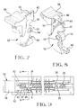
- Fig. 2 is an isometric view of a card guide at one end of the socket, the view being taken at an orientation which is rotated 90° from the orientation of Fig. 1.
- Fig. 3 is a top view of the socket having a lock lever in an unlocked position.
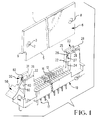
- Fig. 4 is a cross-sectional view taken along line 4-4 of Fig. 3, showing the lock lever exploded away.
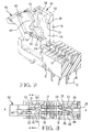
- Fig. 5 is a cross-sectional view showing partial insertion of a circuit card in the socket.
- Fig. 6 is a cross-sectional view showing the circuit card locked in the socket.
- Fig. 7 is an isometric view of the lock lever.
- Fig. 8 is an isometric view of the lock lever rotated 90° from the view of Fig. 7.
- Fig. 9 is a top view of the socket having a circuit card therein and the lock lever in a locked position.
- a socket comprising a housing 10 made from an insulative material, preferably a liquid crystal polymer.
- the housing 10 has an elongated slot 12 which extends between opposite ends of the housing 10.
- the slot 12 is dimensioned to receive a circuit panel daughtercard 6 having contact pads (not shown) along a margin area adjacent edge 5 of the card.
- Contacts 16 which are disposed in grooves in the housing 10 extend into the slot 12 for electrically engaging the contact pads on the circuit card 6 when it is received in the slot 12.
- the contacts 16 have respective leads 17 which extend to an exterior of the housing 10 for electrically engaging respective circuit traces on a mothercard substrate (not shown) such as by conventional surface mount or through-hole solder techniques.
- the housing 10 has card guides or supports 20, 30 at respective opposite ends thereof for stabilizing the card in the socket.
- the card guide 20 comprises a pair of upstanding walls 22 having a space or groove 24 therebetween.
- the card guide 30 comprises a first wall 31 and a spaced apart second wall 32, a space between the walls 31, 32 forming a groove 34.
- the walls of each card guide are arrayed on respective opposite sides of an elongation axis A-A of the slot 12, and the grooves 24 and 34 are aligned with and open to the slot 12 at respective opposite ends thereof.
- the slot 12 and the grooves 24, 34 are slightly wider than the thickness of the circuit card 6 to permit insertion of the circuit card therein.
- the card guide 20 has opposed projections 26 extending from upper ends of the walls 22.
- a dimension between the projections 26 is selected to be marginally narrower than the thickness of the circuit card 6.
- the walls 22 are somewhat flexible due to their cantilever attachment to the housing 10 to allow bending of the walls 22 and increased separation of the projections 26 so that the card 6 may be inserted into the socket.
- the projections 26 are arranged to align with hole 8 in the card 6 when the card is fully inserted in the socket.
- the card guide 20 further comprises an end beam 28 having a surface 29 which serves to axially locate the card 6 in the slot 12.
- the card guide 30 has a projection 36 extending from the first wall 31 partially across the groove 34 toward the second wall 32.
- the projection 36 is dimensioned such that a gap 38 between a tip of the projection 36 and the second wall 32 is at least as great as the thickness of the card 6, whereby the card 6 may still be inserted easily into the groove 34.
- surface 39 of the first wall 31 is coplanar with side 13 of the slot 12 and, for a circuit card having a nominal thickness of .050 inch, the gap 38 is on the order of .040 inch.
- the projection 36 is arranged to reside above a ledge 2 of the card 6 when the card is disposed in the slot 12.
- the ledge 2 of the card 6 is defined by a wall surface of hole 3 in the card, although the ledge could simply be defined by a top edge 7 of the card 6.
- the wall 31 is preferably rigid so that it will not bend and thereby withdraw the projection 36 from above the ledge 2. Rigidity is achieved by a relatively greater thickness of the first wall 31 as compared to the second wall 32.
- the card 6 is insertable into the socket with a substantially straight-in motion.
- the leading edge 5 of the card engages beveled top surfaces 25 of the projections 26 and cams the projections outwardly of the plane of the card so that the card can slip between the projections 26 until the projections 26 become aligned with and enter the hole 8.
- the beveled top surfaces 25 also serve to pinch the card 6 from opposite sides thereof once the card is disposed in the slot to help stabilize the card in the socket.
- Bottom surfaces 27 of the projections 26 have a slight bevel of approximately 15° upwardly as the bottom surfaces extend toward their respective projection tips. The beveled bottom surfaces contribute to camming of the projections outwardly of the plane of the card as the card is urged upwardly during removal of the card from the socket.
- the card is offset slightly from vertical, as shown in Fig. 5.
- the card is inserted sufficiently in the slot 12 for proper engagement of the socket contacts 16 with their respective contact pads on the card.
- the card is then pivotably moveable laterally to displace the ledge 2 to a position beneath the projection 36, as shown in Fig. 6.
- a clearance 48 exists between the card 6 and the second wall 32, as shown in Fig. 9, the clearance 48 being less than a width of the gap 38 due to some thickness of the card extending beyond the tip of the projection 36.
- a shim member 40 is movable between a lock position wherein the shim member 40 is disposed in the clearance 48, and an unlock position wherein the shim member is withdrawn from the clearance.
- the shim member 40 is an integral part of a lock lever 50 which is pivotally connected to the housing 10.
- the lock lever 50 has a boss with an arcuate shaped front surface 52. Cylindrical recesses 54 formed in side walls of the boss receive journals 56 which extend into the groove 34 of the card guide 30 from the walls 31 and 32, as shown in Fig. 4.
- the lock lever 50 is pivotable on the journals 56 on an axis transverse to the elongation axis A-A of the slot.
- the lock lever 50 has a finger grip 58 to aid pivoting actuation thereof.
- a notch surface 9 of the card 6 rides on the arcuate shaped surface 52 to further locate and stabilize the card in the socket.
- Lugs 60 on the lock lever 50 cooperate with detents 62 in the first and second walls 31, 32 to provide a means for releasably holding the lock lever in the lock position.
- the shim member 40 is a plate-like extension having a thickness which is on the order of several thousandths of an inch greater than the width of the clearance 48.
- a leading edge 42 of the shim member is beveled to assist entry of the shim member into the clearance 48, and the shim member resides in the clearance with an interference fit between the second wall 32 and the card 6.
- the second wall 32 is not as stiff as the rigid first wall 31, and the second wall 32 may bend upon insertion of the shim member 40 in the clearance, which bending reduces resistance to insertion of the shim member and serves to accommodate cards having a thickness which is near a maximum of the card thickness tolerance.
- the lock lever 50 also includes extractor foot 64 which underlies the leading edge 5 of the card when the card is disposed in the slot.
- the extractor foot 64 kicks an end of the card out of the slot when the lock lever is pivoted to the unlock position.
- the bottom surface 37 of the projection 36 has a slight bevel of approximately 15° upwardly as the bottom surface extends toward the projection tip, the bevel serving to cam the card outwardly of the ledge 36 as the extractor foot urges the card upwardly.
- insertion of the card into the socket causes pivoting of the lock lever and movement of shim member 40 to the locked position as the leading edge 5 urges the extractor foot 64 downwardly.
- the lock lever 50 be in the unlock position shown in Fig. 2 before inserting the card into the socket.
- operating personnel may not be cognizant of the preferred method of operation of the locking mechanism or may not be meticulous in performing preferred operations, and it is anticipated that personnel will attempt to insert the card into the socket with the lock lever in the lock position. It is an advantage of the invention that the card may be inserted into the socket even when the lock lever carrying the shim member 40 is in the lock position shown in Fig. 6, without detriment to the lock and extractor mechanism.
- Beveled upper edge 44 of the shim member 40 acts as a guide and camming surface to guide the card into the slot and cam the shim member 40 away from the projection 36, in conjunction with bending of the wall 32, until the ledge 2 passes beneath the projection 36, thereby allowing the card to slide between the projection 36 and the shim member 40 even when the lock lever is in the lock position.
- a socket according to the invention may have a lock and extractor mechanism at one or both ends of the slot 12. Further, multiple lock and extractor mechanisms may be incorporated in a multi-card electrical connector such as a dual row, dual in-line memory module (DIMM) socket which has a pair of card-receiving slots in parallel, side-by-side arrangement.
- DIMM dual in-line memory module
- the dual row DIMM socket may have a single or a pair of lock and extractor mechanisms dedicated to each row of the socket.
- a socket according to the invention has the advantages that a circuit card is locked in the socket by a shim member that prevents lateral movement of the circuit card so that a ledge of the circuit card is maintained beneath a projection of the socket.
- the shim member is disposed on a lock lever which may also have an extractor foot. The extractor foot is not placed under any load when the card is locked in the socket. Further, the lock lever having the shim member is readily adapted for use with different standard types of module cards.
Landscapes
- Details Of Connecting Devices For Male And Female Coupling (AREA)
- Coupling Device And Connection With Printed Circuit (AREA)
Applications Claiming Priority (2)
| Application Number | Priority Date | Filing Date | Title |
|---|---|---|---|
| US08/294,695 US5445531A (en) | 1994-08-23 | 1994-08-23 | Card edge connector with shim lock and extractor mechanism |
| US294695 | 2002-11-15 |
Publications (2)
| Publication Number | Publication Date |
|---|---|
| EP0698949A2 true EP0698949A2 (de) | 1996-02-28 |
| EP0698949A3 EP0698949A3 (de) | 1997-08-20 |
Family
ID=23134531
Family Applications (1)
| Application Number | Title | Priority Date | Filing Date |
|---|---|---|---|
| EP95304702A Ceased EP0698949A3 (de) | 1994-08-23 | 1995-07-05 | Leiterplattenrandverbinder mit Keilverriegelungselement und Auswurfmechanismus |
Country Status (3)
| Country | Link |
|---|---|
| US (1) | US5445531A (de) |
| EP (1) | EP0698949A3 (de) |
| JP (1) | JPH0869836A (de) |
Cited By (1)
| Publication number | Priority date | Publication date | Assignee | Title |
|---|---|---|---|---|
| EP0799508A1 (de) * | 1994-12-21 | 1997-10-08 | Berg Technology, Inc. | Leiterplattenfassung |
Families Citing this family (37)
| Publication number | Priority date | Publication date | Assignee | Title |
|---|---|---|---|---|
| US6276950B1 (en) * | 1994-12-21 | 2001-08-21 | Berg Technology, Inc. | Socket for printed circuit board |
| JPH10511499A (ja) * | 1994-12-27 | 1998-11-04 | バーグ・テクノロジー・インコーポレーテッド | カードエッジコネクター装置 |
| US5542854A (en) * | 1995-01-17 | 1996-08-06 | Molex Incorporated | Edge card connector with alignment means |
| US5746613A (en) * | 1995-04-12 | 1998-05-05 | Hon Hai Precision Ind. Co., Ltd. | Card edge connector with ejector |
| TW395069B (en) * | 1995-08-23 | 2000-06-21 | Connector Systems Tech Nv | Connector |
| US5558528A (en) * | 1995-11-13 | 1996-09-24 | Hon Hai Precision Ind. Co., Ltd. | Connector with ejector |
| US5662485A (en) * | 1996-01-19 | 1997-09-02 | Framatome Connectors Usa Inc. | Printed circuit board connector with locking ejector |
| US5690499A (en) * | 1996-09-23 | 1997-11-25 | The Whitaker Corporation | Card edge socket having extractor with closed position lock |
| TW361716U (en) * | 1996-10-15 | 1999-06-11 | Hon Hai Prec Ind Co Ltd | Power connector with concealed buckles |
| US5676561A (en) * | 1996-11-05 | 1997-10-14 | Nextronics Engineering Co., Ltd. | Edge card connector having guide units with sufficient resiliency |
| TW435850U (en) * | 1997-03-04 | 2001-05-16 | Hon Hai Prec Ind Co Ltd | Card edge connector having card-ejecting device |
| US6038131A (en) * | 1998-01-13 | 2000-03-14 | Sci Systems, Inc. | Electrical component mounting assembly including special guide structure for receiving a component package regardless of orientation of the package relative to the guides |
| DE19832598C2 (de) * | 1998-07-09 | 2002-02-14 | Poly An Gmbh | Oberflächenmodifizierung von Mikrotiterplatten mit pH- und/oder redoxsensitiven und/oder molekular geprägten Polymeren sowie die Verwendung solcher modifizierter Mikrotiterplatten in Assays bzw. Test- und Screeningssystemen |
| DE19947031C1 (de) * | 1999-09-30 | 2001-03-08 | Tyco Electronics Logistics Ag | Leiterplattensteckverbinder |
| US6464537B1 (en) | 1999-12-29 | 2002-10-15 | Berg Technology, Inc. | High speed card edge connectors |
| TW572442U (en) * | 2003-06-03 | 2004-01-11 | Hon Hai Prec Ind Co Ltd | Card edge connector |
| TW200536210A (en) * | 2004-04-19 | 2005-11-01 | Top Yang Technology Entpr Co | Card board structure for electric connector |
| US6948957B1 (en) | 2004-05-06 | 2005-09-27 | Tyco Electronics Corporation | Socket for retaining in-line modules |
| SG123614A1 (en) * | 2004-12-09 | 2006-07-26 | Molex Inc | Electrical connector socket with latch mechanism |
| CN2874841Y (zh) * | 2005-10-21 | 2007-02-28 | 富士康(昆山)电脑接插件有限公司 | 电连接器 |
| US7371097B1 (en) | 2007-02-07 | 2008-05-13 | Tyco Electronics Corporation | Socket connector with latch locking member |
| CN201041841Y (zh) * | 2007-03-09 | 2008-03-26 | 富士康(昆山)电脑接插件有限公司 | 卡缘连接器 |
| JP4958645B2 (ja) | 2007-06-06 | 2012-06-20 | 矢崎総業株式会社 | 基板接続コネクタ |
| CN101420082B (zh) * | 2007-10-22 | 2011-03-23 | 华硕电脑股份有限公司 | 电子装置及其连接器及其电子卡片取放方法 |
| US8064210B2 (en) * | 2008-10-16 | 2011-11-22 | Airtronics Metal Products, Inc. | One piece card guide for a printed circuit board |
| US8305769B2 (en) * | 2008-11-20 | 2012-11-06 | Interplex Industries, Inc. | Solderless electronic component or capacitor mount assembly |
| US7938658B1 (en) * | 2009-02-18 | 2011-05-10 | Lotes Co., Ltd. | Card edge connector with a fastener with a detent portion with a snap-fitting surface |
| CN201773984U (zh) * | 2009-09-15 | 2011-03-23 | 富士康(昆山)电脑接插件有限公司 | 卡缘连接器 |
| CN201601272U (zh) * | 2009-10-01 | 2010-10-06 | 番禺得意精密电子工业有限公司 | 记忆卡连接器 |
| CN102593659A (zh) * | 2011-01-10 | 2012-07-18 | 鸿富锦精密工业(深圳)有限公司 | 内存条防脱装置 |
| US8366464B1 (en) | 2011-08-25 | 2013-02-05 | Dell Products L.P. | Retraction arm to extract a mezzanine circuit board connector from a motherboard connector |
| CN202363681U (zh) * | 2011-11-02 | 2012-08-01 | 富士康(昆山)电脑接插件有限公司 | 卡缘连接器 |
| US10950958B2 (en) * | 2018-06-28 | 2021-03-16 | Intel Corporation | Memory module connector, memory module, and pivotable latch |
| CN113316336A (zh) * | 2020-02-26 | 2021-08-27 | 伍鐌科技股份有限公司 | 活动把手固定结构 |
| TWM622351U (zh) * | 2021-03-16 | 2022-01-21 | 禾昌興業股份有限公司 | 超薄型易鎖易解鎖連接器 |
| US11605912B2 (en) | 2021-06-08 | 2023-03-14 | Dinkle Enterprise Co., Ltd. | Terminal block for connecting a circuit board and wires with a slidable fastener on the body |
| DE102021116851B3 (de) | 2021-06-30 | 2022-11-10 | Dinkle Electric Machinery (China) Co., Ltd. | Anschlussblock |
Citations (3)
| Publication number | Priority date | Publication date | Assignee | Title |
|---|---|---|---|---|
| US4973270A (en) | 1989-06-02 | 1990-11-27 | Amp Incorporated | Circuit panel socket with cloverleaf contact |
| US4990097A (en) | 1990-02-21 | 1991-02-05 | Amp Incorporated | Electrical connector with module extraction apparatus |
| US5074800A (en) | 1989-12-04 | 1991-12-24 | Molex Incorporated | Locking type ejection lever for use in a card edge connector |
Family Cites Families (8)
| Publication number | Priority date | Publication date | Assignee | Title |
|---|---|---|---|---|
| CH516233A (de) * | 1968-03-09 | 1971-11-30 | Hengstler Kg | Rastvorrichtung für ineinander steckbare Bauteile |
| JPH01175180A (ja) * | 1987-12-28 | 1989-07-11 | Yamaichi Electric Mfg Co Ltd | 配線基板用コネクタ |
| US5106315A (en) * | 1991-09-18 | 1992-04-21 | Amp Incorporated | Dual row simm socket ejector |
| US5211568A (en) * | 1992-02-24 | 1993-05-18 | Molex Incorporated | Edge card connector with latch/eject mechanism |
| US5207598A (en) * | 1992-02-24 | 1993-05-04 | Molex Incorporated | Edge card connector |
| US5302133A (en) * | 1993-05-11 | 1994-04-12 | Robinson Nugent, Inc. | Electrical connector socket with daughtercard ejector |
| US5380213A (en) * | 1993-05-21 | 1995-01-10 | Burndy Corporation | Electrical connector with improved ejectors and assembly |
| US5364282A (en) * | 1993-08-16 | 1994-11-15 | Robinson Nugent, Inc. | Electrical connector socket with daughtercard ejector |
-
1994
- 1994-08-23 US US08/294,695 patent/US5445531A/en not_active Expired - Lifetime
-
1995
- 1995-07-05 EP EP95304702A patent/EP0698949A3/de not_active Ceased
- 1995-08-08 JP JP7202132A patent/JPH0869836A/ja not_active Withdrawn
Patent Citations (3)
| Publication number | Priority date | Publication date | Assignee | Title |
|---|---|---|---|---|
| US4973270A (en) | 1989-06-02 | 1990-11-27 | Amp Incorporated | Circuit panel socket with cloverleaf contact |
| US5074800A (en) | 1989-12-04 | 1991-12-24 | Molex Incorporated | Locking type ejection lever for use in a card edge connector |
| US4990097A (en) | 1990-02-21 | 1991-02-05 | Amp Incorporated | Electrical connector with module extraction apparatus |
Cited By (1)
| Publication number | Priority date | Publication date | Assignee | Title |
|---|---|---|---|---|
| EP0799508A1 (de) * | 1994-12-21 | 1997-10-08 | Berg Technology, Inc. | Leiterplattenfassung |
Also Published As
| Publication number | Publication date |
|---|---|
| US5445531A (en) | 1995-08-29 |
| EP0698949A3 (de) | 1997-08-20 |
| JPH0869836A (ja) | 1996-03-12 |
Similar Documents
| Publication | Publication Date | Title |
|---|---|---|
| US5445531A (en) | Card edge connector with shim lock and extractor mechanism | |
| EP0681349A1 (de) | Kantenverbinder mit Verriegelungs- und Auswurfeinrichtung | |
| US4648668A (en) | Zero insertion force card edge connector | |
| EP0526861B1 (de) | Randverbinder für Leiterkarten | |
| US5139435A (en) | Multipolar electrical connector | |
| EP0443493B1 (de) | Elektrischer Verbinder mit Modulentfernungsvorrichtung | |
| EP1162701A2 (de) | Kartenverbinder | |
| US6332792B1 (en) | Retention device | |
| US4842538A (en) | Low insertion force circuit board connector assembly | |
| US10461467B2 (en) | Compact card edge connector | |
| US7408788B2 (en) | Device and method for circuit board insertion and removal | |
| EP0534138A1 (de) | IC-Kartenverbinder | |
| US5984704A (en) | Zif connector having means for keeping flexible contact sheet in tensile condition | |
| US6802448B2 (en) | Compact smart card reader with ejector | |
| US5609493A (en) | Device for short-circuiting for use with connector | |
| US5478246A (en) | Guiding and protecting housing for memory card connector | |
| US5865649A (en) | Card edge connector having means for preventing overstress of contact elements | |
| AU570292B2 (en) | Low insertion force circuit board connector assembly | |
| EP1107371A1 (de) | Steckverbinder | |
| JPH07335321A (ja) | プリント基板用ソケット | |
| KR20040011350A (ko) | 카드 소켓 | |
| US5021004A (en) | Secondary latch for pin connector | |
| JPS6215781A (ja) | コネクタ | |
| EP0165295B1 (de) | Verbindungseinheit mit unabhängigen kontaktsegmenten | |
| US5749750A (en) | Connector |
Legal Events
| Date | Code | Title | Description |
|---|---|---|---|
| PUAI | Public reference made under article 153(3) epc to a published international application that has entered the european phase |
Free format text: ORIGINAL CODE: 0009012 |
|
| AK | Designated contracting states |
Kind code of ref document: A2 Designated state(s): DE FR GB IE IT NL SE |
|
| PUAL | Search report despatched |
Free format text: ORIGINAL CODE: 0009013 |
|
| AK | Designated contracting states |
Kind code of ref document: A3 Designated state(s): DE FR GB IE IT NL SE |
|
| 17P | Request for examination filed |
Effective date: 19971017 |
|
| GRAG | Despatch of communication of intention to grant |
Free format text: ORIGINAL CODE: EPIDOS AGRA |
|
| 17Q | First examination report despatched |
Effective date: 19990429 |
|
| STAA | Information on the status of an ep patent application or granted ep patent |
Free format text: STATUS: THE APPLICATION HAS BEEN REFUSED |
|
| 18R | Application refused |
Effective date: 19991219 |