EP0697534A2 - Selbstauffüllendes hydrodynamisches Lager - Google Patents
Selbstauffüllendes hydrodynamisches Lager Download PDFInfo
- Publication number
- EP0697534A2 EP0697534A2 EP95304664A EP95304664A EP0697534A2 EP 0697534 A2 EP0697534 A2 EP 0697534A2 EP 95304664 A EP95304664 A EP 95304664A EP 95304664 A EP95304664 A EP 95304664A EP 0697534 A2 EP0697534 A2 EP 0697534A2
- Authority
- EP
- European Patent Office
- Prior art keywords
- shaft
- bearing
- hydrodynamic bearing
- reservoirs
- replenishing
- Prior art date
- Legal status (The legal status is an assumption and is not a legal conclusion. Google has not performed a legal analysis and makes no representation as to the accuracy of the status listed.)
- Withdrawn
Links
- 230000001050 lubricating effect Effects 0.000 claims abstract description 49
- 239000007788 liquid Substances 0.000 claims abstract description 46
- 238000005086 pumping Methods 0.000 claims abstract description 30
- 239000000314 lubricant Substances 0.000 claims abstract description 28
- 239000012530 fluid Substances 0.000 claims abstract description 14
- 238000003754 machining Methods 0.000 description 4
- 238000004519 manufacturing process Methods 0.000 description 4
- 230000013011 mating Effects 0.000 description 4
- 230000015556 catabolic process Effects 0.000 description 3
- 230000000694 effects Effects 0.000 description 3
- 235000003642 hunger Nutrition 0.000 description 3
- 238000000034 method Methods 0.000 description 3
- 230000037351 starvation Effects 0.000 description 3
- 229910000975 Carbon steel Inorganic materials 0.000 description 2
- 206010070670 Limb asymmetry Diseases 0.000 description 2
- 239000010962 carbon steel Substances 0.000 description 2
- 239000010687 lubricating oil Substances 0.000 description 2
- 230000000737 periodic effect Effects 0.000 description 2
- 238000007789 sealing Methods 0.000 description 2
- 229910000906 Bronze Inorganic materials 0.000 description 1
- 229910045601 alloy Inorganic materials 0.000 description 1
- 239000000956 alloy Substances 0.000 description 1
- 230000000779 depleting effect Effects 0.000 description 1
- 230000009977 dual effect Effects 0.000 description 1
- 238000005530 etching Methods 0.000 description 1
- 230000008020 evaporation Effects 0.000 description 1
- 238000001704 evaporation Methods 0.000 description 1
- 238000010438 heat treatment Methods 0.000 description 1
- 238000005459 micromachining Methods 0.000 description 1
- 238000012986 modification Methods 0.000 description 1
- 230000004048 modification Effects 0.000 description 1
- 239000003921 oil Substances 0.000 description 1
- 230000002093 peripheral effect Effects 0.000 description 1
- 238000003825 pressing Methods 0.000 description 1
- 230000003134 recirculating effect Effects 0.000 description 1
- 230000020347 spindle assembly Effects 0.000 description 1
- 239000010935 stainless steel Substances 0.000 description 1
- 229910001220 stainless steel Inorganic materials 0.000 description 1
- 239000000126 substance Substances 0.000 description 1
- 238000007514 turning Methods 0.000 description 1
Images


Classifications
-
- F—MECHANICAL ENGINEERING; LIGHTING; HEATING; WEAPONS; BLASTING
- F16—ENGINEERING ELEMENTS AND UNITS; GENERAL MEASURES FOR PRODUCING AND MAINTAINING EFFECTIVE FUNCTIONING OF MACHINES OR INSTALLATIONS; THERMAL INSULATION IN GENERAL
- F16C—SHAFTS; FLEXIBLE SHAFTS; ELEMENTS OR CRANKSHAFT MECHANISMS; ROTARY BODIES OTHER THAN GEARING ELEMENTS; BEARINGS
- F16C33/00—Parts of bearings; Special methods for making bearings or parts thereof
- F16C33/02—Parts of sliding-contact bearings
- F16C33/04—Brasses; Bushes; Linings
- F16C33/06—Sliding surface mainly made of metal
- F16C33/10—Construction relative to lubrication
- F16C33/1025—Construction relative to lubrication with liquid, e.g. oil, as lubricant
- F16C33/106—Details of distribution or circulation inside the bearings, e.g. details of the bearing surfaces to affect flow or pressure of the liquid
- F16C33/107—Grooves for generating pressure
-
- F—MECHANICAL ENGINEERING; LIGHTING; HEATING; WEAPONS; BLASTING
- F16—ENGINEERING ELEMENTS AND UNITS; GENERAL MEASURES FOR PRODUCING AND MAINTAINING EFFECTIVE FUNCTIONING OF MACHINES OR INSTALLATIONS; THERMAL INSULATION IN GENERAL
- F16C—SHAFTS; FLEXIBLE SHAFTS; ELEMENTS OR CRANKSHAFT MECHANISMS; ROTARY BODIES OTHER THAN GEARING ELEMENTS; BEARINGS
- F16C17/00—Sliding-contact bearings for exclusively rotary movement
- F16C17/02—Sliding-contact bearings for exclusively rotary movement for radial load only
-
- F—MECHANICAL ENGINEERING; LIGHTING; HEATING; WEAPONS; BLASTING
- F16—ENGINEERING ELEMENTS AND UNITS; GENERAL MEASURES FOR PRODUCING AND MAINTAINING EFFECTIVE FUNCTIONING OF MACHINES OR INSTALLATIONS; THERMAL INSULATION IN GENERAL
- F16C—SHAFTS; FLEXIBLE SHAFTS; ELEMENTS OR CRANKSHAFT MECHANISMS; ROTARY BODIES OTHER THAN GEARING ELEMENTS; BEARINGS
- F16C17/00—Sliding-contact bearings for exclusively rotary movement
- F16C17/04—Sliding-contact bearings for exclusively rotary movement for axial load only
-
- F—MECHANICAL ENGINEERING; LIGHTING; HEATING; WEAPONS; BLASTING
- F16—ENGINEERING ELEMENTS AND UNITS; GENERAL MEASURES FOR PRODUCING AND MAINTAINING EFFECTIVE FUNCTIONING OF MACHINES OR INSTALLATIONS; THERMAL INSULATION IN GENERAL
- F16C—SHAFTS; FLEXIBLE SHAFTS; ELEMENTS OR CRANKSHAFT MECHANISMS; ROTARY BODIES OTHER THAN GEARING ELEMENTS; BEARINGS
- F16C17/00—Sliding-contact bearings for exclusively rotary movement
- F16C17/10—Sliding-contact bearings for exclusively rotary movement for both radial and axial load
- F16C17/102—Sliding-contact bearings for exclusively rotary movement for both radial and axial load with grooves in the bearing surface to generate hydrodynamic pressure
- F16C17/107—Sliding-contact bearings for exclusively rotary movement for both radial and axial load with grooves in the bearing surface to generate hydrodynamic pressure with at least one surface for radial load and at least one surface for axial load
Definitions
- the present invention relates to fluid bearings. More particularly, the present invention relates to a self-replenishing hydrodynamic bearing which produces bi-directional, localized lubricating liquid flows generally along an axis of relative rotation of the bearing components while maintaining zero global axial flow, so that the bearing lubricant is self replenishing without being self depleting.
- Lubricant supply to hydrodynamic bearings is conventionally established by applying pressure from an external source to a lubricating liquid or gas at the bearing surface, or by centrifugal pumping of a lubricating liquid substantially uniformly into a journal between two relatively rotating members, such as a shaft and a sleeve or housing, for example. It is also conventional to establish centrifugal pumping action of the bearing by defining relief grooves or a helical groove inclined at a specified angle or angles relative to an axis or plane of rotation (as in the case of hydrodynamic thrust bearings) in one of the surfaces of the hydrodynamic bearing journal, the other surface being extremely smooth. Ideally, in the example of centrifugal pumping, unidirectional relative rotation between the shaft and the sleeve causes the lubricating liquid to be pumped into the journal and maintained therein under pressure for so long as the relative rotation is maintained.
- Computer disk drives that use hydrodynamic journal bearings within disk spindle assemblies have commonly utilized one type of fluid bearing design, known in the art as a “herringbone” pattern bearing , or simply a “herringbone bearing”.
- This label may be attributed to a repeating, generally symmetrical pattern of Vee-shaped or chevron shaped relief grooves formed in either a shaft or in a bearing sleeve or housing.
- the ungrooved element is has a smooth surface.
- Relative unidirectional rotation of the shaft and the sleeve causes the lubricating liquid to enter the legs of each Vee groove and flow toward an apex thereof, where fluid pressure from the resultant pumping action creates and maintains a hydrodynamic bearing during the relative unidirectional rotation between the shaft and its associated housing.
- Fig. 1 hereof illustrates in unwrap (linear) view of a conventional herringbone pumping pattern for a hydrodynamic bearing.
- the Vee-grooves 10 defined in a shaft 12 or a mating bearing sleeve (not shown) creates a balanced flow of lubricating liquid along legs 10A and 10B of each Vee-grove 10.
- An apex of each Vee-groove 10 is in line with a circular locus 15 which lies in a plane normal to an axis of relative rotation between the shaft 12 and its mating bearing sleeve. As the relative rotation proceeds in accordance with the direction of the horizontal arrow in Fig.
- each leg 10A and 10B of each Vee-groove 10 enters each leg 10A and 10B of each Vee-groove 10 from respective reservoirs 16 and 18 and flows toward the apex locus 15.
- each leg 10A is the same length as each leg 10B. The result is that equal flows of lubricating liquid proceed along the legs 10A and 10B from the reservoirs 16 and 18 and result in zero net flow in a direction of axial relative rotation of the bearing unit.
- a general object of the present invention is to provide a simplified hydrodynamic bearing design which achieves localized flow of a lubricating liquid in pressure-forming grooves along an axis or plane of rotation while maintaining zero net global flow over the entire bearing surface in a manner overcoming limitations and drawbacks of prior bearing designs.
- Another object of the present invention is to provide a simplified hydrodynamic bearing which is formed to remove wear debris from the bearing surface in a manner which does not deplete the lubricating liquid and result in consequent starvation of the bearing and bearing failure.
- Yet another object of the present invention is to provide a simplified, self-replenishing hydrodynamic bearing which achieves bi-directional localized axial flow of lubricating liquid and substantially zero total flow by using hydrodynamic pumping action by the bearing surface features, rather than requiring separate passages for recirculating lubricant liquid flow.
- a further object of the present invention is to provide a hydrodynamic bearing design which causes lubricating liquid to be exchanged between two lubricant reservoirs which sandwich a bearing region in a manner enabling replenishment of the lubricant at the bearing within the journal clearance and also carry out any wear debris and spent or contaminated lubricating liquid, thereby to prolong substantially the useful life of the bearing.
- Yet a further object of the present invention is to provide a hydrodynamic bearing unit which causes lubricating liquid to be exchanged between two lubricant reservoirs spanning a hydrodynamic bearing region in a manner providing for equalized pressures at both reservoirs without the need to provide for separate pressure equalization passages therebetween.
- One more object of the present invention is to provide a hydrodynamic bearing which achieves circulation of a lubricating fluid without requiring complicated fluid passages or other special structure or machining operations during manufacture to achieve the desired localized lubricating liquid circulation.
- Still one more object of the present invention is to provide a simplified hydrodynamic bearing design which simpler to manufacture, which operates reliably in any angular orientation, and which achieves superior bearing longevity over prior art fluid bearing designs.
- a self-replenishing hydrodynamic bearing unit comprises e.g. a shaft and a shaft housing defining an opening for receiving the shaft for relative unidirectional rotation.
- a plurality of reservoirs contain a suitable lubricating fluid.
- a hydrodynamic bearing region lies between the plurality of reservoirs for providing a rotational journal for relative rotation between the shaft and the housing.
- At least one of the shaft and the housing defines a continuous pattern of pumping grooves or passages which communicate between the plurality of reservoirs for pumping the lubricating fluid during relative rotation.
- the pumping creates a pressurized hydrodynamic bearing lubricant film at the bearing region and each passage generates localized axial flow along a predetermined axial direction of rotation, in an arrangement in which some passages create axial flow in a forward axial direction and other passages create axial flow in a reverse axial direction.
- the passages are arranged so that a total of the axial flows from all of the pumping passages is essentially zero.
- the present invention provides a self-replenishing hydrodynamic bearing unit comprising a shaft and a shaft housing defining an opening for receiving the shaft for relative unidirectional rotation.
- a plurality of lubricant reservoirs contain a lubricating liquid, and a hydrodynamic bearing region is defined by the shaft and the shaft housing between the plurality of lubricant reservoirs.
- the shaft defines a continuous herringbone groove pattern at the hydrodynamic bearing region which has a series of groove apexes which follow an apex locus which alternates in a periodic fashion about a central circular locus of the journal region lying in a plane perpendicular to an axis of relative unidirectional rotation.
- This bearing unit may include a second hydrodynamic axial thrust bearing formed by a disk surface of the shaft, and a radial facing surface of shaft housing which faces the disk surface of the shaft.
- a continuous pattern of chevron grooves or spiral grooves are formed in one of the disk surface and radial facing surface. Each groove forms an apex lying along a locus which alternates periodically relative to a center circular locus of the axial thrust bearing.
- Lubricating liquid is supplied from two reservoirs spanning the axial thrust bearing.
- Fig. 1 is a diagrammatic "unwrap" view of a cylindrical conventional balanced herringbone hydrodynamic bearing pattern.
- Fig. 2 is a diagrammatic "unwrap" view of a cylindrical unbalanced herringbone hydrodynamic bearing pattern in which localized axial flow occurs.
- Fig. 3 is a diagrammatic orthogonal view of a self-replenishing hydrodynamic shaft bearing pattern in accordance with principles of the present invention.
- Fig. 4 is an enlarged diagrammatic "unwrap" view of the Fig. 3 self-replenishing hydrodynamic pumping pattern illustrative of balanced axial flow in accordance with principles of the present invention.
- Fig. 5 is a diagrammatic orthogonal view of a dual balanced self-replenishing hydrodynamic shaft bearing unit including a patterned shaft and a bearing sleeve shown in sectional view.
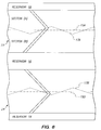
- Fig. 6 is an enlarged diagrammatic "unwrap" view of the Fig. 4 bearing unit illustrating the self-replenishing hydrodynamic pumping bearing patterns.
- Fig. 7 is an enlarged plan view of a balanced planar flow spiral groove thrust bearing pattern in accordance with principles of the present invention.
- Fig. 8 is an enlarged, diagrammatic view in elevation and section of a portion of a shaft and a housing forming a hydrodynamic bearing unit incorporating the Figs. 4 and 6 shaft bearings and the Fig. 7 thrust bearings in accordance with principles of the present invention.
- Fig. 3 illustrates a herringbone centrifugal pumping pattern for a hydrodynamic bearing in accordance with principles of the present invention.
- an alternating locus 17 alternates in a regular or periodic fashion about the circular central locus 15 which is perpendicular to an axis 20 of relative rotation of a hydrodynamic bearing unit including the shaft 12 and a mating housing (not shown in Fig. 3).
- the alternating locus 17 establishes the relative lengths of the two legs 10A and 10B forming each Vee-groove of the new pattern.
- a leg 10A1 is longer than another leg 10B1, whereas the reverse is true in the next Vee-groove where leg 10A2 is slightly shorter than leg 10B2.
- Fig. 4 illustrates four Vee-grooves 10-1, 10-2, 10-3, 10-4. These four grooves 10 extend from reservoirs 16 and 18 and have apexes along the alternating locus 17 (relative to the circular locus 15).
- the alternating locus line 17 dithers e.g. symmetrically about the circular locus 15, and the Vee-grooves 10 are arranged so that the sum of all local lubricant flows in the axial direction is zero.
- local net axial flow in the Fig. 4 example is as follows: Leg 10A1 is longer in length than leg 10B1 with resultant flow from reservoir 16 to reservoir 18.
- leg 10A2 is slightly longer than leg 10B2, and a smaller net local flow proceeds from reservoir 16 to reservoir 18.
- leg 10A3 is slightly shorter than leg 10B3, with a resultant slight net flow from reservoir 18 to reservoir 16.
- Leg 10A4 is shorter than leg 10B4, and a resultant larger net flow occurs from reservoir 18 to reservoir 16.
- This localized circulation thereby enables wear debris and lubricant residues, etc., to be flushed away from bearing surfaces, and enables lubricating liquid to be replenished with replacement lubricant displaced from the reservoirs 16 and 18 by the localized pumping action, and also prevents dirty or contaminated lubricating oil from becoming trapped within the bearing leading to lubricating liquid chemical breakdown and gumminess at the bearing surface.
- Fig. 5 illustrates a self-replenishing herringbone bearing pattern applied to two bearings 22 and 24 within a bearing assembly including the shaft 12 and a bearing sleeve 14.
- reservoir 16 is an interior reservoir for lubricating liquid
- reservoirs 18 form outer reservoirs for the liquid. Suitable seals, not forming a part of the present invention, are provided beyond the reservoirs 18 to prevent unwanted loss of lubricating liquid.
- the herringbone patterns are shown as formed on the shaft 12 in this example, it will be appreciated that these patterns can alternatively be formed on the raised mating surfaces of the sleeve 14 and achieve the desired self-replenishing hydrodynamic bearing.
- Fig. 6 shows a special case of the Fig. 5 bearing unit wherein the alternating locus lines 17 are out of phase with each other so that any axial force resulting from centrifugal pumping is balanced out around the bearing surfaces.
- the alternating locus line 17A of a top bearing pattern 22 has the same frequency and is opposite in phase with an alternating locus line 17B of a bottom bearing pattern 17B.
- Each alternating locus line 17A, 17B, is symmetrical about a bearing center locus 15A, 15B.
- the plate 50 includes a flat circular surface defining an outer reservoir 52, an interior reservoir 54 and a continuous curved spiral groove pattern or a discontinuous curve Vee-shape or chevron pattern in which the apex of each groove follows an undulating locus line 17 which dithers symmetrically about a central circular locus line 15.
- a radially outer leg 56A1 is slightly shorter than its inner leg 56B1 with net centrifugal pumping and flow from the inner reservoir 54 to the outer reservoir 52.
- an outer leg 56A2 is slightly longer than its inner leg 56B2, with net flow of lubricating liquid occurring from the outer reservoir 52 to the inner reservoir 54.
- the grooves are arranged so that each groove achieves localized flow and lubricating liquid replenishment while total global radial flow of lubricating liquid is zero.
- the circulation of lubricating liquid between the outer reservoir 52 and the inner reservoir 54 has the same replenishing effect as is achieved in the self-replenishing cylindrical herringbone patterns illustrated in Figs. 3-6.
- Fig. 8 shows a self replenishing hydrodynamic bearing unit 30 including two shaft bearings 22 and 24 as described in conjunction with Figs. 5-6 and two thrust bearings 50 as described in conjunction with Fig. 7.
- two wedge-shaped capillary seals 60 are provided at the outer peripheries of the shaft 12 and the sleeve 14 to provide self-containment of the lubricating liquid 32 illustrated herein by stippling.
- the lubricating liquid 32 may be any suitable lubricant for hydrodynamic bearings. While annular, diverging wall capillary seals 60 are shown in Fig. 8, other sealing arrangements are also preferred. In particular, a sealing arrangement as described in commonly assigned, copending U.S. Patent Application Serial No. , filed on the same date as this application and entitled: "A Self-Contained Hydrodynamic Bearing Unit", is preferred. The disclosure of that application is hereby incorporated by reference into this application. While the locus line 17 has been illustrated as curved and triangular, any suitable bearing pattern may be adopted, so long as it provides for localized flow within each bearing groove as well as minimizing global axial flow (in the example of shaft bearings) and minimizing global radial flow (in the example of thrust bearings).
- the shaft 12 and sleeve 14 should have compatible coefficients of thermal expansion in order to maintain a desired lubricant film thickness between the bearing surfaces of e.g. 3-7 microinches.
- the shaft 12 may be made of a stainless or carbon steel alloy and the sleeve made of a bronze alloy; or, the shaft 12 and sleeve 14 may both be made of carbon steel, with one or both elements being suitably hardened.
- the bearing surfaces are most preferably finished to an ANSI surface finish of approximately 8 micro inch root-mean-square, or better.
- the herringbone or Vee-shaped grooves are applied by conventional micro-machining operations involving a rotary spindle and cutter, and a fourth axis rotary table for chucking the shaft or thrust plate having the surface to be machined, both cooperatively operating under computer aided manufacturing control process, for example.
- Electro-discharge-machining (EDM) methods may also be employed.
- the spiral grooves on the thrust plate surface may be formed by machining, EDM, etching or coining processes.
- the lubricating liquid is most preferably a low evaporation rate, low thermal breakdown lubricating oil.
Landscapes
- Engineering & Computer Science (AREA)
- General Engineering & Computer Science (AREA)
- Mechanical Engineering (AREA)
- Chemical & Material Sciences (AREA)
- Oil, Petroleum & Natural Gas (AREA)
- Physics & Mathematics (AREA)
- Fluid Mechanics (AREA)
- Sliding-Contact Bearings (AREA)
Applications Claiming Priority (2)
| Application Number | Priority Date | Filing Date | Title |
|---|---|---|---|
| US278805 | 1994-07-22 | ||
| US08/278,805 US5407281A (en) | 1994-07-22 | 1994-07-22 | Self-replenishing hydrodynamic bearing |
Publications (2)
| Publication Number | Publication Date |
|---|---|
| EP0697534A2 true EP0697534A2 (de) | 1996-02-21 |
| EP0697534A3 EP0697534A3 (de) | 1996-09-25 |
Family
ID=23066446
Family Applications (1)
| Application Number | Title | Priority Date | Filing Date |
|---|---|---|---|
| EP95304664A Withdrawn EP0697534A3 (de) | 1994-07-22 | 1995-07-04 | Selbstauffüllendes hydrodynamisches Lager |
Country Status (3)
| Country | Link |
|---|---|
| US (1) | US5407281A (de) |
| EP (1) | EP0697534A3 (de) |
| JP (1) | JP3150878B2 (de) |
Cited By (2)
| Publication number | Priority date | Publication date | Assignee | Title |
|---|---|---|---|---|
| WO2001027483A1 (en) * | 1999-10-08 | 2001-04-19 | Toender Kristian | A slide bearing or slide sealing device |
| CN109372597A (zh) * | 2018-11-30 | 2019-02-22 | 江苏理工学院 | 一种可调式涡轮增压器 |
Families Citing this family (34)
| Publication number | Priority date | Publication date | Assignee | Title |
|---|---|---|---|---|
| US5558443A (en) * | 1994-07-22 | 1996-09-24 | Quantum Corporation | Shaft seal for hydrodynamic bearing unit |
| US5579579A (en) * | 1994-12-08 | 1996-12-03 | Quantum Corporation | Method for making precision self-contained hydrodynamic bearing assembly |
| US5533811A (en) * | 1995-02-14 | 1996-07-09 | Quantum Corporation | Hydrodynamic bearing having inverted surface tension seals |
| US5874793A (en) * | 1995-06-02 | 1999-02-23 | Ibiden Co., Ltd. | High speed rotor assembly |
| US5634724A (en) * | 1995-08-25 | 1997-06-03 | Quantum Corporation | Hydrodynamic bearing for spindle motor having high inertial load |
| US5516212A (en) * | 1995-09-18 | 1996-05-14 | Western Digital Corporation | Hydrodynamic bearing with controlled lubricant pressure distribution |
| US6010246A (en) * | 1995-10-25 | 2000-01-04 | Sankyo Seiki Mfg. Co., Ltd. | Hydrodynamic bearing apparatus and method of manufacturing it |
| GB2306583A (en) * | 1995-10-28 | 1997-05-07 | Daewoo Electronics Co Ltd | Lubricated journal bearing assembly |
| JP3732605B2 (ja) * | 1997-01-06 | 2006-01-05 | 光洋精工株式会社 | 密閉形スラスト動圧軸受 |
| US5847479A (en) * | 1997-04-15 | 1998-12-08 | Sae Magnetics (H.K.) Ltd. | Self-pressure-balanced hydrodynamic bearing spindle motor |
| JP3544098B2 (ja) * | 1997-05-19 | 2004-07-21 | 日本電産株式会社 | 動圧流体軸受装置 |
| US6427330B1 (en) * | 1997-10-07 | 2002-08-06 | Sankyo Seiki Mfg. Co., Ltd. | Method for forming a lubricant coating on a hydrodynamic bearing apparatus by electrode positioning |
| JP3184794B2 (ja) * | 1997-12-18 | 2001-07-09 | セイコーインスツルメンツ株式会社 | スピンドルモータ、及びスピンドルモータを回転体の駆動源とする回転体装置 |
| US6196722B1 (en) * | 1998-01-13 | 2001-03-06 | Matsushita Electric Industrial Co., Ltd. | Hydrodynamic bearing |
| EP1471274B1 (de) * | 1998-04-11 | 2006-08-09 | JTEKT Corporation | Geschlossenes dynamisches Drucklager mit Durchgangsöffnung |
| JP4043644B2 (ja) | 1999-05-06 | 2008-02-06 | 日本電産株式会社 | 動圧軸受装置の製造方法 |
| WO2001001003A1 (en) * | 1999-06-30 | 2001-01-04 | Matsushita Electric Industrial Co., Ltd. | Dynamic pressure type fluid bearing device and method of manufacturing the device |
| US20030185472A1 (en) * | 2002-03-13 | 2003-10-02 | Aiello Anthony Joseph | Single thrust bearing fluid dynamic bearing motor |
| US7213972B2 (en) * | 2002-07-01 | 2007-05-08 | Seagate Technology Llc | Non-recirculating conical fluid dynamic bearing for an electric motor |
| JP2004116754A (ja) * | 2002-09-30 | 2004-04-15 | Seiko Instruments Inc | 動圧軸受、モータ装置、及び塑性変形加工方法 |
| CN100357620C (zh) | 2004-08-14 | 2007-12-26 | 鸿富锦精密工业(深圳)有限公司 | 流体动压轴承 |
| WO2007111218A1 (ja) * | 2006-03-24 | 2007-10-04 | Ntn Corporation | 流体軸受装置 |
| JP4937619B2 (ja) * | 2006-03-24 | 2012-05-23 | Ntn株式会社 | 動圧軸受装置 |
| RU2336442C1 (ru) * | 2007-04-10 | 2008-10-20 | Федор Данилович Тихонов | Опора скольжения водяная |
| RU2347962C1 (ru) * | 2007-06-25 | 2009-02-27 | Федор Данилович Тихонов | Опора скольжения осевая водяная |
| CN101392799B (zh) * | 2007-09-21 | 2010-05-26 | 富准精密工业(深圳)有限公司 | 含油轴承密封结构和采用该含油轴承密封结构的风扇 |
| JP5155705B2 (ja) * | 2008-03-18 | 2013-03-06 | ミネベア株式会社 | 流体動圧軸受装置、スピンドルモータおよび流体動圧軸受装置の製造方法 |
| RU2382247C1 (ru) * | 2008-11-01 | 2010-02-20 | Федор Данилович Тихонов | Опора скольжения радиальная водяная |
| RU2389917C1 (ru) * | 2009-03-16 | 2010-05-20 | Федор Данилович Тихонов | Опора скольжения комбинированная (радиально-осевая) водяная |
| DE102009019170B4 (de) * | 2009-04-28 | 2013-10-31 | Minebea Co., Ltd. | Fluiddynamisches Lager |
| KR20130020374A (ko) * | 2011-08-19 | 2013-02-27 | 삼성전기주식회사 | 유체 동압 베어링 어셈블리 |
| KR20130074573A (ko) * | 2011-12-26 | 2013-07-04 | 삼성전기주식회사 | 유체 동압 베어링 어셈블리 및 이를 포함하는 모터 |
| US10774876B1 (en) * | 2019-04-25 | 2020-09-15 | Freudenberg-Nok General Partnership | Hydrodynamic thrust washers with pumping features for sparse lubrication applications |
| US11353057B2 (en) | 2019-12-03 | 2022-06-07 | Elliott Company | Journal and thrust gas bearing |
Citations (4)
| Publication number | Priority date | Publication date | Assignee | Title |
|---|---|---|---|---|
| US4557610A (en) | 1982-09-02 | 1985-12-10 | Matsushita Electric Industrial Co., Ltd. | Dynamic pressure type fluid bearing device |
| US4596474A (en) | 1984-06-13 | 1986-06-24 | U.S. Philips Corporation | Bearing system comprising two facing hydrodynamic bearings |
| US5112141A (en) | 1989-06-30 | 1992-05-12 | Matsushita Electric Industrial Co., Ltd. | Disk driving apparatus |
| US5246294A (en) | 1991-05-30 | 1993-09-21 | Digital Equipment Corporation | Flow-regulating hydrodynamic bearing |
Family Cites Families (9)
| Publication number | Priority date | Publication date | Assignee | Title |
|---|---|---|---|---|
| US3602555A (en) * | 1969-09-18 | 1971-08-31 | Singer General Precision | Journal bearing |
| NL7213192A (de) * | 1972-09-29 | 1974-04-02 | ||
| DE2624849C3 (de) * | 1976-06-03 | 1981-12-03 | Skf Kugellagerfabriken Gmbh, 8720 Schweinfurt | Selbstdruckerzeugendes Radialgleitlager |
| JPS5850321A (ja) * | 1981-09-18 | 1983-03-24 | Matsushita Electric Ind Co Ltd | 軸受装置 |
| JPH0630131B2 (ja) * | 1984-08-18 | 1994-04-20 | 松下電器産業株式会社 | 流体軸受シリンダ装置 |
| JPS60121308A (ja) * | 1984-08-21 | 1985-06-28 | Nippon Seiko Kk | 動圧形の複合軸受装置 |
| JPS6165905A (ja) * | 1984-09-10 | 1986-04-04 | Canon Inc | 動圧軸受装置 |
| JPH07113370B2 (ja) * | 1986-12-26 | 1995-12-06 | 松下電器産業株式会社 | 動圧型流体軸受 |
| JP2516967B2 (ja) * | 1987-04-30 | 1996-07-24 | 松下電器産業株式会社 | 軸受装置 |
-
1994
- 1994-07-22 US US08/278,805 patent/US5407281A/en not_active Expired - Lifetime
-
1995
- 1995-07-04 EP EP95304664A patent/EP0697534A3/de not_active Withdrawn
- 1995-07-21 JP JP18516395A patent/JP3150878B2/ja not_active Expired - Lifetime
Patent Citations (4)
| Publication number | Priority date | Publication date | Assignee | Title |
|---|---|---|---|---|
| US4557610A (en) | 1982-09-02 | 1985-12-10 | Matsushita Electric Industrial Co., Ltd. | Dynamic pressure type fluid bearing device |
| US4596474A (en) | 1984-06-13 | 1986-06-24 | U.S. Philips Corporation | Bearing system comprising two facing hydrodynamic bearings |
| US5112141A (en) | 1989-06-30 | 1992-05-12 | Matsushita Electric Industrial Co., Ltd. | Disk driving apparatus |
| US5246294A (en) | 1991-05-30 | 1993-09-21 | Digital Equipment Corporation | Flow-regulating hydrodynamic bearing |
Cited By (3)
| Publication number | Priority date | Publication date | Assignee | Title |
|---|---|---|---|---|
| WO2001027483A1 (en) * | 1999-10-08 | 2001-04-19 | Toender Kristian | A slide bearing or slide sealing device |
| CN109372597A (zh) * | 2018-11-30 | 2019-02-22 | 江苏理工学院 | 一种可调式涡轮增压器 |
| CN109372597B (zh) * | 2018-11-30 | 2021-05-18 | 江苏理工学院 | 一种可调式涡轮增压器 |
Also Published As
| Publication number | Publication date |
|---|---|
| EP0697534A3 (de) | 1996-09-25 |
| JPH0886311A (ja) | 1996-04-02 |
| US5407281A (en) | 1995-04-18 |
| JP3150878B2 (ja) | 2001-03-26 |
Similar Documents
| Publication | Publication Date | Title |
|---|---|---|
| US5407281A (en) | Self-replenishing hydrodynamic bearing | |
| US5558445A (en) | Self-contained hydrodynamic bearing unit and seals | |
| US6280090B1 (en) | Bearings and mechanical seals enhanced with microstructures | |
| US5634724A (en) | Hydrodynamic bearing for spindle motor having high inertial load | |
| JP2525216Y2 (ja) | 流体力学的ベアリング | |
| EP0623768B1 (de) | Labyrinth-Gasdichtung | |
| US5769604A (en) | Face seal device having high angular compliance | |
| KR930004677B1 (ko) | 베어링장치 | |
| US5588812A (en) | Implantable electric axial-flow blood pump | |
| US5716141A (en) | Precision self-contained hydrodynamic bearing assembly | |
| KR100234507B1 (ko) | 자체 가압식 저어널 베어링 조립체 | |
| US6629829B1 (en) | Vane type rotary machine | |
| EP0466076A2 (de) | Spiralrillengleitringdichtung | |
| US5052694A (en) | Hydrostatic face seal and bearing | |
| GB1590596A (en) | Hydrodynamic bearing | |
| EP1421287A2 (de) | Drucklager und verfahren zum lastausgleich | |
| JPH04331816A (ja) | 油膜軸受用ブシュ | |
| JPH11501112A (ja) | V字状オイルバリヤ溝を有する動力学的溝軸受 | |
| US6695480B1 (en) | Opposed flow seal/bearing assembly | |
| EP0258210B1 (de) | Hydraulisches gleitlager | |
| EP0697535A2 (de) | Hydrodynamische Lagereinheit | |
| EP0922873B1 (de) | Hydrodynamisches Wellenlager mit einem konzentrischen, aussenhydrostatischen Lager | |
| JPH0343028B2 (de) | ||
| CN1061420C (zh) | 具有保持器的液压轴承 | |
| US12018701B2 (en) | Hydraulic bearings and related devices, assemblies, and methods |
Legal Events
| Date | Code | Title | Description |
|---|---|---|---|
| PUAI | Public reference made under article 153(3) epc to a published international application that has entered the european phase |
Free format text: ORIGINAL CODE: 0009012 |
|
| AK | Designated contracting states |
Kind code of ref document: A2 Designated state(s): DE FR GB IT NL |
|
| PUAL | Search report despatched |
Free format text: ORIGINAL CODE: 0009013 |
|
| AK | Designated contracting states |
Kind code of ref document: A3 Designated state(s): DE FR GB IT NL |
|
| 17P | Request for examination filed |
Effective date: 19970303 |
|
| 17Q | First examination report despatched |
Effective date: 19981104 |
|
| GRAG | Despatch of communication of intention to grant |
Free format text: ORIGINAL CODE: EPIDOS AGRA |
|
| RAP1 | Party data changed (applicant data changed or rights of an application transferred) |
Owner name: QUANTUM CORPORATION |
|
| GRAG | Despatch of communication of intention to grant |
Free format text: ORIGINAL CODE: EPIDOS AGRA |
|
| GRAG | Despatch of communication of intention to grant |
Free format text: ORIGINAL CODE: EPIDOS AGRA |
|
| GRAH | Despatch of communication of intention to grant a patent |
Free format text: ORIGINAL CODE: EPIDOS IGRA |
|
| GRAG | Despatch of communication of intention to grant |
Free format text: ORIGINAL CODE: EPIDOS AGRA |
|
| GRAH | Despatch of communication of intention to grant a patent |
Free format text: ORIGINAL CODE: EPIDOS IGRA |
|
| GRAH | Despatch of communication of intention to grant a patent |
Free format text: ORIGINAL CODE: EPIDOS IGRA |
|
| STAA | Information on the status of an ep patent application or granted ep patent |
Free format text: STATUS: THE APPLICATION IS DEEMED TO BE WITHDRAWN |
|
| 18D | Application deemed to be withdrawn |
Effective date: 20030201 |