EP0697477A2 - Thread selecting device for weaving machine - Google Patents
Thread selecting device for weaving machine Download PDFInfo
- Publication number
- EP0697477A2 EP0697477A2 EP95101303A EP95101303A EP0697477A2 EP 0697477 A2 EP0697477 A2 EP 0697477A2 EP 95101303 A EP95101303 A EP 95101303A EP 95101303 A EP95101303 A EP 95101303A EP 0697477 A2 EP0697477 A2 EP 0697477A2
- Authority
- EP
- European Patent Office
- Prior art keywords
- signal
- needle
- thread
- detecting
- machine
- Prior art date
- Legal status (The legal status is an assumption and is not a legal conclusion. Google has not performed a legal analysis and makes no representation as to the accuracy of the status listed.)
- Granted
Links
Images


Classifications
-
- D—TEXTILES; PAPER
- D03—WEAVING
- D03C—SHEDDING MECHANISMS; PATTERN CARDS OR CHAINS; PUNCHING OF CARDS; DESIGNING PATTERNS
- D03C3/00—Jacquards
- D03C3/20—Electrically-operated jacquards
-
- D—TEXTILES; PAPER
- D03—WEAVING
- D03D—WOVEN FABRICS; METHODS OF WEAVING; LOOMS
- D03D51/00—Driving, starting, or stopping arrangements; Automatic stop motions
Definitions
- This invention relates to a thread selecting device whereby a weaving machine selects a vertical thread according to a design or pattern.
- a thread selecting device such as for example a jacquard is used to select a vertical thread according to the pattern.
- Tokkai Hei 3-90646 published by the Japanese Patent Office in 1991 for example discloses a device that uses an actuator of an electromagnetic solenoid driven by an electrical signal to select a thread.
- This thread selecting device is installed above the weaving machine, and comprises a knife which ascends and descends in synchronism with the operating cycles of the weaving machine. It further comprises a plurality of thread selecting units provided with a needle driven upwards by the knife, a hook that supports the needle in its raised position, and an electromagnetic solenoid that oscillates the hook between a position wherein the needle is supported and a position wherein the needle is released.
- the needle is connected to vertical threads via a number of mechanisms, a thread being selected when it is supported in its raised position by the hook, and deselected when it is released and descends.
- the knife ascends on each operating cycle of the weaving machine, and lifts the needle.
- the solenoid When the solenoid is energized in the raised position of the needle, the hook engages with the needle, and the needle remains supported by the hook after the knife descends.
- a required vertical thread may be selected from among a large number of candidate vertical threads.
- the controller that energizes the solenoids is programmed to shut off current to the solenoids at the time when operation of the weaving machine is stopped, thereby preventing the solenoids from overheating.
- this invention provides a thread selecting device for use with a weaving machine, comprising a needle for selecting a thread used in the machine according to a displacement of the needle, a mechanism for displacing the needle in synchronism with an operation of the weaving machine, an electromagnetic actuator for maintaining the needle in a predetermined position, and a mechanism for supplying energizing current to the electromagnetic actuator in conjunction with the machine operation.
- the device further comprises a mechanism for detecting an interruption of the machine operation, and a mechanism for oscillating the energizing current when the interruption is detected.
- the interruption detecting mechanism comprises a mechanism for detecting a rotation period of a shaft which rotates in synchronism with the machine operation and a mechanism for comparing the rotation period with a predetermined value.
- the rotation period detecting mechanism comprises for example a mechanism for generating a pulse at an interval proportional to the rotation period and a mechanism for detecting this interval
- the comparing mechanism comprises for example a mechanism for comparing the interval with a predetermined value.
- the supplying mechanism comprises a mechanism for detecting a rotation position of the shaft which rotates in synchronism with the machine operation and a mechanism for outputting a signal for permitting the energizing current supply only when the position is within a predetermined range.
- the interruption detecting mechanism preferably comprises a mechanism for determining if the permitting signal has continued for longer than a predetermined time.
- the interruption determining mechanism may comprises a mechanism for generating a pulse having a constant frequency, a mechanism for counting pulses emitted while the energizing permission continues and a mechanism for determining if the counted number of pulses has exceeded a predetermined value.
- the oscillating mechanism preferably comprises a mechanism for outputting an oscillating signal having a predetermined frequency when the machine operation has been interrupted and outputting a signal having a constant level at other times, a mechanism for outputting a signal being a logical product of the permitting signal and the signal output by the oscillating mechanism, and a mechanism for oscillating the energizing current based on the signal output by the outputting mechanism.
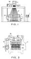
- Fig. 1 is a front view of a weaving machine and thread selecting device according to this invention.
- Fig. 2 is a schematic side view of the thread selecting device.
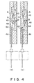
- Fig. 3 is a vertical sectional view of a thread selecting unit according to this invention.
- Fig. 4 is a vertical sectional view of the thread selecting unit viewed from a direction perpendicular to that of Fig. 3.
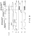
- Fig. 5 is a block diagram of a controller according to this invention.
- Fig. 6 is a timing chart showing a control operation of the controller, according to this invention.
- Fig. 7 is a timing chart showing a range wherein a solenoid can be energized, according to this invention.
- Fig. 8 is a block diagram of a controller according to a second embodiment of this invention.
- Fig. 9 is a timing chart showing a range wherein a solenoid can be energized according to the second embodiment of the invention.
- a thread selecting device 2 is installed above a weaving machine 3. It is driven by the weaving machine 3 via a main shaft 30 and shaft 34 connected to the main shaft 30.
- the shaft 34 is connected to knives 7A, 7B via a reflection sleeve 31, arm 32 and link mechanism 33 as shown in Fig. 2, these knives 7A, 7B ascending and descending alternately in synchronism with the weaving cycles of the weaving machine 3.
- a hook 6A is supported free to pivot on a hinge 43 above the knife 7A.
- a hook 6B is supported free to pivot on the hinge 43 alongside the hook 6A above the knife 7B.
- the hooks 6A, 6B can pivot independently of each other.
- a solenoid 5 is installed at an upper location in order to drive the hooks 6A, 6B.
- the hooks 6A, 6B are driven by the solenoid 5 via a mechanism shown in Fig. 4.
- the upper end of the hook 6A (6B) pushed by a spring 12 is in contact with the armature 9. Due to the attraction of the armature to the yoke 10, the hook 6A (6B) pivots against the force of the spring 12 so that a claw 60 at the bottom end is displaced to a forward position. On the other hand, when current to the solenoid 5 is stopped, the hook 6A (6B) is pivoted by the spring 12 as it pushes the armature 9 backward, and the claw 60 is displaced to a backward position.
- the thread 8 is raised via the pulley 41 when the other needle has ascended so that the thread 8 is selected. Further, when the hooks 6A, 6B are in their backward positions, one of the needles 4A, 4B descends when the other needle has ascended, hence the thread 8 is not pulled up and is deselected.
- One of the solenoids 5 is therefore sufficient for both of the hooks 6A, 6B, however separate solenoids may be provided for each hook.
- the supply and interruption of energizing current to each of the solenoids 5 is controlled by a controller 1 shown in Fig. 1.
- the controller 1 comprises a timer 13, comparison means 14, oscillating means 15, energizing permitting means 16, data transfer control means 17, signal processing means 18, storage device 19, AND gates 20, 21 and amplifying means 22, as shown in Fig. 5.
- the signal processing means 18, AND gate 21 and amplifying means 22 are provided for each solenoid 5.
- Thread selecting data i.e. data regarding which vertical thread is selected at which time, is stored in the storage means 19.
- the signal processing means 18 outputs a thread selecting signal Ds to the AND gate 20 based on this data according to a request signal Dt from the data transfer control means 17.
- a rotary encoder 11 that generates a pulse P at an interval proportional to a rotation period is attached to the main shaft 30 which rotates in synchronism with the operation of the weaving machine 3.
- This pulse P is input to the timer 13 of the controller 1 which measures its interval t .
- the timer 13 is reset at every pulse input. If this input does not occur, the interval t become larger and finally exceeds a predetermined value t 1.
- the comparison means 14 compares the interval t with the predetermined value t 1. If the interval t is greater than the predetermined value t 1, it is determined that the main shaft 30 has stopped, and a stop signal St is output to the oscillating means 15.
- the oscillating means 15 If the stop signal St is ON, the oscillating means 15 generates an output signal Ap having a predetermined frequency. On the other hand, if the stop signal St is OFF, a voltage signal (ON signal) having a predetermined level is output as the signal Ap .
- the pulse P is also input to the energizing permitting means 16. From the pulse P , the energizing permitting means 16 determines whether or not the needles 4A, 4B are raised so that they are able to engage with the claws 60 of the hooks 6A, 6B.
- the raised and lowered positions of the needles 4A, 4B correspond to predetermined rotation angles of the main shaft 30 as shown in Fig. 7.
- the means 16 can detect the raised and lowered positions of the needles 4A, 4B by counting the pulses P, and determines whether or not they are within limits where they can engage with the claws 60. When it is determined that they are in an engaging position, the energizing permitting means 16 outputs a drive permission signal Ao .
- the AND gate 20 When the signal Ap from the oscillating means 15 and the drive permission signal Ao from the energizing permitting means 16 are both ON, the AND gate 20 outputs an energizing signal As to the AND gate 21. Therefore, the energizing signal As is output when the signal Ap is generated and the signal Ao is ON.
- the AND gate 21 When the thread selecting signal Ds and the signal As from the AND gate 20 are both ON, the AND gate 21 outputs a drive signal So to the amplifying means 22. In this case, when the energizing signal As is output and the thread selecting signal Ds is ON, the drive signal So is also generated.
- the amplifying means 22 outputs the drive signal So to the solenoid 5 as an oscillating current amplified to a suitable level for energizing the solenoid 5.
- the pulse P from the rotary encoder 11 is output with a predetermined period corresponding to the rotation of the main shaft 30. Also, when the rotation angle of the main shaft 30 is such that the needle can engage with the hook 6A (6B), the drive permission signal Ao has the high level (ON) shown in the figure.
- the signal Ap from the oscillating means 15 always has the high level shown in the figure, so the output signal As from the AND gate 20 also has a high level.
- the thread selecting signal Ds is output from the signal processing means 18, the drive signal output from the AND gate 21 is ON, i.e. it has a high level.
- the solenoid 5 is then energized by the drive signal So amplified by the amplifying means 22, and the hook 6A (6B) engages with the needle 4A (4B) as shown in Figs. 3, 4.
- the hook 6A engages with the needle 4A as shown in Fig. 3(a)
- the thread 8 is pulled up via the pulley 41 when the needle 4B ascends as shown in Fig. 3(b), and the thread 8 is thereby selected.
- the energizing permitting means 16 switches the drive permission signal Ao to OFF.
- the outputs from the AND gates 20, 21 then both drop to low level (OFF), the drive signal So drops to low level, and the energizing of the solenoid 5 is stopped.
- the thread selecting signal Ds is OFF, the drive signal So is permanently OFF regardless of the drive permission signal Ao , so the thread 8 is not selected. During operation of the weaving machine 3, therefore, the thread 8 is selected according to the thread selecting signal Ds .
- the signals output by the AND gates 20 and 21 also oscillate.
- the solenoid 5 therefore switches alternately ON and OFF with a predetermined frequency, and is intermittently energized.
- the oscillating means 15 If operation of the weaving machine 3 stops at a time Td when the drive permission signal Ao is OFF, the oscillating means 15 generates the signal Ap from a time Te when the interval t exceeds the set time t 1. In this case, however, as the drive permission signal Ao is OFF, the signals As , So output by the AND gates 20, 21 are both OFF, and the solenoid 5 is not energized.
- a rotation sensor for detecting the rotation speed of the shaft 34, and an angle sensor for detecting the rotation angle of the shaft 34 corresponding to the energizing permission range shown in Fig. 7, may be provided instead of the rotary encoder 11 as rotation detection means.
- Fig. 8 shows another embodiment of this invention concerning the structure of the controller.
- the controller 1 comprises a pulse generator 23, counter 24 and comparison means 25 instead of the timer 13 and comparison means 14.
- the pulse generator 23 generates a pulse at an interval proportional to the rotation period of the shaft 30.
- the counter 24 counts the pulses after the drive permission signal Ao from the energizing permitting means 16 is ON so as to obtain a count number N , and resets the count number N when the energizing permission signal Ao is OFF.
- the comparison means 25 outputs a stop signal St when the count number N exceeds a set value N 1.
- the counter 24 When the weaving machine 3 stops at a time Tc when the drive permission signal Ao and thread selecting signal Ds are both ON and the solenoid 5 is energized, the counter 24 has counted the pulses from when the drive permission signal Ao is ON. At a time Td when the count number N exceeds the set value N 1, the comparison means 25 switches the stop signal St to ON, and the oscillating means 15 generates the signal Ap with a predetermined frequency.
- the signals As and So output by the AND gates 20, 21 are both oscillated, and the solenoid 5 is intermittently energized at a predetermined frequency. Overheating due to energizing current is therefore prevented while the solenoid 5 supports the needle 4A or 4B.
- the shaft 34 resumes rotation, the drive permission signal Ao switches OFF and the count number N of the counter 24 is reset.
- the oscillating means 15 therefore stops the oscillation of the signal Ap , the signal Ap thereafter being maintained at a high level.
- the weaving machine 3 is determined to have stopped operation by counting the pulses from the time when the drive permission signal Ao changes. This makes it unnecessary to directly detect the rotation speed or period of the main shaft 30 or shaft 34, so the construction of the device is simpler than that of the aforesaid first embodiment.
Abstract
Description
- This invention relates to a thread selecting device whereby a weaving machine selects a vertical thread according to a design or pattern.
- In a weaving machine having a function for weaving a specific design or pattern, a thread selecting device such as for example a jacquard is used to select a vertical thread according to the pattern.
- Tokkai Hei 3-90646 published by the Japanese Patent Office in 1991 for example discloses a device that uses an actuator of an electromagnetic solenoid driven by an electrical signal to select a thread.
- This thread selecting device is installed above the weaving machine, and comprises a knife which ascends and descends in synchronism with the operating cycles of the weaving machine. It further comprises a plurality of thread selecting units provided with a needle driven upwards by the knife, a hook that supports the needle in its raised position, and an electromagnetic solenoid that oscillates the hook between a position wherein the needle is supported and a position wherein the needle is released. The needle is connected to vertical threads via a number of mechanisms, a thread being selected when it is supported in its raised position by the hook, and deselected when it is released and descends.
- The knife ascends on each operating cycle of the weaving machine, and lifts the needle. When the solenoid is energized in the raised position of the needle, the hook engages with the needle, and the needle remains supported by the hook after the knife descends.
- On the other hand, when the solenoid is not energized the hook does not engage with the needle, and the needle descends together with the knife.
- Therefore, by selectively supplying an energizing current to the solenoid, a required vertical thread may be selected from among a large number of candidate vertical threads.
- When a horizontal or vertical thread breaks during operation of the weaving machine, operation may have to be stopped in order to recover from the accident. However, if this is done while the solenoid is still energized, the solenoid may overheat and be damaged.
- Therefore, the controller that energizes the solenoids is programmed to shut off current to the solenoids at the time when operation of the weaving machine is stopped, thereby preventing the solenoids from overheating.
- However, if current to the solenoids is shut off, all the needles descend to their deselecting positions. Alter operation is restarted, the hooks driven by the solenoids do not immediately follow the ascending needles, so that the initial selection of vertical threads is sometimes incorrect.
- If the operation of the weaving machine is just beginning, there is no problem even if the initial selection of vertical threads is not correct. However, if operation is stopped while a pattern or design is being woven and the wrong thread is selected when operation resumes, the pattern or design will be spoiled.
- It is therefore an object of this invention to maintain a needle in a predetermined position while preventing overheating of a solenoid when operation of a weaving machine is interrupted.
- It is a further object of this invention to precisely determine when operation of a weaving machine has stopped.
- In order to achieve the above objects, this invention provides a thread selecting device for use with a weaving machine, comprising a needle for selecting a thread used in the machine according to a displacement of the needle, a mechanism for displacing the needle in synchronism with an operation of the weaving machine, an electromagnetic actuator for maintaining the needle in a predetermined position, and a mechanism for supplying energizing current to the electromagnetic actuator in conjunction with the machine operation. The device further comprises a mechanism for detecting an interruption of the machine operation, and a mechanism for oscillating the energizing current when the interruption is detected.
- It is preferable that the interruption detecting mechanism comprises a mechanism for detecting a rotation period of a shaft which rotates in synchronism with the machine operation and a mechanism for comparing the rotation period with a predetermined value.
- In this case, the rotation period detecting mechanism comprises for example a mechanism for generating a pulse at an interval proportional to the rotation period and a mechanism for detecting this interval, and the comparing mechanism comprises for example a mechanism for comparing the interval with a predetermined value.
- It is also preferable that the supplying mechanism comprises a mechanism for detecting a rotation position of the shaft which rotates in synchronism with the machine operation and a mechanism for outputting a signal for permitting the energizing current supply only when the position is within a predetermined range.
- In this case, the interruption detecting mechanism preferably comprises a mechanism for determining if the permitting signal has continued for longer than a predetermined time.
- Alternatively, the interruption determining mechanism may comprises a mechanism for generating a pulse having a constant frequency, a mechanism for counting pulses emitted while the energizing permission continues and a mechanism for determining if the counted number of pulses has exceeded a predetermined value.
- The oscillating mechanism preferably comprises a mechanism for outputting an oscillating signal having a predetermined frequency when the machine operation has been interrupted and outputting a signal having a constant level at other times, a mechanism for outputting a signal being a logical product of the permitting signal and the signal output by the oscillating mechanism, and a mechanism for oscillating the energizing current based on the signal output by the outputting mechanism.
- The details as well as other features and advantages of this invention are set forth in the remainder of the specification and are shown in the accompanying drawings.
- Fig. 1 is a front view of a weaving machine and thread selecting device according to this invention.
- Fig. 2 is a schematic side view of the thread selecting device.
- Fig. 3 is a vertical sectional view of a thread selecting unit according to this invention.
- Fig. 4 is a vertical sectional view of the thread selecting unit viewed from a direction perpendicular to that of Fig. 3.
- Fig. 5 is a block diagram of a controller according to this invention.
- Fig. 6 is a timing chart showing a control operation of the controller, according to this invention.
- Fig. 7 is a timing chart showing a range wherein a solenoid can be energized, according to this invention.
- Fig. 8 is a block diagram of a controller according to a second embodiment of this invention.
- Fig. 9 is a timing chart showing a range wherein a solenoid can be energized according to the second embodiment of the invention.
- Referring to Fig. 1 of the drawings, a
thread selecting device 2 is installed above aweaving machine 3. It is driven by theweaving machine 3 via amain shaft 30 andshaft 34 connected to themain shaft 30. - The
shaft 34 is connected toknives reflection sleeve 31,arm 32 andlink mechanism 33 as shown in Fig. 2, theseknives weaving machine 3. - When the
knives needles holes 40 are formed in the upper ends of theneedles operating thread 42, from which acommon pulley 41 is suspended, is connected to the lower ends, and avertical thread 8 is connected to thepulley 41. Therefore, when both theneedles vertical thread 8 is pulled up via thepulley 41 and is selected. Conversely, when either of theneedles thread 8 is not pulled up and is deselected. As theknives needles - A
hook 6A is supported free to pivot on ahinge 43 above theknife 7A. Likewise, ahook 6B is supported free to pivot on thehinge 43 alongside thehook 6A above theknife 7B. Thehooks solenoid 5 is installed at an upper location in order to drive thehooks - The
hooks solenoid 5 via a mechanism shown in Fig. 4. - When energized, the
solenoid 5 pulls anarmature 9 toward ayoke 10. - The upper end of the
hook 6A (6B) pushed by aspring 12 is in contact with thearmature 9. Due to the attraction of the armature to theyoke 10, thehook 6A (6B) pivots against the force of thespring 12 so that aclaw 60 at the bottom end is displaced to a forward position. On the other hand, when current to thesolenoid 5 is stopped, thehook 6A (6B) is pivoted by thespring 12 as it pushes thearmature 9 backward, and theclaw 60 is displaced to a backward position. - When the
solenoid 5 is energized in the raised position of theneedle 4A shown in Fig. 7, thehook 6A pivots so that theclaw 60 enters theengaging hole 40 of theneedle 4A as shown in Fig. 4(b). Therefore, even when theknife 7A has descended, theneedle 4A remains in its raised position. The same is true of thehook 6B andneedle 4B. - Provided that either the
needle thread 8 is raised via thepulley 41 when the other needle has ascended so that thethread 8 is selected. Further, when thehooks needles thread 8 is not pulled up and is deselected. One of thesolenoids 5 is therefore sufficient for both of thehooks - The supply and interruption of energizing current to each of the
solenoids 5 is controlled by a controller 1 shown in Fig. 1. - The controller 1 comprises a
timer 13, comparison means 14, oscillating means 15, energizing permitting means 16, data transfer control means 17, signal processing means 18,storage device 19, ANDgates - The signal processing means 18, AND
gate 21 and amplifying means 22 are provided for eachsolenoid 5. - Thread selecting data, i.e. data regarding which vertical thread is selected at which time, is stored in the storage means 19. The signal processing means 18 outputs a thread selecting signal Ds to the AND
gate 20 based on this data according to a request signal Dt from the data transfer control means 17. - A
rotary encoder 11 that generates a pulse P at an interval proportional to a rotation period is attached to themain shaft 30 which rotates in synchronism with the operation of the weavingmachine 3. This pulse P is input to thetimer 13 of the controller 1 which measures its interval t. Thetimer 13 is reset at every pulse input. If this input does not occur, the interval t become larger and finally exceeds a predetermined value t₁. - The comparison means 14 compares the interval t with the predetermined value t₁. If the interval t is greater than the predetermined value t₁, it is determined that the
main shaft 30 has stopped, and a stop signal St is output to the oscillating means 15. - If the stop signal St is ON, the oscillating means 15 generates an output signal Ap having a predetermined frequency. On the other hand, if the stop signal St is OFF, a voltage signal (ON signal) having a predetermined level is output as the signal Ap.
- The pulse P is also input to the energizing permitting means 16. From the pulse P, the energizing permitting means 16 determines whether or not the
needles claws 60 of thehooks needles main shaft 30 as shown in Fig. 7. As the pulse P is output for each predetermined rotation angle, therefore, themeans 16 can detect the raised and lowered positions of theneedles claws 60. When it is determined that they are in an engaging position, the energizing permitting means 16 outputs a drive permission signal Ao. - When the signal Ap from the oscillating means 15 and the drive permission signal Ao from the energizing permitting means 16 are both ON, the AND
gate 20 outputs an energizing signal As to the ANDgate 21. Therefore, the energizing signal As is output when the signal Ap is generated and the signal Ao is ON. - When the thread selecting signal Ds and the signal As from the AND
gate 20 are both ON, the ANDgate 21 outputs a drive signal So to the amplifying means 22. In this case, when the energizing signal As is output and the thread selecting signal Ds is ON, the drive signal So is also generated. The amplifying means 22 outputs the drive signal So to thesolenoid 5 as an oscillating current amplified to a suitable level for energizing thesolenoid 5. - During the operation of the weaving
machine 3, as shown in Fig. 6, the pulse P from therotary encoder 11 is output with a predetermined period corresponding to the rotation of themain shaft 30. Also, when the rotation angle of themain shaft 30 is such that the needle can engage with thehook 6A (6B), the drive permission signal Ao has the high level (ON) shown in the figure. - During the operation of the weaving
machine 3, the signal Ap from the oscillating means 15 always has the high level shown in the figure, so the output signal As from the ANDgate 20 also has a high level. - In this situation, when the thread selecting signal Ds is output from the signal processing means 18, the drive signal output from the AND
gate 21 is ON, i.e. it has a high level. Thesolenoid 5 is then energized by the drive signal So amplified by the amplifying means 22, and thehook 6A (6B) engages with theneedle 4A (4B) as shown in Figs. 3, 4. For example, when thehook 6A engages with theneedle 4A as shown in Fig. 3(a), thethread 8 is pulled up via thepulley 41 when theneedle 4B ascends as shown in Fig. 3(b), and thethread 8 is thereby selected. - When the
main shaft 30 rotates further so that it is outside the energizing permission limits shown in Fig. 7, the energizing permitting means 16 switches the drive permission signal Ao to OFF. The outputs from the ANDgates solenoid 5 is stopped. - On the other hand, when the thread selecting signal Ds is OFF, the drive signal So is permanently OFF regardless of the drive permission signal Ao, so the
thread 8 is not selected. During operation of the weavingmachine 3, therefore, thethread 8 is selected according to the thread selecting signal Ds. - However, if the operation of the weaving
machine 3 stops at a time Ta as shown in Fig. 6 due for example to a breakage of a horizontal thread, generation of pulses by the rotary encoder ceases, and the interval t measured by thetimer 13 increases. When the interval t does not exceed a set value t₁, the signal Ap remains ON, the drive signal So is output according to the drive permission signal Ap and the thread selecting signal Ds, and thesolenoid 5 is energized. However, when the interval t exceeds the set value t₁ at a time Tb, the stop signal St output by the comparison means 14 changes to ON, and the signal Ap output by the oscillating means 15 begins oscillating. - Due to the oscillation of the signal Ap, the signals output by the AND
gates solenoid 5 therefore switches alternately ON and OFF with a predetermined frequency, and is intermittently energized. - Even when energizing of the
solenoid 5 instantaneously stops, it does not lose its attractive force simultaneously, its attractive force merely declining according to an intrinsic time constant. Therefore, if the time from when the drive signal So is OFF to when it is ON, i.e. the frequency of the oscillating means 15, is set within certain limits such that thesolenoid 5 does not lose its attraction for theneedles solenoid 5 can be prevented while theneedles - When the damage due to the broken horizontal thread is repaired and operation of the weaving
machine 3 is resumed at a time Tc, the interval t measured by thetimer 13 once again becomes less than the set value t₁. The stop signal St output by the comparison means 14 is therefore again OFF, the output Ap of the oscillating means is again at a high level, and the drive signal So of thesolenoid 5 is once again output continuously at a constant level. - If operation of the weaving
machine 3 stops at a time Td when the drive permission signal Ao is OFF, the oscillating means 15 generates the signal Ap from a time Te when the interval t exceeds the set time t₁. In this case, however, as the drive permission signal Ao is OFF, the signals As, So output by the ANDgates solenoid 5 is not energized. - In the aforesaid embodiment, a rotation sensor for detecting the rotation speed of the
shaft 34, and an angle sensor for detecting the rotation angle of theshaft 34 corresponding to the energizing permission range shown in Fig. 7, may be provided instead of therotary encoder 11 as rotation detection means. - Fig. 8 shows another embodiment of this invention concerning the structure of the controller.
- In this case, the controller 1 comprises a
pulse generator 23, counter 24 and comparison means 25 instead of thetimer 13 and comparison means 14. Thepulse generator 23 generates a pulse at an interval proportional to the rotation period of theshaft 30. The counter 24 counts the pulses after the drive permission signal Ao from the energizing permitting means 16 is ON so as to obtain a count number N, and resets the count number N when the energizing permission signal Ao is OFF. The comparison means 25 outputs a stop signal St when the count number N exceeds a set value N₁. - When the weaving
machine 3 stops in a time span Ta - Tb during which the drive permission signal Ao is OFF, as shown in Fig. 9, thecounter 24 does not operate, and the signal Ap output by the oscillating means 15 is maintained at a constant level. On the other hand, the thread selecting signal Ds from the signal processing means 18 is OFF during this time, so the drive signal So output by the ANDgate 21 is also OFF, and thesolenoid 5 remains un-energized. - When the weaving
machine 3 stops at a time Tc when the drive permission signal Ao and thread selecting signal Ds are both ON and thesolenoid 5 is energized, thecounter 24 has counted the pulses from when the drive permission signal Ao is ON. At a time Td when the count number N exceeds the set value N₁, the comparison means 25 switches the stop signal St to ON, and the oscillating means 15 generates the signal Ap with a predetermined frequency. - As a result, the signals As and So output by the AND
gates solenoid 5 is intermittently energized at a predetermined frequency. Overheating due to energizing current is therefore prevented while thesolenoid 5 supports theneedle - At a time Te when the weaving
machine 3 resumes operation, theshaft 34 resumes rotation, the drive permission signal Ao switches OFF and the count number N of thecounter 24 is reset. The oscillating means 15 therefore stops the oscillation of the signal Ap, the signal Ap thereafter being maintained at a high level. - According to this embodiment, the weaving
machine 3 is determined to have stopped operation by counting the pulses from the time when the drive permission signal Ao changes. This makes it unnecessary to directly detect the rotation speed or period of themain shaft 30 orshaft 34, so the construction of the device is simpler than that of the aforesaid first embodiment. - It is of course moreover possible to determine when the weaving
machine 3 has stopped also by measuring the time from when the drive permission signal Ao changes regardless of the number of pulses counted. - The embodiments of this invention in which an exclusive property or privilege is claimed are defined as follows:
Claims (6)
- A thread selecting device (2) for use with a weaving machine (3), comprising a needle (4A, 4B) for selecting a thread (8) used in said machine (3) according to a displacement of said needle (4A, 4B), means (7A,7B) for displacing said needle (4A, 4B) in synchronism with an operation of said machine (3), an electromagnetic actuator (5) for maintaining said needle (4A, 4B) in a predetermined position, and means (11, 16, 17, 18, 19, 22) for supplying energizing current to said electromagnetic actuator (5) in conjunction with said machine operation, characterized in that said device (2) further comprises:
means (11, 13, 14, 23, 24, 25) for detecting an interruption of said machine operation, and
means (15, 20, 21) for oscillating said energizing current when said interruption is detected. - A thread selecting device (2) as defined in claim 1, wherein said detecting means (11, 13, 14, 23, 24, 25) comprises means (11, 13) for detecting a rotation period of a shaft (30, 34) which rotates in synchronism with said machine operation, and means (14) for comparing said rotation period with a predetermined value.
- A thread selecting device (2) as defined in claim 2, wherein said rotation period detecting means (11, 13) comprises means (11) for generating a pulse at an interval proportional to said rotation period and means (13) for detecting said interval, and wherein said comparing means (14) comprises means for comparing said interval with a predetermined value.
- A thread selecting device (2) as defined in claim 1, wherein said supplying means (11, 16, 17, 18, 19, 22) comprises means (11) for detecting a rotation position of a shaft (30, 34) which rotates in synchronism with said machine operation and means (16) for outputting a signal for permitting said energizing current supply only when said position is within a predetermined range, and wherein said interruption detecting means (11, 13, 14, 23, 24, 25) comprises means (14) for determining if said permitting signal has continued for longer than a predetermined time.
- A thread selecting device (2) as defined in claim 1, wherein said supplying means (11, 16, 17, 18, 19, 22) comprises means (11) for detecting a rotation position of a shaft (30, 34) which rotates in synchronism with said machine operation and means (16) for outputting a signal for permitting said energizing current supply only when said detected position is within a predetermined range, and wherein said interruption determining means (11, 13, 14, 23, 24, 25) comprises means (23) for generating a pulse having a constant frequency, means (24) for counting pulses emitted while said energizing permission continues, and means (25) for determining if the counted number of pulses has exceeded a predetermined value.
- A thread selecting device (2) as defined in claim 1, wherein said supplying means comprises means (11) for detecting a rotation position of a shaft (30, 34) which rotates in synchronism with said machine operation and means (16) for outputting a signal for permitting said energizing current supply only when said position is within a predetermined range, and wherein said oscillating means (15, 20, 21) comprises means (15) for outputting an oscillating signal having a predetermined frequency when said machine operation has been interrupted and outputting a signal having a constant level at other times, means (20) for outputting a signal being a logical product of said permitting signal and the signal output by said oscillating means (15), and means (21) for oscillating said energizing current based on said signal output by said outputting means (20).
Applications Claiming Priority (3)
| Application Number | Priority Date | Filing Date | Title |
|---|---|---|---|
| JP19429794 | 1994-08-18 | ||
| JP19429794A JP3373665B2 (en) | 1994-08-18 | 1994-08-18 | Warp selection device of loom |
| JP194297/94 | 1994-08-18 |
Publications (3)
| Publication Number | Publication Date |
|---|---|
| EP0697477A2 true EP0697477A2 (en) | 1996-02-21 |
| EP0697477A3 EP0697477A3 (en) | 1997-09-03 |
| EP0697477B1 EP0697477B1 (en) | 2000-05-24 |
Family
ID=16322258
Family Applications (1)
| Application Number | Title | Priority Date | Filing Date |
|---|---|---|---|
| EP19950101303 Expired - Lifetime EP0697477B1 (en) | 1994-08-18 | 1995-01-31 | Thread selecting device for weaving machine |
Country Status (3)
| Country | Link |
|---|---|
| EP (1) | EP0697477B1 (en) |
| JP (1) | JP3373665B2 (en) |
| DE (1) | DE69517104T2 (en) |
Cited By (7)
| Publication number | Priority date | Publication date | Assignee | Title |
|---|---|---|---|---|
| EP0781878A1 (en) * | 1995-12-26 | 1997-07-02 | Kayaba Kogyo Kabushiki Kaisha | Weaving machine thread selector |
| EP0801161A1 (en) * | 1996-04-10 | 1997-10-15 | N.V. Michel Van de Wiele | Shed forming device for a textile machine |
| GB2320259A (en) * | 1996-12-10 | 1998-06-17 | Mayer Textilmaschf | Electromagnetically-operating jacquard control device |
| US5813441A (en) * | 1996-04-10 | 1998-09-29 | N.V. Michel Van De Wiele | Shed forming device for a textile machine with actuator means |
| EP1302575A2 (en) * | 2001-10-10 | 2003-04-16 | Lindauer Dornier Gesellschaft M.B.H | Method for controlling the actuating elements of a Jacquard machine combined with a weaving loom |
| US6834681B2 (en) | 2001-10-10 | 2004-12-28 | Staubli Faverges | Method for controlling the shed in a loom with mechanical weft insertion |
| CN102066636B (en) * | 2008-04-16 | 2012-06-27 | 苏进守 | Thread feeding method, warp thread feeding method, thread feeder and weaving method |
Citations (5)
| Publication number | Priority date | Publication date | Assignee | Title |
|---|---|---|---|---|
| FR2587045A1 (en) * | 1985-09-06 | 1987-03-13 | Staubli Verdol | DEVICE FOR FORMING A CROWD IN A WEAVING MATERIAL COMPRISING A TILTING RETAINING HOOK |
| FR2625515A1 (en) * | 1988-01-05 | 1989-07-07 | Textima Veb K | JACQUARD MECHANICS WITH ELECTROMAGNETIC CONTROL OF THE SELECTION OF THE DECKS, PARTICULARLY FOR A WEAVING |
| FR2627514A1 (en) * | 1988-02-23 | 1989-08-25 | Textima Veb K | ELECTROMAGNETIC CONTROL OF SELECTION OF THE PLATES FOR JACQUARD MECHANICS OF A WEAVING |
| EP0439440A1 (en) * | 1990-01-23 | 1991-07-31 | Benedetto Bobbio | Computer controlled modular electromagnetic device for driving warp yarns for making figured fabrics |
| EP0494044A1 (en) * | 1991-01-03 | 1992-07-08 | Yu Hsiu Hsia Cheng | A heald retention system for a jacquard system |
-
1994
- 1994-08-18 JP JP19429794A patent/JP3373665B2/en not_active Expired - Fee Related
-
1995
- 1995-01-31 EP EP19950101303 patent/EP0697477B1/en not_active Expired - Lifetime
- 1995-01-31 DE DE1995617104 patent/DE69517104T2/en not_active Expired - Fee Related
Patent Citations (5)
| Publication number | Priority date | Publication date | Assignee | Title |
|---|---|---|---|---|
| FR2587045A1 (en) * | 1985-09-06 | 1987-03-13 | Staubli Verdol | DEVICE FOR FORMING A CROWD IN A WEAVING MATERIAL COMPRISING A TILTING RETAINING HOOK |
| FR2625515A1 (en) * | 1988-01-05 | 1989-07-07 | Textima Veb K | JACQUARD MECHANICS WITH ELECTROMAGNETIC CONTROL OF THE SELECTION OF THE DECKS, PARTICULARLY FOR A WEAVING |
| FR2627514A1 (en) * | 1988-02-23 | 1989-08-25 | Textima Veb K | ELECTROMAGNETIC CONTROL OF SELECTION OF THE PLATES FOR JACQUARD MECHANICS OF A WEAVING |
| EP0439440A1 (en) * | 1990-01-23 | 1991-07-31 | Benedetto Bobbio | Computer controlled modular electromagnetic device for driving warp yarns for making figured fabrics |
| EP0494044A1 (en) * | 1991-01-03 | 1992-07-08 | Yu Hsiu Hsia Cheng | A heald retention system for a jacquard system |
Cited By (12)
| Publication number | Priority date | Publication date | Assignee | Title |
|---|---|---|---|---|
| EP0781878A1 (en) * | 1995-12-26 | 1997-07-02 | Kayaba Kogyo Kabushiki Kaisha | Weaving machine thread selector |
| EP0801161A1 (en) * | 1996-04-10 | 1997-10-15 | N.V. Michel Van de Wiele | Shed forming device for a textile machine |
| BE1010133A3 (en) * | 1996-04-10 | 1998-01-06 | Wiele Michel Van De Nv | Gaap training device for a textile machine. |
| US5813441A (en) * | 1996-04-10 | 1998-09-29 | N.V. Michel Van De Wiele | Shed forming device for a textile machine with actuator means |
| US5819813A (en) * | 1996-04-10 | 1998-10-13 | N.V. Michel Van De Wiele | Shed forming device with separate selection and pulley modules |
| GB2320259A (en) * | 1996-12-10 | 1998-06-17 | Mayer Textilmaschf | Electromagnetically-operating jacquard control device |
| US5860454A (en) * | 1996-12-10 | 1999-01-19 | Karl Mayer Textilmachinenfabrik Gmbh | Electromagnetically-operating Jacquard control device |
| EP1302575A2 (en) * | 2001-10-10 | 2003-04-16 | Lindauer Dornier Gesellschaft M.B.H | Method for controlling the actuating elements of a Jacquard machine combined with a weaving loom |
| EP1302575A3 (en) * | 2001-10-10 | 2003-07-30 | Lindauer Dornier Gesellschaft M.B.H | Method for controlling the actuating elements of a Jacquard machine combined with a weaving loom |
| US6834681B2 (en) | 2001-10-10 | 2004-12-28 | Staubli Faverges | Method for controlling the shed in a loom with mechanical weft insertion |
| US6863091B2 (en) | 2001-10-10 | 2005-03-08 | Staubli Faverges | Method for controlling the shed in a loom with fluidic weft insertion |
| CN102066636B (en) * | 2008-04-16 | 2012-06-27 | 苏进守 | Thread feeding method, warp thread feeding method, thread feeder and weaving method |
Also Published As
| Publication number | Publication date |
|---|---|
| DE69517104T2 (en) | 2000-09-21 |
| EP0697477B1 (en) | 2000-05-24 |
| JP3373665B2 (en) | 2003-02-04 |
| JPH0860481A (en) | 1996-03-05 |
| EP0697477A3 (en) | 1997-09-03 |
| DE69517104D1 (en) | 2000-06-29 |
Similar Documents
| Publication | Publication Date | Title |
|---|---|---|
| US4195500A (en) | Automatic washing machine | |
| JP4204274B2 (en) | Bobbin thread monitoring device for lockstitch sewing machines | |
| EP0697477B1 (en) | Thread selecting device for weaving machine | |
| JP2556658B2 (en) | A method for detecting errors in textile webs. | |
| KR100276737B1 (en) | Control device and method of automatic ice maker | |
| EP0107110A1 (en) | Yarn storing, feeding and measuring device | |
| JPH05212186A (en) | Bobbin thread monitoring method and apparatus for stitch forming apparatus | |
| US4196685A (en) | Thread abnormality detection utilizing integrator and comparator in conjunction with rotary thread tension disk | |
| EP0131772B1 (en) | Circuit for detecting the failure of a step motor to respond to energization commands | |
| KR100198903B1 (en) | Monitoring apparatus | |
| US4627474A (en) | Yarn storing, feeding and measuring device | |
| JPH05222637A (en) | Apparatus for detecting running of yarn and displaying breakage of yarn by signal | |
| EP0122962B1 (en) | Weft inserting apparatus for jet looms | |
| BE1001919A3 (en) | Airjet WITH IMPROVED POWER SUPPLY FOR THE IMPACT WIRES. | |
| BE1027383B1 (en) | DEVICE AND METHOD FOR DETECTING DEVIATIONS IN POLAR FORMATION IN A LIFE | |
| US5064302A (en) | Temperature control in a wire dot printer | |
| RU2072009C1 (en) | Apparatus for automatic changing of position of layer upper part during transition state upon loom stop | |
| US4545314A (en) | Control system for sewing machines | |
| US6643562B2 (en) | Position determining apparatus for coordinate machine | |
| EP1331295A2 (en) | Method and apparatus for preventing weft bars in a loom | |
| EP0781878B1 (en) | Weaving machine thread selector | |
| EP0879311B1 (en) | System and method for controlling the stopping point of a tufting machine at a preset stop step in a carpet stitch pattern | |
| EP0724032A1 (en) | Thread selecting device for weaving machine | |
| JP2838227B2 (en) | Positioning device for threading of looms | |
| US20020195160A1 (en) | Method and apparatus for the regulation of the warp let-off a weaving machine |
Legal Events
| Date | Code | Title | Description |
|---|---|---|---|
| PUAI | Public reference made under article 153(3) epc to a published international application that has entered the european phase |
Free format text: ORIGINAL CODE: 0009012 |
|
| 17P | Request for examination filed |
Effective date: 19950131 |
|
| AK | Designated contracting states |
Kind code of ref document: A2 Designated state(s): DE FR GB IT |
|
| PUAL | Search report despatched |
Free format text: ORIGINAL CODE: 0009013 |
|
| AK | Designated contracting states |
Kind code of ref document: A3 Designated state(s): DE FR GB IT |
|
| GRAG | Despatch of communication of intention to grant |
Free format text: ORIGINAL CODE: EPIDOS AGRA |
|
| 17Q | First examination report despatched |
Effective date: 19990713 |
|
| GRAG | Despatch of communication of intention to grant |
Free format text: ORIGINAL CODE: EPIDOS AGRA |
|
| GRAH | Despatch of communication of intention to grant a patent |
Free format text: ORIGINAL CODE: EPIDOS IGRA |
|
| GRAH | Despatch of communication of intention to grant a patent |
Free format text: ORIGINAL CODE: EPIDOS IGRA |
|
| GRAA | (expected) grant |
Free format text: ORIGINAL CODE: 0009210 |
|
| AK | Designated contracting states |
Kind code of ref document: B1 Designated state(s): DE FR GB IT |
|
| ITF | It: translation for a ep patent filed |
Owner name: PROPRIA S.R.L. |
|
| REF | Corresponds to: |
Ref document number: 69517104 Country of ref document: DE Date of ref document: 20000629 |
|
| ET | Fr: translation filed | ||
| PLBE | No opposition filed within time limit |
Free format text: ORIGINAL CODE: 0009261 |
|
| STAA | Information on the status of an ep patent application or granted ep patent |
Free format text: STATUS: NO OPPOSITION FILED WITHIN TIME LIMIT |
|
| 26N | No opposition filed | ||
| REG | Reference to a national code |
Ref country code: GB Ref legal event code: IF02 |
|
| PGFP | Annual fee paid to national office [announced via postgrant information from national office to epo] |
Ref country code: FR Payment date: 20020110 Year of fee payment: 8 |
|
| PGFP | Annual fee paid to national office [announced via postgrant information from national office to epo] |
Ref country code: GB Payment date: 20020130 Year of fee payment: 8 |
|
| PGFP | Annual fee paid to national office [announced via postgrant information from national office to epo] |
Ref country code: DE Payment date: 20020227 Year of fee payment: 8 |
|
| PG25 | Lapsed in a contracting state [announced via postgrant information from national office to epo] |
Ref country code: GB Free format text: LAPSE BECAUSE OF NON-PAYMENT OF DUE FEES Effective date: 20030131 |
|
| PG25 | Lapsed in a contracting state [announced via postgrant information from national office to epo] |
Ref country code: DE Free format text: LAPSE BECAUSE OF NON-PAYMENT OF DUE FEES Effective date: 20030801 |
|
| GBPC | Gb: european patent ceased through non-payment of renewal fee | ||
| PG25 | Lapsed in a contracting state [announced via postgrant information from national office to epo] |
Ref country code: FR Free format text: LAPSE BECAUSE OF NON-PAYMENT OF DUE FEES Effective date: 20030930 |
|
| REG | Reference to a national code |
Ref country code: FR Ref legal event code: ST |
|
| PG25 | Lapsed in a contracting state [announced via postgrant information from national office to epo] |
Ref country code: IT Free format text: LAPSE BECAUSE OF NON-PAYMENT OF DUE FEES Effective date: 20050131 |