EP0697067B1 - Betätigungseinrichtung eines auslassventils für einen hermetischen verdichter - Google Patents
Betätigungseinrichtung eines auslassventils für einen hermetischen verdichter Download PDFInfo
- Publication number
- EP0697067B1 EP0697067B1 EP19940913461 EP94913461A EP0697067B1 EP 0697067 B1 EP0697067 B1 EP 0697067B1 EP 19940913461 EP19940913461 EP 19940913461 EP 94913461 A EP94913461 A EP 94913461A EP 0697067 B1 EP0697067 B1 EP 0697067B1
- Authority
- EP
- European Patent Office
- Prior art keywords
- discharge
- subchamber
- discharge valve
- valve
- actuating system
- Prior art date
- Legal status (The legal status is an assumption and is not a legal conclusion. Google has not performed a legal analysis and makes no representation as to the accuracy of the status listed.)
- Expired - Lifetime
Links
- 238000004891 communication Methods 0.000 claims abstract description 16
- 239000012530 fluid Substances 0.000 claims abstract description 13
- 230000000903 blocking effect Effects 0.000 claims abstract description 11
- 235000014676 Phragmites communis Nutrition 0.000 claims abstract description 5
- 238000005086 pumping Methods 0.000 claims abstract description 3
- 238000006073 displacement reaction Methods 0.000 claims description 3
- 230000006835 compression Effects 0.000 description 8
- 238000007906 compression Methods 0.000 description 8
- 238000010276 construction Methods 0.000 description 8
- 239000012528 membrane Substances 0.000 description 7
- 230000000694 effects Effects 0.000 description 6
- 230000000979 retarding effect Effects 0.000 description 5
- 239000003507 refrigerant Substances 0.000 description 4
- 238000007789 sealing Methods 0.000 description 3
- 230000000712 assembly Effects 0.000 description 2
- 238000000429 assembly Methods 0.000 description 2
- 238000004026 adhesive bonding Methods 0.000 description 1
- 230000002238 attenuated effect Effects 0.000 description 1
- 238000005452 bending Methods 0.000 description 1
- 230000001771 impaired effect Effects 0.000 description 1
- 230000002045 lasting effect Effects 0.000 description 1
- 230000001902 propagating effect Effects 0.000 description 1
- 238000005057 refrigeration Methods 0.000 description 1
- 238000000926 separation method Methods 0.000 description 1
- 238000011144 upstream manufacturing Methods 0.000 description 1
Images

Classifications
-
- F—MECHANICAL ENGINEERING; LIGHTING; HEATING; WEAPONS; BLASTING
- F04—POSITIVE - DISPLACEMENT MACHINES FOR LIQUIDS; PUMPS FOR LIQUIDS OR ELASTIC FLUIDS
- F04B—POSITIVE-DISPLACEMENT MACHINES FOR LIQUIDS; PUMPS
- F04B39/00—Component parts, details, or accessories, of pumps or pumping systems specially adapted for elastic fluids, not otherwise provided for in, or of interest apart from, groups F04B25/00 - F04B37/00
- F04B39/08—Actuation of distribution members
-
- F—MECHANICAL ENGINEERING; LIGHTING; HEATING; WEAPONS; BLASTING
- F04—POSITIVE - DISPLACEMENT MACHINES FOR LIQUIDS; PUMPS FOR LIQUIDS OR ELASTIC FLUIDS
- F04B—POSITIVE-DISPLACEMENT MACHINES FOR LIQUIDS; PUMPS
- F04B39/00—Component parts, details, or accessories, of pumps or pumping systems specially adapted for elastic fluids, not otherwise provided for in, or of interest apart from, groups F04B25/00 - F04B37/00
- F04B39/0027—Pulsation and noise damping means
-
- F—MECHANICAL ENGINEERING; LIGHTING; HEATING; WEAPONS; BLASTING
- F04—POSITIVE - DISPLACEMENT MACHINES FOR LIQUIDS; PUMPS FOR LIQUIDS OR ELASTIC FLUIDS
- F04B—POSITIVE-DISPLACEMENT MACHINES FOR LIQUIDS; PUMPS
- F04B39/00—Component parts, details, or accessories, of pumps or pumping systems specially adapted for elastic fluids, not otherwise provided for in, or of interest apart from, groups F04B25/00 - F04B37/00
- F04B39/10—Adaptations or arrangements of distribution members
- F04B39/1073—Adaptations or arrangements of distribution members the members being reed valves
-
- Y—GENERAL TAGGING OF NEW TECHNOLOGICAL DEVELOPMENTS; GENERAL TAGGING OF CROSS-SECTIONAL TECHNOLOGIES SPANNING OVER SEVERAL SECTIONS OF THE IPC; TECHNICAL SUBJECTS COVERED BY FORMER USPC CROSS-REFERENCE ART COLLECTIONS [XRACs] AND DIGESTS
- Y10—TECHNICAL SUBJECTS COVERED BY FORMER USPC
- Y10T—TECHNICAL SUBJECTS COVERED BY FORMER US CLASSIFICATION
- Y10T137/00—Fluid handling
- Y10T137/7722—Line condition change responsive valves
- Y10T137/7837—Direct response valves [i.e., check valve type]
- Y10T137/7879—Resilient material valve
- Y10T137/7888—With valve member flexing about securement
- Y10T137/7891—Flap or reed
Definitions
- the present invention refers to a discharge valve actuating system for reciprocating hermetic compressors, which are used in small refrigerating appliances and which are provided with a discharge valve having an impelling means.
- Reciprocating hermetic compressors of refrigeration are provided with a block, which is mounted inside a hermetically sealed shell.
- a cylinder in which reciprocates a piston, which is driven by the shaft of an electric motor through a connecting rod, in order to effect the suction and compression of a refrigerant gas.
- the cylinder presents an end, which is opposite to that end by which the piston is articulated to the connecting rod, and which is opened to a valve plate, which separates the internal cavity of said cylinder from a cylinder head, where the discharge and suction chambers of the compressor are defined.
- the communication between the internal cavity of the cylinder and each of said chambers is made through discharge and suction orifices provided on said valve plate, which are periodically and selectively closed by respective discharge and suction valves, mounted on said valve plate.
- these compressors use suction and discharge valves of the reed type, which, together with the piston, produce an intermittent flow of refrigerant gas.
- These systems further present muffler assemblies or acoustic filters, mounted at the suction and discharge lines of the compressor, in order to attenuate the noises caused by said intermittent flow of refrigerant gas.
- Such muffler assemblies include at least one discharge muffler, where the compressed gas coming from the compressor is expanded, reducing its pressure and, consequently, reducing the noise intensity.
- the known discharge mufflers are usually defined by a chamber, which is formed in the cast block of the cylinder and which has a first channel, communicating with the discharge chamber, and a second channel, communicating with the discharge tube or, in some constructions, with a second discharge muffler chamber. It is known that during the discharge of the refrigerant gas to the discharge chamber, the hermetic compressors present yield loss, resulting from the late opening of the discharge valve. This means that the discharge valve is opened at an instant of time posterior to the instant in which the discharge pressure is achieved, i.e., the pressure inside the cylinder at compression end has surpassed that minimum pressure needed to cause the opening of the discharge valve. This late opening results from inertial problems of the valve movement, due to its constructive characteristics, or from a glueing effect of the contact surface of said discharge valve with an oil film existing on the valve seat.
- a solution to eliminate the problem of opening delay of the discharge valve during compression is by using a valve impelling means, which actuates together with said discharge valve, as described in the Brazilian patent document PI9002967 (which corresponds to FR-A-2 663 393). Nevertheless, as in this solution the valve impelling means is constantly actuating together with the discharge valve, forcing the latter to open, the closing of said valve is impaired. This constant actuation of the impelling means allows a gas backflow to the cylinder inside, with a consequent volumetric loss for the compressor.
- a discharge valve actuating system for reciprocating hermetic compressors comprising: a piston reciprocating inside a cylinder; a valve plate, closing a pumping end of the cylinder; and a cylinder head, attached to the valve plate, in order to define with the latter a discharge chamber, which is maintained in selective fluid communication with the cylinder through a discharge orifice, which is provided on the valve plate and which is closed by a respective reed discharge valve, and further comprising: at least one subchamber, which maintains with the discharge chamber a fluid communication that is constantly blocked by a movable blocking element, which moves between an operative position, defined when the pressure in the discharge chamber and in the subchamber are substantially the same, and an inoperative position, displaced towards the subchamber and achieved whenever the pressure inside the discharge chamber surpasses the pressure of the subchamber, by a value sufficient to cause said displacement of the blocking element from the inoperative position to the operative position, the blocking element being constantly and elastically forced to the
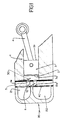
- the reciprocating hermetic compressor used in the present invention comprises a cylinder block 1, where is defined a cylinder 2, in which inside reciprocates a piston 3, driven by a connecting rod 4.
- the cylinder block 1 presents a pair of opposite faces, to which are opened the ends of the cylinder 2, a valve plate 10 and a cylinder head 20 being attached against one of said opposite faces of the cylinder 1, the cylinder head 20 forming together with said valve plate 10 two internal cavities, one of which defining a suction chamber 21 and the other defining a discharge chamber 22.
- the cylinder 2 maintains a selective fluid communication with said suction chamber 21 and discharge chamber 22, throuth respective gas suction and discharge orifices 11 and 12, provided on the valve plate 10, in which are mounted respective suction valve 30 and discharge valve 40, both of the reed type and actuating during the suction and discharge strokes of the operative cycle of the reciprocating piston 3.
- Each said valve when at the closed condition, presents a sealing portion seated on a corresponding valve seat 11a, 12a, defined at an adjacent portion of the respective orifice of the valve plate 10, the discharge valve 40 being mounted against a front face 10a of the valve plate 10 facing the inside of the discharge chamber 22.
- the opening of the discharge valve 40 is obtained when the pressure inside the cylinder 2, together with the force of the impelling means (if there is one), results in an opening force upstream said discharge valve 40, corresponding to the summing of the retarding forces acting on said discharge valve 40, in order to keep the latter seated on the respective valve seat 12a.
- the action of this opening force can only overcome the retarding forces at an instant of time posterior to the instant in which the pressure in the cylinder 2 reaches its discharge value.
- the compressors in which there is an impelling means to minimize this time difference present the inconvenience of having said impelling means in permanent activity, thereby impairing the closing of the discharge valve 40.
- retarding forces include inertia of movement of said discharge valve 40 and an effect of adhesion of the latter to the corresponding valve seat 12a, caused by the presence of an oil film between one portion of the lower face of the discharge valve 40 facing the valve plate 10 and said valve seat 12a of said discharge valve 40.
- the valve plate 10 presents, at its front face 10a, a lowered portion 13, which is provided adjacent to the discharge orifice 12 and which lodges therewithin a pneumatic valve impelling means 60, disposed in such a way as to actuate against the face of the discharge valve 40 facing the valve plate 10, in order to cause the opening of said discharge valve 40, at least at the final phase of the compression stroke, said actuation beginning after a certain time of the compression end has elapsed, as described below.
- the impelling means 60 defines, between the discharge chamber 22 and said lowered portion 13, a subchamber 70, adjacent to the discharge chamber 22 and separated therefrom by a movable blocking element or wall, in order to avoid any direct fluid communication with said discharge chamber 22 through the lowered portion 13.
- a constant fluid communication with the discharge chamber 22 occurs through an intermediate connecting volume 80, through which the compression gas flows before reaching the subchamber 70.
- said intermediate connecting volume 80 is defined by a discharge muffler chamber, provided in the cylinder block 1.
- the impelling means 60 presents an operative position, defined when the pressure in the discharge chamber 22 substantially equals the pressure in the subchamber 70, and an inoperative position, displaced towards the subchamber when the pressure in the discharge chamber 22 is higher than that of the subchamber 70, said impelling means being maintained constantly elastically in this condition, while there is a pressure differential between the discharge chamber 22 and the subchamber 70.
- the impelling means 60 keeps contact with the discharge valve 40 at least at one point of the latter.
- said contact is unique, the valve impelling means 60 being designed in such a way as to exert an opening force against the discharge valve 40, without causing torsions on the latter around is longitudinal axis.
- an intermediate volume 80 prevents the pressure variations in the discharge chamber 22 from being transmitted to the subchamber 70, thus avoiding to submit the impelling means 60, and consequently the discharge valve 40, to an opening force before the programmed opening instant, thereby impairing the adequate closing of the discharge valve 40.
- said intermediate volume 80 is constructed in such a way that the compression gas, propagating to the subchamber 70, reaches the latter within a time posterior to the closing of the discharge valve 40, without affecting said closing and in time to cause a new operative condition of the valve impelling means 60, before a new discharge pressure is reached in the cylinder 2.
- the operative condition of the valve impelling means 60 is associated with a condition of pressure balance between the subchamber 70 and the discharge chamber 22, established after a determined time interval for the closing of the discharge valve 40 has elapsed, said balance actuating in the impelling means 60 till the instant of a new opening of the discharge valve.
- the valve impelling means 60 comprises a separating element 61, such as a flexible pneumatic membrane, carrying a valve actuating means 62, said flexible membrane being mounted in the lowered portion 13, separating the subchamber 70 from the discharge chamber 22 and avoiding the fluid communication therebetween.
- a separating element 61 such as a flexible pneumatic membrane
- the subchamber 70 with a protecting stop, which acts against the impelling means 60, so as to limit the retracting displacement of the latter and, consequently, its bending, to a deformation at maximum slightly higher than that needed to obtain and maintain the spacing between the valve actuating means 62 and the discharge valve 40, upon the sudden pressure rise in the discharge chamber 22 during the opening of said discharge valve 40.
- the valve actuating means 62 is in the form of a pneumatic valve actuating means, projecting from the flexible membrane 61 and having a connecting end through which said valve actuating means 62 is attached to said flexible membrane 61, and an opposite free end, which is in contact with an adjacent portion of the discharge valve 40, when the latter is at its closed position and the valve actuating means 62 is at an operative condition, achieved by the pressure balance between the discharge chamber 22 and subchamber 70.
- the valve actuating means 62 remains temporarily forcing the discharge valve 40 to a partial opening condition, when said discharge valve 40 is not subjected to the retarding forces acting thereon and is maintained adhered to the respective valve seat 12a, till the opening of said valve.
- the communication between the discharge muffler chamber 80 and the discharge chamber 22 is made through a first gas conducting tube 81, which is opened to the inside of the discharge chamber 22, by means of a throughbore 23 provided in the body of the cylinder head 20, transversely to the wall adjacent to the discharge muffler chamber 80.
- the communication between the latter and the subchamber 70 is made through a second gas conducting tube 82, having one end mounted in the discharge muffler chamber 80 and an opposite end connected to a first end of a through channel 24, provided along a portion of the valve plate 10, the second end of said channel, opposite to the first end, being opened to the subchamber 70.
- the discharge valve 40 opens instantaneously, allowing the gas compressed inside the cylinder 2 to reach the discharge chamber 22, by passing through the discharge orifice 12. This opening is due to the action of the valve impelling means 60 on said discharge valve 40, liberating said valve from the action of the retarding forces and forcing it to the partial opening position, as described above.
- the opening of the discharge valve 40 generates a temporary pressure rise in the discharge chamber 22, causing a pressure unbalance between the latter and the subchamber 70.
- This pressure rise in the discharge chamber 22 forces the impelling means 60 to a retracting inoperative position, when said impelling means is separated from the adjacent portion of the discharge valve 40, said inoperative position lasting till the pressure in the subchamber 70 equals the pressure in the discharge chamber 22 and again causes the operative position of the valve actuating means 62.
- This separation may occur by the individual retraction of the flexible membrane 61, as well as of the valve actuating means 62, in case both are sensible to the pressure variations between the discharge chamber 22 and subchamber 70.
- the retracting condition of the impelling means 60 will last as much as the pressure unbalance between the discharge chamber 22 and subchamber 70. This unbalance lasts till after the closing condition of the discharge valve 40 is reached.
- the time to return to the balance condition and consequently, to the operative position of the valve actuating means 62, is calculated so that said condition be reached before a new condition of discharge pressure inside the cylinder.
- the return time to the pressure balance condition corresponds to the time the compressed gas takes to flow from the discharge chamber 22 to the subchamber 70, which means the time needed by said gas to pass through the intermediate volume 80 or, according to the preferred illustrated form, through the discharge muffler chamber 80.
- the balance condition may occur at any instant of time after the closing of the discharge valve 40.
- the balance condition is achieved at a time close to that in which a new condition of gas discharge pressure in the cylinder is reached, in order to avoid that possible oscilations that by chance were not attenuated in the intermediate volume be transmitted to the valve impelling means 60, leading the discharge valve 40 to an early inadequate partial opening condition.
- the valve actuating means 62 may also be in the form of a stiff element, such as an impelling needle, which maintains a selective contact with the adjacent sealing portion of the discharge valve 40.
- an impelling needle In the opening of the latter, the higher pressure in the discharge chamber 22 exerts a force on the flexible membrane 61, in the direction of retraction thereof relatively to the discharge valve 40. This force results in the retraction of said impelling needle, avoiding any contact with the discharge valve 40, even when the latter is in the closed condition.
- the impelling needle or stem is mounted to a flexible membrane, such as described above, attached to a receiving recess, provided on the internal wall of the cylinder head 20 and opposite to the valve plate 10, so that the free end of said impelling needle keeps contact with a portion of the upper face of the discharge valve 40, opposite to the sealing portion of the latter.
- the actuation of the discharge valve 40 is made by more than one impelling means mounted in subchambers 70.
- at least one of said subchambers 70 may be defined spaced from or adjacent to the cylinder head.
- These solutions further include the possibility of the subchambers 70 being hermetic, defining chambers of predetermined constant pressure. Either one of said constructions permits to achieve a valve opening at an instant of time closer to the instant in which the discharge pressure is reached inside the cylinder 2, without however affecting or even altering the closing of said discharge valve 40 during the operative cycle of the reciprocating piston 3.
- the above description refers to constructions directed only to the discharge valve of the hermetic compressor, said solutions may also be applied to the suction valve.
Landscapes
- Engineering & Computer Science (AREA)
- Mechanical Engineering (AREA)
- General Engineering & Computer Science (AREA)
- Compressor (AREA)
- Check Valves (AREA)
- Compressors, Vaccum Pumps And Other Relevant Systems (AREA)
Claims (9)
- Betätigungssystem für ein Auslaßventil eines hermetischen Verdichters, der Art mit einem Kolben (3), der innerhalb eines Zylinders (2) hin- und herläuft, einer Ventilplatte (10) zum Verschließen eines pumpseitigen Endes des Zylinders (2), und einem Zylinderkopf (20), der an der Ventilplatte (10) befestigt ist, um mit letzterer eine Auslaßöffnung (22) festzulegen, die über eine Auslaßkammer (12) in einer selektiven Strömungsverbindung mit dem Zylinder (2) gehalten wird, wobei die Auslaßöffnung (12) auf der Ventilplatte (10) vorgesehen ist und durch ein entsprechendes Platten-Auslaßventil (40) verschlossen wird,
gekennzeichnet durch:
wenigstens eine Nebenkammer (70), die mit der Auslaßkammer (22) in einer Strömungsverbindung steht, welche laufend durch ein bewegliches Absperrelement (60) blockiert ist, das zwischen einer Funktionsstellung, die festgelegt ist, wenn der Druck in der Auslaßkammer (22) und der in der Nebenkammer (70) im wesentlichen gleich ist, und einer unwirksamen Stellung bewegt wird, die zur Nebenkammer (70) hin versetzt ist und immer dann eingenommen wird, wenn der Druck innerhalb der Auslaßkammer (22) den Druck der Nebenkammer (70) übersteigt, und zwar um einen Wert, der ausreicht, um die Versetzung des Absperrelementes (60) von dessen Funktionsstellung zur unwirksamen Stellung zu bewirken, wobei das Absperrelement (60) laufend und elastisch in die Funktionsstellung gedrückt wird, in der es auf das Auslaßventil (40) eine Kraft ausübt, um letzteres von dessen geschlossener Lage in eine von der Auslaßöffnung (12) entfernte Lage zu bewegen. - Betätigungssystem für ein Auslaßventil nach Anspruch 1, dadurch gekennzeichnet, daß wenigstens eine Nebenkammer (70) der Auslaßkammer (22) benachbart liegt.
- Betätigungssystem für ein Auslaßventil nach Anspruch 2, dadurch gekennzeichnet, daß jede Nebenkammer (70) in einem entsprechenden, vertieften Abschnitt (13) an einer der Innenwände der Auslaßkammer (22) festgelegt wird.
- Betätigungssystem für ein Auslaßventil nach Anspruch 3, dadurch gekennzeichnet, daß der abgesenkte Abschnitt (13) auf der Ventilplatte (10) an einem Abschnitt derselben vorgesehen ist, welcher der Auslaßöffnung (12) benachbart ist.
- Betätigungssystem für ein Auslaßventil nach Anspruch 1, dadurch gekennzeichnet, daß das Absperrelement (60) mit dem Auslaßventil (40) zumindest an einem Punkt in Kontakt steht.
- Betätigungssystem für ein Auslaßventil nach Anspruch 1, dadurch gekennzeichnet, daß die Nebenkammer (70) über ein verbindendes Zwischenvolumen (80) in dauernder Strömungsverbindung mit der Auslaßkammer (22) steht, das so dimensioniert ist, daß es eine sofortige Druckübertragung von der Auslaßkammer (22) zu der Nebenkammer (70) verhindert.
- Betätigungssystem für ein Auslaßventil nach Anspruch 6, dadurch gekennzeichnet, daß das verbindende Zwischenvolumen (80) zumindest eine Auslaß-Schalldämpferkammer des Verdichters umfaßt, die in dauernder Strömungsverbindung mit der Auslaßkammer (22) und mit der Nebenkammer (70) steht.
- Betätigungssystem für ein Auslaßventil nach Anspruch, 6, dadurch gekennzeichnet, daß die Nebenkammer (70) in Strömungsverbindung mit dem verbindenden Zwischenvolumen (80) steht, und zwar über einen Durchgangskanal (24), der wenigstens an einer der Wände der Auslaßkammer (22) vorgesehen ist.
- Betätigungssystem für ein Auslaßventil nach Anspruch 8, dadurch gekennzeichnet, daß der Durchgangskanal (24) durch die Erstreckung der Ventilplatte (10) zwischen einem Ende derselben, das dem verbindenden Zwischenvolumen (80) benachbart ist, und der Nebenkammer (17) verläuft.
Applications Claiming Priority (3)
| Application Number | Priority Date | Filing Date | Title |
|---|---|---|---|
| BR9301059A BR9301059A (pt) | 1993-05-07 | 1993-05-07 | Sistema de acionamento de válvula de descarga para compressores herméticos |
| BR9301059 | 1993-05-07 | ||
| PCT/BR1994/000018 WO1994027047A1 (en) | 1993-05-07 | 1994-05-02 | Discharge valve actuating system for hermetic compressors |
Publications (2)
| Publication Number | Publication Date |
|---|---|
| EP0697067A1 EP0697067A1 (de) | 1996-02-21 |
| EP0697067B1 true EP0697067B1 (de) | 1996-12-04 |
Family
ID=4056118
Family Applications (1)
| Application Number | Title | Priority Date | Filing Date |
|---|---|---|---|
| EP19940913461 Expired - Lifetime EP0697067B1 (de) | 1993-05-07 | 1994-05-02 | Betätigungseinrichtung eines auslassventils für einen hermetischen verdichter |
Country Status (6)
| Country | Link |
|---|---|
| US (1) | US5678983A (de) |
| EP (1) | EP0697067B1 (de) |
| JP (1) | JP3188709B2 (de) |
| BR (1) | BR9301059A (de) |
| DE (1) | DE69401064T2 (de) |
| WO (1) | WO1994027047A1 (de) |
Families Citing this family (8)
| Publication number | Priority date | Publication date | Assignee | Title |
|---|---|---|---|---|
| BR9803517A (pt) * | 1998-04-13 | 2000-02-15 | Brasil Compressores Sa | Arranjo de descarga para compressor hermético. |
| JP5324841B2 (ja) * | 2008-06-27 | 2013-10-23 | サンデン株式会社 | 圧縮機の弁板装置 |
| JP5324893B2 (ja) * | 2008-11-18 | 2013-10-23 | サンデン株式会社 | 圧縮機の弁板装置 |
| CN102312820B (zh) * | 2011-08-17 | 2014-12-31 | 佛山市广顺电器有限公司 | 一种高效进排气簧片阀自定位密封结构 |
| CN102705223A (zh) * | 2012-05-09 | 2012-10-03 | 苏州百胜动力机器有限公司 | 一种液压泵 |
| US11105326B2 (en) * | 2016-05-07 | 2021-08-31 | Emerson Climate Technologies, Inc. | Single piece valve plate assembly for a reciprocating compressor |
| CN106704150B (zh) * | 2016-12-21 | 2018-07-27 | 广州万宝集团压缩机有限公司 | 一种多功能阀片及气阀系统 |
| AT17214U1 (de) * | 2019-12-19 | 2021-09-15 | Anhui meizhi compressor co ltd | Hermetisch gekapselter Kältemittelverdichter |
Family Cites Families (4)
| Publication number | Priority date | Publication date | Assignee | Title |
|---|---|---|---|---|
| DE3136948A1 (de) * | 1981-09-17 | 1983-03-31 | Wabco Westinghouse Fahrzeugbremsen GmbH, 3000 Hannover | Einrichtung zur erzeugung von druckgas |
| JPS6075782A (ja) * | 1983-09-30 | 1985-04-30 | Japan Steel Works Ltd:The | 往復動圧縮機の無段階容量調節装置 |
| BR9002967A (pt) * | 1990-06-19 | 1991-12-24 | Brasil Compressores Sa | Valvula para compressor hermetico de refrigeracao |
| JP5718064B2 (ja) | 2011-01-07 | 2015-05-13 | 花王株式会社 | 抗真菌剤 |
-
1993
- 1993-05-07 BR BR9301059A patent/BR9301059A/pt not_active IP Right Cessation
-
1994
- 1994-05-02 WO PCT/BR1994/000018 patent/WO1994027047A1/en not_active Ceased
- 1994-05-02 JP JP52474594A patent/JP3188709B2/ja not_active Expired - Fee Related
- 1994-05-02 EP EP19940913461 patent/EP0697067B1/de not_active Expired - Lifetime
- 1994-05-02 DE DE69401064T patent/DE69401064T2/de not_active Expired - Lifetime
- 1994-05-02 US US08/535,108 patent/US5678983A/en not_active Expired - Lifetime
Also Published As
| Publication number | Publication date |
|---|---|
| JPH08509794A (ja) | 1996-10-15 |
| DE69401064D1 (de) | 1997-01-16 |
| US5678983A (en) | 1997-10-21 |
| EP0697067A1 (de) | 1996-02-21 |
| JP3188709B2 (ja) | 2001-07-16 |
| DE69401064T2 (de) | 1997-10-09 |
| WO1994027047A1 (en) | 1994-11-24 |
| BR9301059A (pt) | 1994-11-29 |
Similar Documents
| Publication | Publication Date | Title |
|---|---|---|
| US5171137A (en) | Valve for a hermetic refrigeration compressor | |
| EP1446580B1 (de) | Saugschalldämpfer für einen hermetischen hubkolbenverdichter | |
| US5527160A (en) | Mechanical shift, pneumatic assist pilot valve | |
| EP0697067B1 (de) | Betätigungseinrichtung eines auslassventils für einen hermetischen verdichter | |
| EP0654606B1 (de) | Geräuschmindernder Ventilfänger | |
| JPH08200211A (ja) | 減アイシング空気弁 | |
| JPH086690B2 (ja) | 気密冷蔵コンプレッサ | |
| JPH10505396A (ja) | 自由ピストン機械用の一方向弁付き中心合わせシステム | |
| KR20050053740A (ko) | 소형의 밀폐형 압축기용 흡입 밸브 | |
| US5651267A (en) | Starting arrangement for small refrigeration systems | |
| EP1427940B1 (de) | Ventilvorrichtung für hermetischen kompressor | |
| WO1999053200A1 (en) | A discharge arrangement for a hermetic compressor | |
| JPS6488065A (en) | Refrigeration circuit with refrigerant flow control mechanism | |
| WO2002025111A1 (en) | Reciprocating compressor driven by a linear motor | |
| JPS635592B2 (de) | ||
| WO2007128713A1 (en) | A compressor | |
| EP0965754A3 (de) | Ventil zur Hubregelung zur Verwendung in einem Kompressor mit veränderlicher Verdrängung | |
| JPS63190579U (de) | ||
| KR19980028739A (ko) | 밀폐형 압축기 | |
| KR19990003388U (ko) | 밀폐형 압축기의 고효율 토출밸브 조립체 | |
| KR20020027793A (ko) | 압축기의 토출부 | |
| KR970045553A (ko) | 로타리 압축기의 토출장치 | |
| KR20030018849A (ko) | 스크롤 압축기의 소음 저감 구조 | |
| KR970027846A (ko) | 로타리 압축기의 베인구조 |
Legal Events
| Date | Code | Title | Description |
|---|---|---|---|
| PUAI | Public reference made under article 153(3) epc to a published international application that has entered the european phase |
Free format text: ORIGINAL CODE: 0009012 |
|
| 17P | Request for examination filed |
Effective date: 19951102 |
|
| AK | Designated contracting states |
Kind code of ref document: A1 Designated state(s): DE GB IT |
|
| GRAG | Despatch of communication of intention to grant |
Free format text: ORIGINAL CODE: EPIDOS AGRA |
|
| 17Q | First examination report despatched |
Effective date: 19960304 |
|
| GRAH | Despatch of communication of intention to grant a patent |
Free format text: ORIGINAL CODE: EPIDOS IGRA |
|
| GRAH | Despatch of communication of intention to grant a patent |
Free format text: ORIGINAL CODE: EPIDOS IGRA |
|
| GRAA | (expected) grant |
Free format text: ORIGINAL CODE: 0009210 |
|
| ITF | It: translation for a ep patent filed | ||
| AK | Designated contracting states |
Kind code of ref document: B1 Designated state(s): DE GB IT |
|
| REF | Corresponds to: |
Ref document number: 69401064 Country of ref document: DE Date of ref document: 19970116 |
|
| PLBE | No opposition filed within time limit |
Free format text: ORIGINAL CODE: 0009261 |
|
| STAA | Information on the status of an ep patent application or granted ep patent |
Free format text: STATUS: NO OPPOSITION FILED WITHIN TIME LIMIT |
|
| 26N | No opposition filed | ||
| REG | Reference to a national code |
Ref country code: GB Ref legal event code: IF02 |
|
| PGFP | Annual fee paid to national office [announced via postgrant information from national office to epo] |
Ref country code: GB Payment date: 20110505 Year of fee payment: 18 |
|
| PGFP | Annual fee paid to national office [announced via postgrant information from national office to epo] |
Ref country code: DE Payment date: 20110520 Year of fee payment: 18 Ref country code: IT Payment date: 20110520 Year of fee payment: 18 |
|
| GBPC | Gb: european patent ceased through non-payment of renewal fee |
Effective date: 20120502 |
|
| PG25 | Lapsed in a contracting state [announced via postgrant information from national office to epo] |
Ref country code: IT Free format text: LAPSE BECAUSE OF NON-PAYMENT OF DUE FEES Effective date: 20120502 |
|
| REG | Reference to a national code |
Ref country code: DE Ref legal event code: R119 Ref document number: 69401064 Country of ref document: DE Effective date: 20121201 |
|
| PG25 | Lapsed in a contracting state [announced via postgrant information from national office to epo] |
Ref country code: GB Free format text: LAPSE BECAUSE OF NON-PAYMENT OF DUE FEES Effective date: 20120502 |
|
| PG25 | Lapsed in a contracting state [announced via postgrant information from national office to epo] |
Ref country code: DE Free format text: LAPSE BECAUSE OF NON-PAYMENT OF DUE FEES Effective date: 20121201 |