EP0695687A2 - Device for strapping goods - Google Patents
Device for strapping goods Download PDFInfo
- Publication number
- EP0695687A2 EP0695687A2 EP95107013A EP95107013A EP0695687A2 EP 0695687 A2 EP0695687 A2 EP 0695687A2 EP 95107013 A EP95107013 A EP 95107013A EP 95107013 A EP95107013 A EP 95107013A EP 0695687 A2 EP0695687 A2 EP 0695687A2
- Authority
- EP
- European Patent Office
- Prior art keywords
- strapping
- roller
- rollers
- strapping means
- guide frame
- Prior art date
- Legal status (The legal status is an assumption and is not a legal conclusion. Google has not performed a legal analysis and makes no representation as to the accuracy of the status listed.)
- Granted
Links
Images


Classifications
-
- B—PERFORMING OPERATIONS; TRANSPORTING
- B65—CONVEYING; PACKING; STORING; HANDLING THIN OR FILAMENTARY MATERIAL
- B65B—MACHINES, APPARATUS OR DEVICES FOR, OR METHODS OF, PACKAGING ARTICLES OR MATERIALS; UNPACKING
- B65B13/00—Bundling articles
- B65B13/18—Details of, or auxiliary devices used in, bundling machines or bundling tools
Definitions
- the invention relates to a device for strapping packaged goods according to the preamble of claim 1.
- the strapping means in modern machines almost exclusively weldable, thermoplastic plastic band, is shot in by means of a conveying device by means of a conveying device by means of a conveying device, by means of a conveying device, surrounding the packaged goods provided on a packing table or roller conveyor.
- these conveying devices generally consisting of roller-shaped pairs of rollers with at least one driven roller, with the strapping means held between the rollers being advanced.
- strapping tool guide frames generally have four rounded corner areas, which, however, can also offer particular resistance to the leading strapping end, even if they are carefully manufactured.
- the length of the strapping guide frame into which the strapping agent is loaded is must be 12 meters and more. It can be seen from this that the strapping of strapping material into a strapping guide frame can be problematic and can lead to considerable malfunctions.
- An intermediate conveyor has therefore been arranged in addition to the conveyor device assigned to the strapping agent supply or the sealing assembly, at a position within the strapping device guide frame at which the strapping device transported by the conveyor device has covered approximately 2/3 of its total circulation path.
- the two rollers of this additional conveyor consist of rollers, the axes of which are aligned transversely to the orbit of the strapping means and one roller behind and the other roller in front of the strapping means acts on the latter.
- the strap' is synonymous with the side of the strap pointing to the outside of the strap guide frame.
- the roller arranged here can rotate about a stationary axis, while the roller engaging on the inside of the strapping guide frame on the strapping means is provided in such a way that it is attached to a pivotable arm which can be pivoted out so far by means of a lifting magnet that the strapping means , if it comes free from the strapping guide frame to be tightened against the packaged goods ready, cannot get caught on the lifted roller.
- the smaller diameter sections form an insertion gap for the entry of the strapping between the two rollers, while the roughened sections are used for transporting the strapping.
- the ventilated, opposite second roller is a plastic roller with a smooth, slightly compressible jacket.
- the design, in particular of the metallic roller, is very complex and leads to an inhomogeneous transport of the strapping means, which manifests itself in a disadvantageous 'picking'.
- thermoplastic plastic belts with flat rectangular ones Cross-section as strapping means the risk that the strapping is compressed in a wedge shape, which manifests itself in that coercive forces are exerted on the belt section advanced by the additional conveyor, which can lead to an arcuate course of the leading strapping.
- the invention has for its object to provide a device of the type outlined in the preamble of claim 1, in which the additional conveyor is designed considerably simpler.
- Another aspect of the invention relates to a simplified possibility for venting at least one roller of the additional conveyor roller pair. Furthermore, the forces exerted by the rollers of the additional conveyor on the strapping means should be as low as possible, but in no case should they lead to malfunctions.
- the invention solves the problem in connection with the features of the preamble of claim 1 by its characterizing features. Thereafter, it is provided that the axes of the rollers laterally next to the orbit penetrate the plane defined by this and the at least one ventable roller can be swung out of the strapping movement path to the side against the action of a spring loading it against the strapping means and thus against the second roller .
- the axes of the rollers of the pair of additional conveyor rollers also lie transversely, in particular perpendicularly, in the additional conveyor of the invention. to the orbit of the strapping tool.
- they are not, as in the prior art, in planes parallel to the orbit, but penetrate the plane defined by the orbit or the strapping means.
- ventilation of at least one roll need not be pivoted around a large angular path of up to 90 o the role in question, but only a very small distance. This is because the roller does not engage the strapping means in front of and behind the orbit, but rather affects the orbit on the long sides of the strapping means.
- the release of the roll can be left to the strapping pull in a very simplified manner, if the strapping tool is tightened as a result of reversing the drive of the conveyor from the Strapping guide frame is released to be tightly tightened around the package.
- the pair of rollers now acting on both narrow sides and not on the front and the back of the strapping means is no longer able to disadvantageously deform the strapping means.
- the very small-area attack of the rollers on the long sides of the strapping means is completely sufficient to push the strapping means securely forward, but on the other hand surprisingly low forces are required, which therefore do not force the strapping means to buckle.
- the device designated overall by 10 in FIG. 1 serves for strapping particularly compressible packaged goods 11 such as corrugated cardboard layers or the like.
- First of all comprises a supply of strapping means 12 arranged close to the ground with strapping means 14 wound on a drum 13, in particular thermally weldable plastic strap.
- a cross member 16 is arranged vertically movable in the direction of the double arrow 17.
- the cross member 16 forms a press plate for compressing the packaged goods 11 or is a component thereof and stores on its upper side only a roughly indicated, known strapping closure assembly 18, which is used to form a closure overlapping strapping ends of the later around the packaged goods 11 taut strapping is used.
- a strapping means storage 19 is assigned to the closure assembly 18 and, like the closure assembly 18, is driven and guided in a uniform movement and thus in synchronism with the press plate 16.
- Both the posts 15, 15 'and the cross member 16 are assigned strapping guides 20 to 23 in the form of straight channels or channel sections of a known type. It is also known to form the portal-like strapping guide channel structure 20 to 23 into a self-contained strapping guide frame in that a lance or a bayonet 24 underneath the packaged goods 11 or the pallet on which it is stored, on the bottom contains a straight strapping guide channel.
- a strapping device infeed device 25 is provided directly behind the strapping stock 13, which, by means of strapping conveyor rollers 26, at least one of which is mechanically driven and the other is positively coupled to the strapping device feed, denotes the strapping device 14 into a strapping guide 28 Advance, which is arranged next to the post-like strapping guide 21 and parallel to it (behind it in the drawing).
- a strapping device 29 is arranged to be vertically movable, which has the task of transferring the strapping device 14 at the point at which the strapping device deflection 29 is located to a horizontally arranged strapping device transfer line 30, which it is used for Closure unit 18 continues. In the exemplary embodiment, this happens through the strapping material store 19. As soon as the leading free strapping end has reached a desired position in the closure assembly 18, the starting position for a first strapping of a packaged product 11 is reached.
- the packaged goods 11 to be strapped have been conveyed into the strapping zone perpendicular to the drawing plane.
- the strapping means 14 is again by means of a two conveyor rollers and the closure unit 18 assigned conveyor 32, namely counterclockwise with respect to FIG. 1 through the strapping guides 20, 21, 24, 22, and 23 and through the strapping means 33 to 36 located between them in the strapping path until the front end of the strapping means 14 again in the closure unit 18.
- the pressing plate 16, the closure assembly 18 and the belt store 19 lower down onto the top of the packaged goods 11, which is now compressed to a large extent depending on the nature and requirements.
- the drive of the strapping conveyor rollers 32 is reversed so that they pull back the strapping means 14 brought in by the strapping stock 12, while the other end of the strapping means is held on the closure assembly 18 by means of a clamp. Due to the strapping means retraction, the strapping means 14 is pulled out from the inside of all the strapping means guides which are designed for this purpose in a known manner, for example thus have flexible lips or flaps which open against spring action.
- the strapping guide frame 31 formed from the strapping guides 20-23 and the strapping deflections 33-36 represents a very long orbit for the strapping.
- the known additional conveyor 37 has two rollers 38' and 39 'designed as rollers.
- the rotatable roller 38 ' which is held in a fixed position, is assigned to the outside of the strapping guide frame 31 and by means of its not shown Motors can be driven in rotation.
- the second roller 39 ′ engages on the opposite side of the strapping means 14 and is consequently assigned to the inside of the strapping means guide frame 31.
- the axes 40 'and 41' of the two rollers 38 'and 39' are parallel to one another and parallel to the orbit defined by the longitudinal advance of the strapping means 14, namely on the one hand in front of and on the other hand behind the orbit. So that the strapping means 14 can be drawn in from its loading position within the strapping means guide frame 31 onto the circumference of the package, it is necessary to ventilate the roller 39 ′ which is arranged towards the inside of the guide frame.
- This ventable roller 39 ' is therefore mounted on a swivel arm 42 which can be swiveled out of the position according to FIG. 10 into the position according to FIG. 11 by means of a lifting magnet 43, which is indicated by the arrow denoted by 44.
- the roller 39 ' must be pivoted out so far that it is practically no longer in overlap with the roller 38' so that the strapping means 14 can snap towards the packaged goods 11 unhindered.
- the control of the solenoid 43 ' must be clocked depending on the machine cycle. Since, on the other hand, in the position shown in FIG. 10, the pair of rollers 38 '/ 39' must also be able to grasp the incoming end of the strapping means 24 in the nip, the particularly complex measures explained above on the roller 38 'were necessary.
- the strip shown, which is flat in cross section, is contacted as strapping means 14 not by its broad sides, but rather by the narrow longitudinal edges 14 'of the rollers 38 and 39, which here are not designed as wide rollers but as flat, disc-shaped wheels are.
- the arrangement is such that the roller 38 is rotatably driven by a motor 45 and that on the end of the axle 40 remote from the roller 38, a pinion 46 is rotatably mounted, which meshes with a pinion 47, which at the associated end of the axis 41 sits, the other end of which carries the second roller 39.
- two receptacles 48 and 49 are used, each around an axis 50 and 51 parallel to the plane of the drawing and thus parallel to the longitudinal direction of the strapping means 14 or to the orbit of the strapping means 14 in the direction of the arrows 52 in FIG. 4 and 53 are pivotable.
- the arrangement of the pivot axes 50 and 51 is deliberately made close to the gears 46 and 47 so that they are always, ie also in the case of the pivoted apart Position according to Fig. 4 do not lose their meshing engagement.
- the two rollers 38 and 39 are tensioned against one another by means of a spring 54.
- the spring 54 is designed as a tension spring and its spring force can be adjusted via adjusting spindles 55 that can be reached from opposite sides.
- the roller gap is limited by stops 56 which can be set independently of one another and which are likewise designed as screw spindles and are supported on a central receptacle 57 which is connected to a machine-fixed console which is not shown in FIGS. 2 and 4 but is indicated in FIG. 1 by 58 .
- the free ends of the adjustable stop spindles 56 serve as stops for the central webs of the holders 48 and 49, as can be seen from FIG. 2 and also from FIG. 4. Since each receptacle 48 and 49 is assigned its own adjusting spindle 56, a lateral adjustment of the roller gap can be carried out, i.e. the rollers 38 and 39 can be aligned in their exact transverse position to the strapping means 14.
- the construction is additionally carried out so that by means of a lever mechanism 59, not shown in detail, the pivoting out, for example, of the roller 38 in the direction of arrow 52 inevitably leads to the second roller 39 being pivoted out accordingly in the direction of arrow 53, even if no force directly affects them themselves.
- rollers 38 and 39 which frictionally drive the strapping means 14 on its longitudinal edges are, as clearly illustrated in FIGS. 2 and 4, concave, in particular V-shaped arrows. This ensures an exact centering of the strapping means 14 in the roller gap and on the other hand also favors the outward movement of the rollers 38 and 39 (arrows 52 and 53) when the strapping means 14 is pulled off in the direction of the arrow 60. This situation is shown schematically in FIG. 4, and FIG. 5 shows the associated view.
- FIGS. 6 to 9 differs from the first described distinguishes that additionally folding strapping retaining plates 61 and 62 are provided, which also cover the strapping guide channel 31 in the area of the additional conveyor 37 to the inside of the frame 31.
- the essential difference from the first embodiment is that when the strapping means 14 is pulled off in the direction of the arrow 60, the strapping means 14 peels out of the flaps, opening the flaps.
- Both embodiments described have the same mode of operation in common.
- the lifting of at least one roller 38 or 39, in the exemplary embodiment the synchronous ventilation of both rollers 38 and 39 at the same time, is done either directly by accessing the strapping means 14 on the peripheral surfaces of the rollers 38 and 39 (FIGS. 2 to 5) or indirectly by the fact that Strapping means 14 directly engages the flaps 61, which in turn move the rollers 38 and 39 to the release position.
Abstract
Description
Die Erfindung betrifft eine Vorrichtung zum Umreifen von Packgut nach dem Oberbegriff des Anspruchs 1.The invention relates to a device for strapping packaged goods according to the preamble of claim 1.
Bei Umreifungsmaschinen derjenigen Art, von denen die Erfindung ausgeht, wird das Umreifungsmittel, bei modernen Maschinen nahezu ausschließlich verschweißbares, thermoplastisches Kunststoffband, mittels einer Fördereinrichtung durch den das auf einem Packtisch oder Rollengang bereitgestellte Packgut umrundenden Führungsrahmen mittels einer Fördereinrichtung eingeschossen. Dies geschieht, je nach Maschinentyp, entweder nahe dem Umreifungsmittel-Vorrat oder im Bereich des Umreifungsmittel-Verschlußaggregats, wobei diese Fördereinrichtungen in der Regel aus walzenförmigen Rollenpaaren mit mindestens einer angetriebenen Rolle bestehen, wobei das zwischen den Rollen gefaßte Umreifungsmittel vorgeschoben wird. Mit zunehmender Umreifungsmittel-Förderung nimmt der freie, geschobene Umreifungsmittelabschnitt an Länge stetig zu, und die Sicherheit des Umreifungsmittelumlaufs innerhalb des Umreifungsmittel-Führungsrahmens ist entsprechend zunehmend von der Qualität des Bandes, insbesondere von dessen Knicksteifigkeit abhängig. Andererseits weisen Umreifungsmittel-Führungsrahmen in der Regel vier zwar abgerundete Eckbereiche auf, die jedoch auch bei sorgfältiger Fertigung dem voreilenden Umreifungsmittelende einen besonderen Widerstand entgegensetzen können. Bei großen Maschinen, so insbesondere bei sogenannten 'Verpackungspressen' beträgt die Länge des Umreifungsmittel-Führungsrahmens, in den das Umreifungsmittel geladen werden muß, 12 Meter und mehr. Hieraus wird ersichtlich, daß das Einschießen von Umreifungsmittel in einen Umreifungsmittel-Führungsrahmen durchaus problematisch sein und zu erheblichen Betriebsstörungen führen kann.In strapping machines of the type from which the invention is based, the strapping means, in modern machines almost exclusively weldable, thermoplastic plastic band, is shot in by means of a conveying device by means of a conveying device by means of a conveying device, by means of a conveying device, surrounding the packaged goods provided on a packing table or roller conveyor. Depending on the type of machine, this is done either near the strapping stock or in the area of the strapping closure unit, these conveying devices generally consisting of roller-shaped pairs of rollers with at least one driven roller, with the strapping means held between the rollers being advanced. As the amount of strapping is increased, the free, pushed strapping section increases in length and the security of the strapping circulation within the strapping guide frame is correspondingly increasingly dependent on the quality of the strap, in particular on its buckling stiffness. On the other hand, strapping tool guide frames generally have four rounded corner areas, which, however, can also offer particular resistance to the leading strapping end, even if they are carefully manufactured. In the case of large machines, particularly in the case of so-called 'packaging presses', the length of the strapping guide frame into which the strapping agent is loaded is must be 12 meters and more. It can be seen from this that the strapping of strapping material into a strapping guide frame can be problematic and can lead to considerable malfunctions.
Man hat deshalb zusätzlich zu der dem Umreifungsmittel-Vorrat bzw. dem Verschlußaggregat zugeordneten Fördereinrichtung noch einen Zwischenförderer angeordnet, und zwar an einer Position innerhalb des Umreifungsmittel-Führungsrahmens, an der das mit der Fördereinrichtung transportierte Umreifungsmittel etwa 2/3 seines gesamten Umlaufweges zurückgelegt hat.An intermediate conveyor has therefore been arranged in addition to the conveyor device assigned to the strapping agent supply or the sealing assembly, at a position within the strapping device guide frame at which the strapping device transported by the conveyor device has covered approximately 2/3 of its total circulation path.
Bei einer durch offenkundige Vorbenutzung bekannten Umreifungsvorrichtung bestehen die beiden Rollen dieses Zusatzförderers aus Walzen, deren Achsen quer zur Umlaufbahn des Umreifungsmittels ausgerichtet sind und wobei eine Rolle hinter und die andere Rolle vor dem Umreifungsmittel an diesem angreift. 'Hinter dem Umreifungsmittel' ist gleichbedeutend mit der zur Außenseite des Umreifungsmittel-Führungsrahmens weisenden Seite des Umreifungsmittels. Die hier angeordnete Walze kann um eine stationäre Achse drehen, während die auf der Innenseite des Umreifungsmittel-Führungsrahmens am Umreifungsmittel angreifende Rolle dadurch lüftbar vorgesehen ist, daß sie an einem schwenkbaren Arm angebracht ist, der mittels eines Hubmagneten derart weit ausschwenkbar ist, daß das Umreifungsmittel, wenn es vom Umreifungsmittel-Führungsrahmen freikommt, um gegen das bereit gehaltene Packgut gestrafft zu werden, nicht an der gelüfteten Walze hängen bleiben kann.In a strapping device known from public prior use, the two rollers of this additional conveyor consist of rollers, the axes of which are aligned transversely to the orbit of the strapping means and one roller behind and the other roller in front of the strapping means acts on the latter. 'Behind the strap' is synonymous with the side of the strap pointing to the outside of the strap guide frame. The roller arranged here can rotate about a stationary axis, while the roller engaging on the inside of the strapping guide frame on the strapping means is provided in such a way that it is attached to a pivotable arm which can be pivoted out so far by means of a lifting magnet that the strapping means , if it comes free from the strapping guide frame to be tightened against the packaged goods ready, cannot get caught on the lifted roller.
Diese Steuerung der lüftbaren Rolle des Zusatzförderers mittels eines Hubmagneten und dessen erforderlicher Ansteuerung ist natürlich aufwendig. Problematisch ist es außerdem, das durch die (erste) Fördereinrichtung dem Zusatzförderer zugeführte Umreifungsmittel zwischen die beiden Walzen des Walzenpaares des Zusatzförderers zu bringen, ohne daß das vorlaufende Ende sich im Walzenspalt verfängt. Andererseits wird natürlich gefordert, daß die Walzen des Zusatzförderers das ankommende Umreifungsmittelende zuverlässig greifen können. Um diese einander widersprüchlichen Zielsetzungen zu beherrschen, ist bei dem vorbekannten Zusatzförderer die stationär drehende Rolle in aufwendiger Weise mit in Umfangsrichtung ihres Mantels abwechselnd glatten, im Durchmesser kleineren und geriffelten, im Durchmesser größeren Teilabschnitten versehen. Die im Durchmesser kleineren Abschnitte bilden einen Einführspalt zum Eintreten des Umreifungsmittels zwischen die beiden Walzen, während die aufgerauhten Abschnitte dem Umreifungsmittel-Transport dienen. Die lüftbare, gegenüberliegende zweite Walze ist eine Kunststoffwalze mit glattem, leicht kompressiblem Mantel. Die Ausgestaltung insbesondere der metallischen Walze ist sehr aufwendig und führt zu einem inhomogen Transport des Umreifungsmittels, welches sich in einem nachteiligen 'Rupfen' äußert.This control of the ventable role of the additional conveyor by means of a lifting magnet and its required control is of course complex. It is also problematic to bring the strapping means supplied to the additional conveyor by the (first) conveyor device between the two rollers of the pair of rollers of the additional conveyor without the leading end getting caught in the nip. On the other hand, it is of course required that the rollers of the additional conveyor can reliably grip the incoming strapping end. In order to master these contradictory objectives, in the previously known additional conveyor, the stationary rotating roller is provided in a complex manner with sections which are alternately smooth in the circumferential direction of their jacket, smaller in diameter and corrugated, larger in diameter. The smaller diameter sections form an insertion gap for the entry of the strapping between the two rollers, while the roughened sections are used for transporting the strapping. The ventilated, opposite second roller is a plastic roller with a smooth, slightly compressible jacket. The design, in particular of the metallic roller, is very complex and leads to an inhomogeneous transport of the strapping means, which manifests itself in a disadvantageous 'picking'.
Stehen die Achsen der beiden Walzen des Rollenpaares des Zusatzförderers nicht exakt parallel zueinander, besteht darüber hinaus noch bei Verwendung der üblichen thermoplastischen Kunststoffbänder mit flachrechteckigem Querschnitt als Umreifungsmittel die Gefahr, daß das Umreifungsmittel keilförmig komprimiert wird, was sich dahingehend äußert, daß auf das vom Zusatzförderer vorgeschobene Bandabschnitt Zwangskräfte ausgeübt werden, die zu einem bogenförmigen Verlauf des voreilenden Umreifungsmittels führen können.If the axes of the two rollers of the pair of rollers of the additional conveyor are not exactly parallel to one another, there is also still use of the usual thermoplastic plastic belts with flat rectangular ones Cross-section as strapping means the risk that the strapping is compressed in a wedge shape, which manifests itself in that coercive forces are exerted on the belt section advanced by the additional conveyor, which can lead to an arcuate course of the leading strapping.
Hiervon ausgehend, liegt der Erfindung die Aufgabe zugrunde, eine Vorrichtung der im Oberbegriff des Anspruches 1 näher umrissenen Art bereitzustellen, bei der der Zusatzförderer erhebliche einfacher ausgestaltet ist. Ein weiterer Aspekt der Erfindung betrifft eine vereinfachte Möglichkeit zum Lüften mindestens einer Rolle des Zusatzförder-Rollenpaares. Des weiteren sollen die von den Rollen des Zusatzförderers auf das Umreifungsmittel ausgeübten Kräfte möglichst gering sein, in keinem Falle aber zu Betriebsstörungen führen können.Proceeding from this, the invention has for its object to provide a device of the type outlined in the preamble of claim 1, in which the additional conveyor is designed considerably simpler. Another aspect of the invention relates to a simplified possibility for venting at least one roller of the additional conveyor roller pair. Furthermore, the forces exerted by the rollers of the additional conveyor on the strapping means should be as low as possible, but in no case should they lead to malfunctions.
Die Erfindung löst Aufgabe in Verbindung mit den Merkmalen des Oberbegriffs des Patentanspruchs 1 durch dessen kennzeichnenden Merkmale. Danach ist vorgesehen, daß die Achsen der Rollen seitlich neben der Umlaufbahn die von dieser definierte Ebene durchdringen und die wenigstens eine lüftbare Rolle gegen Wirkung einer diese gegen das Umreifungsmittel und somit dieses gegen die zweite Rolle belastenden Feder aus der Umreifungsmittel-Bewegungsbahn zur Seite ausschwenkbar ist.The invention solves the problem in connection with the features of the preamble of claim 1 by its characterizing features. Thereafter, it is provided that the axes of the rollers laterally next to the orbit penetrate the plane defined by this and the at least one ventable roller can be swung out of the strapping movement path to the side against the action of a spring loading it against the strapping means and thus against the second roller .
Wie beim Stand der Technik liegen auch beim Zusatzförderer der Erfindung die Achsen der Rollen des Zusatzförderer-Rollenpaares quer, insbesondere lotrecht, zur Umlaufbahn des Umreifungsmittels. Sie liegen jedoch nicht, wie beim Stand der Technik, in zur Umlaufbahn parallelen Ebenen, sondern durchdringen die von der Umlaufbahn bzw. dem Umreifungsmittel definierte Ebene. Daraus resultiert, daß im Falle des Lüftens mindestens einer Rolle die betreffende Rolle nicht um einen großen Winkelweg von bis zu 90o verschwenkt zu werden braucht, sondern lediglich um eine nur sehr geringe Wegstrecke. Dies rührt daher, daß die Rolle nicht vor und hinter der Umlaufbahn am Umreifungsmittel angreifen, sondern die Umlaufbahn an den Umreifungsmittel-Längsseiten tangieren. Ist es aber nicht erforderlich, die lüftbare Rolle weit zu verschwenken, kann man nach der Erkenntnis der Erfindung das Lüften der Rolle auf sehr vereinfachte Weise allein dem Umreifungsmittel-Zug überlassen, wenn das Umreifungsmittel durch das übliche Straffen infolge Reversierung des Antriebs der Fördereinrichtung von den Umreifungsmittel-Führungsrahmen freikommt, um eng um das Packstück herumgestrafft zu werden. Das nunmehr zu beiden Schmalseiten und nicht an der Vorderseite und der Rückseite des Umreifungsmittels angreifende Rollenpaar ist nicht mehr in der Lage, das Umreifungsmittel nachteilig zu verformen. Zudem hat sich überraschend gezeigt, daß der sehr kleinflächige Angriff der Rollen an den Längsseiten des Umreifungsmittels völlig ausreicht, das Umreifungsmittel sicher vorzuschieben, andererseits dazu aber erstaunlich geringe Kräfte erforderlich sind, die deshalb dem Umreifungsmittel keine Knickung aufzwingen.As in the prior art, the axes of the rollers of the pair of additional conveyor rollers also lie transversely, in particular perpendicularly, in the additional conveyor of the invention. to the orbit of the strapping tool. However, they are not, as in the prior art, in planes parallel to the orbit, but penetrate the plane defined by the orbit or the strapping means. As a result, in the case of ventilation of at least one roll need not be pivoted around a large angular path of up to 90 o the role in question, but only a very small distance. This is because the roller does not engage the strapping means in front of and behind the orbit, but rather affects the orbit on the long sides of the strapping means. However, if it is not necessary to pivot the ventable roll far, according to the knowledge of the invention, the release of the roll can be left to the strapping pull in a very simplified manner, if the strapping tool is tightened as a result of reversing the drive of the conveyor from the Strapping guide frame is released to be tightly tightened around the package. The pair of rollers now acting on both narrow sides and not on the front and the back of the strapping means is no longer able to disadvantageously deform the strapping means. In addition, it has surprisingly been found that the very small-area attack of the rollers on the long sides of the strapping means is completely sufficient to push the strapping means securely forward, but on the other hand surprisingly low forces are required, which therefore do not force the strapping means to buckle.
Weitere Ausgestaltungen der Erfindung sowie zweckmäßige und vorteilhafte Merkmale sind in den Unteransprüchen angegeben und ergeben sich auch aus der nachfolgenden Beschreibung der Erfindung anhand eines Ausführungsbeispiels unter Bezugnahme auf die Zeichnungen. Darin zeigen:
- Fig. 1
- eine schematische Ansicht einer als 'Verpackungspresse' ausgestatteten Umreifungsmaschine,
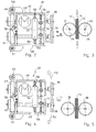
- Fig. 2
- die wesentlichen Teile eines Zusatzförderers entsprechend der Erfindung in der Umreifungsmittel-Förderphase,
- Fig. 3
- eine Stirnansicht in Richtung des Ansichtspfeiles III der Fig. 2,
- Fig. 4
- eine der Fig. 2 entsprechende Darstellung, wobei nun die Rollen des Zusatzförderers zur Freigabe des Umreifungsmittels gelüftet sind,
- Fig. 5
- eine der Fig. 3 entsprechende Stirnansicht auf Fig. 4,
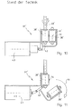
- Fig. 6 bis 9
- im wesentlichen den Fig. 2 bis 5 entsprechende Darstellung, wobei im Bereich des Zusatzförderers zusätzliche, das Umreifungsmittel während des Förderns rückhaltende Klappen vorgesehen sind, und
- Fig. 10 und 11
- Darstellungen zur Erläuterung des Standes der Technik.
- Fig. 1
- 1 shows a schematic view of a strapping machine equipped as a 'packaging press',
- Fig. 2
- the essential parts of an additional conveyor according to the invention in the strapping conveying phase,
- Fig. 3
- 3 shows an end view in the direction of the arrow III of FIG. 2,
- Fig. 4
- 2 shows a representation corresponding to FIG. 2, the rollers of the additional conveyor now being released to release the strapping means,
- Fig. 5
- 3 shows an end view corresponding to FIG. 4 on FIG. 4,
- 6 to 9
- 2 to 5 essentially corresponding representation, wherein additional flaps are provided in the region of the additional conveyor, retaining the strapping means during conveying, and
- 10 and 11
- Representations to explain the prior art.
Die in Fig. 1 insgesamt mit 10 bezeichnete Vorrichtung dient zum Umreifen von insbesondere kompressiblem Packgut 11 wie Wellpappelagen o.dgl. umfaßt zunächst einen bodennah angeordneten Umreifungsmittelvorrat 12 mit auf einer Trommel 13 aufgewickeltem Umreifungsmittel 14, insbesondere thermisch verschweißbarem Kunststoffband.The device designated overall by 10 in FIG. 1 serves for strapping particularly compressible packaged
An Pfosten 15, 15' ist ein Querträger 16 in Richtung des Doppelpfeils 17 vertikal verfahrbar angeordnet. Der Querträger 16 bildet eine Pressplatte zum Komprimieren des Packguts 11 aus bzw. ist deren Bestandteil und lagert auf seiner Oberseite ein nur grob angedeutetes, an sich bekanntes Umreifungsmittel-Verschlußaggregat 18, welches der Ausbildung eines Verschlusses einander überlappender Umreifungsmittel-Enden des später um das Packgut 11 gestrafften Umreifungsmittels dient. Dem Verschlußaggregat 18 ist ein Umreifungsmittelspeicher 19 zugeordnet, der wie das Verschlußaggregat 18 bewegungseinheitlich und somit synchron mit der Pressplatte 16 angetrieben und geführt ist.On
Sowohl den Pfosten 15, 15' als auch dem Querträger 16 sind Umreifungsmittelführungen 20 bis 23 in Gestalt von geraden Kanälen bzw. Kanalabschnitten bekannter Bauart zugeordnet. Ebenfalls bekannt ist es, das portalartige Umreifungsmittelführungskanalgebilde 20 bis 23 dadurch zu einem in sich geschlossenen Umreifungsmittel-Führungsrahmen auszubilden, daß bodenseitig eine das Packgut 11 oder die Palette, auf dem es lagert, unterfahrende Lanze bzw. ein Bajonett 24, das ebenfalls einen geradlinigen Umreifungsmittelführungskanal enthält.Both the
Damit das Umreifungsmittel 14 um das Packgut 11 geführt werden kann, muß es zunächst einmal dem Verschlußaggregat 18 zugeführt werden. Hierzu ist eine Umreifungsmittel-Einschußvorrichtung 25 unmittelbar hinter dem Umreifungsmittelvorrat 13 vorgesehen, die mittels Umreifungsmittel-Förderrollen 26, von denen wenigstens eine maschinell angetrieben und die andere mit dieser zwangsgekuppelt ist, an der mit 27 bezeichneten Umreifungsmittel-Einspeisung das Umreifungsmittel 14 in eine Umreifungsmittelführung 28 vorschieben, die neben der pfostenartigen Umreifungsmittelführung 21 und zu ihr Parallel (bezüglich der Zeichnung hinter ihr) angeordnet ist. An dieser Umreifungsmittelführung 28 ist eine Umreifungsmittel-Umlenkung 29 vertikalbeweglich angeordnet, die die Aufgabe hat, das Umreifungsmittel 14 jeweils an der Stelle, an der sich die Umreifungsmittel-Umlenkung 29 befindet, an eine horizontal angeordnete Umreifungsmittel-Überleitung 30 zu übergeben, die es zum Verschlußaggregat 18 weiterführt. Beim Ausführungsbeispiel geschieht dies durch den Umreifungsmittelspeicher 19 hindurch. Sobald das führende freie Umreifungsmittelende eine Sollposition im Verschlußaggregat 18 erreicht hat, ist die Ausgangsstellung für eine erste Umreifung eines Packguts 11 erreicht.So that the strapping means 14 can be guided around the packaged
Senkrecht zur Zeichenebene ist das zu umreifende Packgut 11 in die Umreifungszone gefördert worden. Das Umreifungsmittel 14 wird mittels einer wiederum zwei Förderrollen aufweisenden sowie dem Verschlußaggregat 18 zugeordneten Fördereinrichtung 32 vorgeschoben, und zwar bezüglich Fig. 1 entgegen dem Uhrzeigersinn durch die Umreifungsmittelführungen 20, 21, 24, 22, und 23 sowie durch die jeweils dazwischen in der Umreifungsmittel-Bahn befindlichen Umreifungsmittel-Umlenkungen 33 bis 36, bis das vordere Ende des Umreifungsmittels 14 wieder in das Verschlußaggregat 18 gelangt.The packaged
Schon während dieses Herumführens des Umreifungsmittel oder sofort danach, senken sich Pressplatte 16, Verschlußaggregat 18 und Bandspeicher 19 nach unten auf die Oberseite des Packguts 11, welches nun je nach Beschaffenheit und Anforderung entsprechend stark komprimiert wird. Um sodann das Umreifungsmittel 14 um das komprimierte Packgut 11 zu straffen, wird der Antrieb der Umreifungsmittel-Förderrollen 32 reversiert, so daß diese das vom Umreifungsmittelvorrat 12 herangeführte Umreifungsmittel 14 zurückziehen, während das andere Umreifungsmittelende mittels einer Klemme am Verschlußaggregat 18 festgehalten wird. Aufgrund des Umreifungsmittelrückzugs wird das Umreifungsmittel 14 innen aus sämtlichen Umreifungsmittelführungen herausgezogen, die dazu in bekannter Weise ausgebildet sind, beispielsweise also flexible Lippen oder gegen Federwirkung öffnende Klappen aufweisen.Already during this guiding of the strapping means or immediately thereafter, the
Aus vorstehender Beschreibung ist ersichtlich, daß der aus den Umreifungsmittelführungen 20-23 sowie den Umreifungsmittel-Umlenkungen 33-36 ausgebildete Umreifungsmittel-Führungsrahmen 31 eine sehr lange Umlaufbahn für das Umreifungsmittel darstellt.From the above description it can be seen that the strapping
Es ist daher verständlich, daß Schwierigkeiten in der Umreifungsmittelzuführung auftreten können, wenn man es ausschließlich der Fördereinrichtung 32 überläßt, das Umreifungsmittel in einer das Packgut 11 umrundenden Art und Weise durch den Umreifungsmittel-Führungsrahmen 31 zu schießen. Aus diesem Grunde ist es bereits bekannt, zusätzlich zu der Fördereinrichtung 33 einen mit 37 bezeichneten Zusatzförderer dem Umreifungsmittel-Führungsrahmen 31 zuzuordnen bzw. in die Umlaufbahn des Umreifungsmittels 14 zu integrieren. Dabei hat es sich als vorteilhaft erwiesen, den Zusatzförderer 37 an einer Stelle des Umreifungsmittel-Führungsrahmens 31 anzuordnen, an der das von der Fördereinrichtung 32 transportierte Umreifungsmittel 14 etwa 2/3 seiner Wegstrecke für eine vollständige Umreifungsmittel-Führungsrahmen-Füllung zurückgelegt hat. Folgerichtig ist daher bei dem in Fig. 1 dargestellten Ausführungsbeispiel der Zusatzförderer 37 hinter der dritten Umreifungsmittel-Umlenkung 35 im Bereich des zweiten vertikalen Rahmenabschnitts 22 vorgesehen.It is therefore understandable that difficulties in the strapping supply can occur if it is left solely to the
Bevor die wesentlichen Bauelemente und Eigenschaften des Zusatzförderers 37 anhand der Fig. 2 bis 5 einerseits und der Fig. 6 bis 9 andererseits näher beschrieben und dargestellt werden, soll zunächst ein Blick auf den Stand der Technik geworfen werden, wie er in den Fig. 10 und 11 schematisch gezeigt ist. Als wesentliche Bauelemente weist der bekannte Zusatzförderer 37' zwei als Walzen ausgebildete Rollen 38' und 39' auf. Die raumfest gehaltene drehbare Rolle 38' ist dabei der Außenseite des Umreifungsmittel-Führungsrahmens 31 zugeordnet und mittels seines nicht dargestellten Motors rotierend antreibbar. Auf der gegenüberliegenden Seite des Umreifungsmittels 14 greift die zweite Walze 39' an, die folglich der Innenseite des Umreifungsmittel-Führungsrahmens 31 zugeordnet ist. In Förderposition liegen die Achsen 40' und 41' der beiden Walzen 38' und 39' zueinander parallel sowie parallel zu der durch den Längsvorschub des Umreifungsmittels 14 definierten Umlaufbahn, und zwar einerseits vor und andererseits hinter der Umlaufbahn. Damit das Umreifungsmittel 14 von seiner Ladeposition innerhalb des Umreifungsmittels-Führungsrahmens 31 auf den Umfang des Packstücks eingezogen werden kann, ist es erforderlich, die zum Führungsrahmen-Innern weisend angeordnete Walze 39' zu lüften. Diese lüftbare Rolle 39' ist deshalb an einem Schwenkarm 42 gelagert, der mittels eines Hubmagneten 43 von der Position nach Fig. 10 in die Position nach Fig. 11 ausschwenkbar ist, was der mit 44 bezeichnete Pfeil andeutet. Wie ersichtlich, muß die Rolle 39' so weit ausgeschwenkt werden, daß sie praktisch nicht mehr in Überdeckung zur Rolle 38' steht, damit das Umreifungsmittel 14 ungehindert zum Packgut 11 hinschnellen kann. Die Steuerung des Hubmagneten 43' muß in Abhängigkeit vom Maschinenarbeitszyklus getaktet werden. Da andererseits in der Stellung entsprechend Fig. 10 das Walzenpaar 38'/39' auch in der Lage sein muß, das ankommende Ende des Umreifungsmittels 24 im Walzenspalt fassen zu können, sind die eingangs erläuterten besonders aufwendigen Maßnahmen an der Walze 38' erforderlich gewesen.Before the essential components and properties of the
Entsprechend Fig. 2, anhand der ein erstes Ausführungsbeispiel der Erfindung erläutert wird, weist der Zusatzförderer 37 - zunächst in Übereinstimmung mit dem Stand der Technik - wiederum zwei Rollen 38 und 39 zur Förderung des Umreifungsmittels 14 auf, doch sind deren Achsen nicht vor und hinter der durch die Bewegung des Umreifungsmittels 14 definierten Umlaufbahn angeordnet, sondern zu den beiden Seiten der Umlaufbahn, und die Achsen 40 und 41 sind nicht parallel zur Umlaufbahn orientiert, sondern durchsetzen diese im wesentlichen lotrecht. Die Folge davon ist, daß das dargestellte, im Querschnitt flachrechteckige Band als Umreifungsmittel 14 nicht mit seinen Breitseiten, sondern mit den schmalen Längskanten 14' von den Rollen 38 und 39 kontaktiert wird, die hier nicht als breite Walzen, sondern als flache scheibenförmige Räder ausgebildet sind.2, on the basis of which a first exemplary embodiment of the invention is explained, the Additional conveyor 37 - initially in accordance with the prior art - again two
Im einzelnen ist die Anordnung so getroffen, daß die Rolle 38 von einem Motor 45 drehantreibbar ist und daß auf dem der Rolle 38 entfernten Ende der Achse 40 ein Zahnritzel 46 drehfest angebracht ist, das mit einem Zahnritzel 47 kämmt, welches am zugeordneten Ende der Achse 41 sitzt, deren anderes Ende die zweite Rolle 39 trägt.In detail, the arrangement is such that the
Zur Halterung der beschriebenen Teile dienen zwei Aufnahmen 48 und 49, die jeweils um eine zur Zeichenebene senkrecht und somit zur Längsrichtung des Umreifungsmittels 14 bzw. zur Umlaufbahn des Umreifungsmittels 14 parallele Achse 50 bzw. 51 in Richtung der in Fig. 4 der gestellten Pfeile 52 und 53 schwenkbar sind. Die Anordnung der Schwenkachsen 50 und 51 ist bewußt nahe an den Zahnrädern 46 und 47 vorgenommen, damit diese stets, d.h. auch im Falle der auseinandergeschwenkten Position nach Fig. 4 ihren kämmenden Eingriff nicht verlieren.To hold the parts described, two
Die beiden Rollen 38 und 39 sind mittels einer Feder 54 kraftschlüssig gegeneinander gespannt. Die Feder 54 ist als Zugfeder ausgebildet und über von gegenüberliegenden Seiten erreichbaren Stellspindeln 55 in ihrer Federkraft einstellbar.The two
Der Walzenspalt wird begrenzt durch unabhängig voneinander einstellbare Anschläge 56, die ebenfalls als Schraubspindeln ausgebildet sind und an einer zentralen Aufnahme 57 lagern, die mit einer in den Fig. 2 und 4 nicht dargestellten, in Fig. 1 jedoch mit 58 angedeuteten maschinenfesten Konsole verbunden ist. Die freien Enden der verstellbaren Anschlagspindeln 56 dienen als Anschläge für die Zentralstege der Halter 48 und 49, wie aus Fig. 2 und auch aus Fig. 4 ersichtlich ist. Da jeder Aufnahme 48 und 49 eine eigene Stellspindel 56 zugeordnet ist, kann eine Seitenjustierung des Walzenspaltes vorgenommen werden, d.h. die Rollen 38 und 39 können in ihrer exakten Querlage zum Umreifungsmittel 14 ausgerichtet werden.The roller gap is limited by
Im übrigen ist die Konstruktion ergänzend noch so ausgeführt, daß mittels einer nicht im einzelnen dargestellten Hebelmechanik 59 das Ausschwenken z.B. der Rolle 38 in Richtung des Pfeiles 52 zwangsweise dazu führt, daß die zweite Rolle 39 entsprechend in Richtung des Pfeiles 53 ausgeschwenkt wird, auch wenn auf diese selbst keine diesbezügliche Kraft unmittelbar einwirkt.In addition, the construction is additionally carried out so that by means of a
Die das Umreifungsmittel 14 an dessen Längskanten reibschlüssig antreibenden Umfangsflächen der Rollen 38 und 39 sind, wie es die Fig. 2 und 4 deutlich veranschaulichen, konkav ausgebildet, insbesondere V-förmig gepfeilt. Dadurch wird eine exakte Zentrierung des Umreifungsmittels 14 im Rollenspalt gewährleistet und andererseits auch das Ausweichen der Rollen 38 und 39 nach außen (Pfeile 52 und 53) begünstigt, wenn das Umreifungsmittel 14 in Richtung des Pfeiles 60 abgezogen wird. Diese Situation ist schematisch in Fig. 4 dargestellt, und Fig. 5 gibt die zugehörige Ansicht wieder.The circumferential surfaces of the
Während beim Ausführungsbeispiel entsprechend den Fig. 2 und 5 das Lüften der Rollen 38 und 39 durch Zug am Umreifungsmittel 14 in Richtung des Pfeiles 16 unmittelbar erfolgt, ist in den Fig. 6 bis 9 noch eine weitere Ausführungsform dargestellt, die sich von der erstbeschriebenen dadurch unterscheidet, daß zusätzlich klappbare Umreifungsmittel-Rückhaltebleche 61 bzw. 62 vorhanden sind, die den Umreifungsmittel-Führungskanal 31 auch im Bereich des Zusatzförderers 37 zur Innenseite des Rahmens 31 abdecken. Der wesentliche Unterschied zur ersten Ausführungsform besteht darin, daß im Falle des Abzugs des Umreifungsmittels 14 in Richtung des Pfeiles 60 das Umreifungsmittel 14 sich aus den Klappen herausschält, wobei es die Klappen öffnet. Da die Klappen 61 und 62 bewegungseinheitlich mit den Rollen 38 und 39 verbunden sind, indem sie beim Ausführungsbeispiel ebenfalls an den Haltern 48 und 49 angebracht sind, führt dies dazu, daß die Rollen 38 und 39 bereits gelüftet sind, wenn das sich aus den Klappen 61 herausschälende Umreifungsmittel 14 die Position der Rollen 38 und 39 erreicht. Erst dann, wenn das Umreifungsmittel 14 auch aus dem Bereich der Klappen 62 herausgezogen ist, gehen die Rollen 38 und 39 von ihrer Freigabeposition (Fig. 8 und 9) wieder in die Position entsprechend den Fig. 6 und 7 zurück, in der sie ein neu ankommendes Umreifungsmittel 14 fassen und fördern können.While in the embodiment according to FIGS. 2 and 5, the release of the
Beiden beschriebenen Ausführungsformen ist dieselbe Wirkungsweise gemeinsam. Das Lüften mindestens einer Rolle 38 oder 39, beim Ausführungsbeispiel das synchrone Lüften beider Rollen 38 und 39 zugleich, geschieht entweder unmittelbar durch Zugangriff des Umreifungsmittels 14 an den Umfangsflächen der Rollen 38 und 39 (Fig. 2 bis 5) oder mittelbar dadurch, daß das Umreifungsmittel 14 unmittelbar an den Klappen 61 öffnend angreift, die ihrerseits die Rollen 38 und 39 in Lüftstellung überführen.Both embodiments described have the same mode of operation in common. The lifting of at least one
Wie insbesondere aus einem Vergleich der Fig. 3 mit der Fig. 5 (bzw. der Fig. 7 mit der Fig. 9) hervorgeht, sind zur Freigabe des Umreifungsmittels 14 nur sehr geringe Verschwenkwege erforderlich. Die vom Band 14 ausgeübte Kraft, die notwendig ist, um aus dem Antrieb des Zusatzförderers 37 freizukommen, wird im wesentlichen durch die einstellbare Kraft der Feder 54 bestimmt. Diese Kraft ist in jedem Falle so groß, daß ein zuverlässiges, reibschlüssiges Fördern des Umreifungsmittels 14 durch die Rollen 38 und 39 möglich ist, andererseits so niedrig, daß die Pressung 38 und 39 an den schmalen Längskanten 14' des Umreifungsmittels 14 nicht ausreicht, um nachteilige Längsknickungen oder - wellungen des insbesondere bandförmigen Umreifungsmittels hervorzurufen.As can be seen in particular from a comparison of FIG. 3 with FIG. 5 (or FIG. 7 with FIG. 9), only very small pivoting paths are required to release the strapping
Soweit die Beschreibung der Erfindung anhand eines vorzugsweise im Querschnitt flachrechteckigen Bandes beschrieben worden ist, versteht es sich nach nunmehr umfassender Kenntnis der Erfindung und ihrer Eigenschaften von selbst, daß auch schnurförmiges Umreifungsmittel ohne weiteres mit Hilfe des Zusatzförderers 37 verwendet werden könnte. Auch dann unterscheidet sich die Erfindung in der beschriebenen vorteilhaften Weise vom Stand der Technik entsprechend den Fig. 10 und 11.Insofar as the description of the invention has been described with reference to a band which is preferably rectangular in cross section, it now goes without saying, after extensive knowledge of the invention and its properties, that cord-shaped strapping means could also be easily used with the aid of the
Claims (9)
Applications Claiming Priority (2)
| Application Number | Priority Date | Filing Date | Title |
|---|---|---|---|
| DE4420912A DE4420912A1 (en) | 1994-06-16 | 1994-06-16 | Device for strapping packaged goods |
| DE4420912 | 1994-06-16 |
Publications (3)
| Publication Number | Publication Date |
|---|---|
| EP0695687A2 true EP0695687A2 (en) | 1996-02-07 |
| EP0695687A3 EP0695687A3 (en) | 1996-03-13 |
| EP0695687B1 EP0695687B1 (en) | 1998-12-30 |
Family
ID=6520646
Family Applications (1)
| Application Number | Title | Priority Date | Filing Date |
|---|---|---|---|
| EP95107013A Expired - Lifetime EP0695687B1 (en) | 1994-06-16 | 1995-05-09 | Device for strapping goods |
Country Status (2)
| Country | Link |
|---|---|
| EP (1) | EP0695687B1 (en) |
| DE (2) | DE4420912A1 (en) |
Cited By (2)
| Publication number | Priority date | Publication date | Assignee | Title |
|---|---|---|---|---|
| US5809873A (en) * | 1996-11-18 | 1998-09-22 | Ovalstrapping, Inc. | Strapping machine having primary and secondary tensioning units and a control system therefor |
| US6415712B1 (en) | 1999-12-02 | 2002-07-09 | Enterprises International, Inc. | Track mechansim for guiding flexible straps around bundles of objects |
Families Citing this family (1)
| Publication number | Priority date | Publication date | Assignee | Title |
|---|---|---|---|---|
| DE19536964A1 (en) * | 1995-10-04 | 1997-04-10 | Smb Schwede Maschinenbau Gmbh | Belt drive device for hoop banding machine |
Citations (2)
| Publication number | Priority date | Publication date | Assignee | Title |
|---|---|---|---|---|
| DE1586954A1 (en) * | 1967-04-08 | 1970-10-29 | Titan Verpackungssysteme Gmbh | Method and device for strapping expandable goods, such as pressed bales |
| DE2640050A1 (en) * | 1976-05-19 | 1977-12-01 | Shinroku Mae | TAPE WRAPPING DEVICE ON A PACKAGING MACHINE |
Family Cites Families (1)
| Publication number | Priority date | Publication date | Assignee | Title |
|---|---|---|---|---|
| JPS5833046Y2 (en) * | 1980-08-19 | 1983-07-23 | 丸善工業株式会社 | Band insertion device for semi-automatic band packing machine |
-
1994
- 1994-06-16 DE DE4420912A patent/DE4420912A1/en not_active Withdrawn
-
1995
- 1995-05-09 EP EP95107013A patent/EP0695687B1/en not_active Expired - Lifetime
- 1995-05-09 DE DE59504670T patent/DE59504670D1/en not_active Expired - Lifetime
Patent Citations (2)
| Publication number | Priority date | Publication date | Assignee | Title |
|---|---|---|---|---|
| DE1586954A1 (en) * | 1967-04-08 | 1970-10-29 | Titan Verpackungssysteme Gmbh | Method and device for strapping expandable goods, such as pressed bales |
| DE2640050A1 (en) * | 1976-05-19 | 1977-12-01 | Shinroku Mae | TAPE WRAPPING DEVICE ON A PACKAGING MACHINE |
Cited By (5)
| Publication number | Priority date | Publication date | Assignee | Title |
|---|---|---|---|---|
| US5809873A (en) * | 1996-11-18 | 1998-09-22 | Ovalstrapping, Inc. | Strapping machine having primary and secondary tensioning units and a control system therefor |
| US6038967A (en) * | 1996-11-18 | 2000-03-21 | Ovalstrapping, Inc. | Strapping machine having primary and secondary tensioning units and a control system therefor |
| US6415712B1 (en) | 1999-12-02 | 2002-07-09 | Enterprises International, Inc. | Track mechansim for guiding flexible straps around bundles of objects |
| US6640700B2 (en) | 1999-12-02 | 2003-11-04 | Enterprises International, Inc. | Apparatus for applying flexible straps around bundles of objects |
| US6782679B2 (en) | 1999-12-02 | 2004-08-31 | Enterprises International, Inc. | Control mechanism for a feed and tension unit in a strapping apparatus |
Also Published As
| Publication number | Publication date |
|---|---|
| DE59504670D1 (en) | 1999-02-11 |
| EP0695687B1 (en) | 1998-12-30 |
| DE4420912A1 (en) | 1995-12-21 |
| EP0695687A3 (en) | 1996-03-13 |
Similar Documents
| Publication | Publication Date | Title |
|---|---|---|
| DE4100276C2 (en) | Strapping machine | |
| DE3119657C2 (en) | Method and machine for the production of packaging units | |
| EP1829807B1 (en) | Device for depositing strip material | |
| EP0498962B1 (en) | Method and means for realising a wound bobbin | |
| DE19549664C2 (en) | Device for packaging a roll of material web | |
| DE2151548C3 (en) | Card transport device | |
| DE3004470A1 (en) | DEVICE FOR WRAPPING LARGE PAPER ROLLS OR THE LIKE. | |
| EP1512630B1 (en) | Device for bundling articles, in particular compressible articles such as layers of corrugated cardboard | |
| DE10357829A1 (en) | Apparatus for longitudinally gripping a package, in particular a stack of newspapers, magazines or the like. | |
| DE3619939C2 (en) | Method and device for the intermediate storage of printed products resulting in scale formation | |
| EP0481323B1 (en) | Method for feeding a production machine with a precision centering and apparatus therefor | |
| EP0681958B1 (en) | Device for strapping especially compressible goods such as sheets of corrugated cardboard or the like | |
| EP0695687A2 (en) | Device for strapping goods | |
| DE10146460A1 (en) | Device for tensioning and closing strapping | |
| EP2657150B1 (en) | Strapping arrangement for palletised barrels or piece goods similar to barrels | |
| EP1072515B1 (en) | Device for unrolling a band in a tying machine | |
| EP1275582B1 (en) | Apparatus for wrapping a stack of products in a stretchable foil cover | |
| EP3867172A1 (en) | Device for transporting standing containers between clamping belts | |
| DE4206330A1 (en) | Device for wrapping parcels of newspapers - has foil passing from drum below delivery belts to one above plus cutter and heat sealer | |
| EP0703145B1 (en) | Feeding device for a binding means in a package binding machine | |
| DE3024626A1 (en) | STRAPPING DEVICE | |
| DE19854680A1 (en) | Packaging machine ribbon feed arrangement | |
| DE19920724C1 (en) | Deflection unit for the plastics ribbon at a wrapping machine has various positions for the ribbon entry and outlet channels according to requirements with a flexible guide at the inner deflection roller | |
| EP0826616A1 (en) | Band guiding device | |
| DE19824044A1 (en) | Tubular bag machine for packing objects in film |
Legal Events
| Date | Code | Title | Description |
|---|---|---|---|
| PUAI | Public reference made under article 153(3) epc to a published international application that has entered the european phase |
Free format text: ORIGINAL CODE: 0009012 |
|
| PUAL | Search report despatched |
Free format text: ORIGINAL CODE: 0009013 |
|
| AK | Designated contracting states |
Kind code of ref document: A2 Designated state(s): CH DE FR GB IT LI |
|
| AK | Designated contracting states |
Kind code of ref document: A3 Designated state(s): AT BE CH DE DK ES FR GB GR IE IT LI LU NL PT SE |
|
| 17P | Request for examination filed |
Effective date: 19960718 |
|
| 17Q | First examination report despatched |
Effective date: 19970605 |
|
| GRAG | Despatch of communication of intention to grant |
Free format text: ORIGINAL CODE: EPIDOS AGRA |
|
| GRAG | Despatch of communication of intention to grant |
Free format text: ORIGINAL CODE: EPIDOS AGRA |
|
| GRAH | Despatch of communication of intention to grant a patent |
Free format text: ORIGINAL CODE: EPIDOS IGRA |
|
| RBV | Designated contracting states (corrected) |
Designated state(s): CH DE FR GB IT LI |
|
| GRAH | Despatch of communication of intention to grant a patent |
Free format text: ORIGINAL CODE: EPIDOS IGRA |
|
| GRAA | (expected) grant |
Free format text: ORIGINAL CODE: 0009210 |
|
| AK | Designated contracting states |
Kind code of ref document: B1 Designated state(s): CH DE FR GB IT LI |
|
| REG | Reference to a national code |
Ref country code: CH Ref legal event code: NV Representative=s name: E. BLUM & CO. PATENTANWAELTE Ref country code: CH Ref legal event code: EP |
|
| GBT | Gb: translation of ep patent filed (gb section 77(6)(a)/1977) |
Effective date: 19981231 |
|
| REF | Corresponds to: |
Ref document number: 59504670 Country of ref document: DE Date of ref document: 19990211 |
|
| ET | Fr: translation filed | ||
| ITF | It: translation for a ep patent filed |
Owner name: STUDIO TORTA S.R.L. |
|
| PLBE | No opposition filed within time limit |
Free format text: ORIGINAL CODE: 0009261 |
|
| STAA | Information on the status of an ep patent application or granted ep patent |
Free format text: STATUS: NO OPPOSITION FILED WITHIN TIME LIMIT |
|
| 26N | No opposition filed | ||
| REG | Reference to a national code |
Ref country code: GB Ref legal event code: IF02 |
|
| PGFP | Annual fee paid to national office [announced via postgrant information from national office to epo] |
Ref country code: GB Payment date: 20040505 Year of fee payment: 10 |
|
| PGFP | Annual fee paid to national office [announced via postgrant information from national office to epo] |
Ref country code: FR Payment date: 20040519 Year of fee payment: 10 |
|
| PG25 | Lapsed in a contracting state [announced via postgrant information from national office to epo] |
Ref country code: GB Free format text: LAPSE BECAUSE OF NON-PAYMENT OF DUE FEES Effective date: 20050509 |
|
| GBPC | Gb: european patent ceased through non-payment of renewal fee |
Effective date: 20050509 |
|
| PG25 | Lapsed in a contracting state [announced via postgrant information from national office to epo] |
Ref country code: FR Free format text: LAPSE BECAUSE OF NON-PAYMENT OF DUE FEES Effective date: 20060131 |
|
| REG | Reference to a national code |
Ref country code: FR Ref legal event code: ST Effective date: 20060131 |
|
| REG | Reference to a national code |
Ref country code: CH Ref legal event code: PFA Owner name: SIGNODE BERNPAK GMBH Free format text: SIGNODE BERNPAK GMBH#MAGNUSSTRASSE 18#D-46535 DINSLAKEN (DE) -TRANSFER TO- SIGNODE BERNPAK GMBH#MAGNUSSTRASSE 18#D-46535 DINSLAKEN (DE) |
|
| REG | Reference to a national code |
Ref country code: CH Ref legal event code: PFA Owner name: ITW PACKAGING SYSTEMS GROUP GMBH, DE Free format text: FORMER OWNER: SIGNODE BERNPAK GMBH, DE |
|
| REG | Reference to a national code |
Ref country code: DE Ref legal event code: R082 Ref document number: 59504670 Country of ref document: DE Representative=s name: ROCHE, VON WESTERNHAGEN & EHRESMANN, DE |
|
| REG | Reference to a national code |
Ref country code: DE Ref legal event code: R082 Ref document number: 59504670 Country of ref document: DE Representative=s name: ROCHE, VON WESTERNHAGEN & EHRESMANN, DE Effective date: 20140120 Ref country code: DE Ref legal event code: R081 Ref document number: 59504670 Country of ref document: DE Owner name: SPG PACKAGING SYSTEMS GMBH, DE Free format text: FORMER OWNER: SIGNODE BERNPAK GMBH, 46535 DINSLAKEN, DE Effective date: 20140120 Ref country code: DE Ref legal event code: R081 Ref document number: 59504670 Country of ref document: DE Owner name: ITW PACKAGING SYSTEMS GROUP GMBH, DE Free format text: FORMER OWNER: SIGNODE BERNPAK GMBH, 46535 DINSLAKEN, DE Effective date: 20140120 |
|
| PGFP | Annual fee paid to national office [announced via postgrant information from national office to epo] |
Ref country code: DE Payment date: 20140529 Year of fee payment: 20 Ref country code: IT Payment date: 20140526 Year of fee payment: 20 Ref country code: CH Payment date: 20140527 Year of fee payment: 20 |
|
| REG | Reference to a national code |
Ref country code: CH Ref legal event code: PFA Owner name: SPG PACKAGING SYSTEMS GMBH, DE Free format text: FORMER OWNER: ITW PACKAGING SYSTEMS GROUP GMBH, DE |
|
| REG | Reference to a national code |
Ref country code: DE Ref legal event code: R082 Ref document number: 59504670 Country of ref document: DE Representative=s name: ROCHE, VON WESTERNHAGEN & EHRESMANN, DE |
|
| REG | Reference to a national code |
Ref country code: DE Ref legal event code: R082 Ref document number: 59504670 Country of ref document: DE Representative=s name: ROCHE, VON WESTERNHAGEN & EHRESMANN, DE Effective date: 20140922 Ref country code: DE Ref legal event code: R081 Ref document number: 59504670 Country of ref document: DE Owner name: SPG PACKAGING SYSTEMS GMBH, DE Free format text: FORMER OWNER: ITW PACKAGING SYSTEMS GROUP GMBH, 46535 DINSLAKEN, DE Effective date: 20140922 |
|
| REG | Reference to a national code |
Ref country code: DE Ref legal event code: R071 Ref document number: 59504670 Country of ref document: DE |
|
| REG | Reference to a national code |
Ref country code: DE Ref legal event code: R071 Ref document number: 59504670 Country of ref document: DE |
|
| REG | Reference to a national code |
Ref country code: CH Ref legal event code: PL |