EP0695656B1 - Rear axle for a motor vehicle - Google Patents
Rear axle for a motor vehicle Download PDFInfo
- Publication number
- EP0695656B1 EP0695656B1 EP95109758A EP95109758A EP0695656B1 EP 0695656 B1 EP0695656 B1 EP 0695656B1 EP 95109758 A EP95109758 A EP 95109758A EP 95109758 A EP95109758 A EP 95109758A EP 0695656 B1 EP0695656 B1 EP 0695656B1
- Authority
- EP
- European Patent Office
- Prior art keywords
- wheel
- suspension link
- supporting strut
- distance
- trailing arm
- Prior art date
- Legal status (The legal status is an assumption and is not a legal conclusion. Google has not performed a legal analysis and makes no representation as to the accuracy of the status listed.)
- Expired - Lifetime
Links
- 239000000725 suspension Substances 0.000 claims description 16
- 230000007935 neutral effect Effects 0.000 description 4
- 238000004519 manufacturing process Methods 0.000 description 3
- 238000010276 construction Methods 0.000 description 2
- 238000003466 welding Methods 0.000 description 2
- 238000005266 casting Methods 0.000 description 1
- 238000010586 diagram Methods 0.000 description 1
Images
Classifications
-
- B—PERFORMING OPERATIONS; TRANSPORTING
- B60—VEHICLES IN GENERAL
- B60G—VEHICLE SUSPENSION ARRANGEMENTS
- B60G7/00—Pivoted suspension arms; Accessories thereof
- B60G7/001—Suspension arms, e.g. constructional features
-
- B—PERFORMING OPERATIONS; TRANSPORTING
- B60—VEHICLES IN GENERAL
- B60G—VEHICLE SUSPENSION ARRANGEMENTS
- B60G21/00—Interconnection systems for two or more resiliently-suspended wheels, e.g. for stabilising a vehicle body with respect to acceleration, deceleration or centrifugal forces
- B60G21/02—Interconnection systems for two or more resiliently-suspended wheels, e.g. for stabilising a vehicle body with respect to acceleration, deceleration or centrifugal forces permanently interconnected
- B60G21/04—Interconnection systems for two or more resiliently-suspended wheels, e.g. for stabilising a vehicle body with respect to acceleration, deceleration or centrifugal forces permanently interconnected mechanically
- B60G21/05—Interconnection systems for two or more resiliently-suspended wheels, e.g. for stabilising a vehicle body with respect to acceleration, deceleration or centrifugal forces permanently interconnected mechanically between wheels on the same axle but on different sides of the vehicle, i.e. the left and right wheel suspensions being interconnected
- B60G21/051—Trailing arm twist beam axles
-
- B—PERFORMING OPERATIONS; TRANSPORTING
- B60—VEHICLES IN GENERAL
- B60G—VEHICLE SUSPENSION ARRANGEMENTS
- B60G2200/00—Indexing codes relating to suspension types
- B60G2200/10—Independent suspensions
- B60G2200/13—Independent suspensions with longitudinal arms only
- B60G2200/132—Independent suspensions with longitudinal arms only with a single trailing arm
- B60G2200/1324—Independent suspensions with longitudinal arms only with a single trailing arm with a resilient trailing arm
-
- B—PERFORMING OPERATIONS; TRANSPORTING
- B60—VEHICLES IN GENERAL
- B60G—VEHICLE SUSPENSION ARRANGEMENTS
- B60G2200/00—Indexing codes relating to suspension types
- B60G2200/20—Semi-rigid axle suspensions
- B60G2200/21—Trailing arms connected by a torsional beam, i.e. twist-beam axles
-
- B—PERFORMING OPERATIONS; TRANSPORTING
- B60—VEHICLES IN GENERAL
- B60G—VEHICLE SUSPENSION ARRANGEMENTS
- B60G2200/00—Indexing codes relating to suspension types
- B60G2200/40—Indexing codes relating to the wheels in the suspensions
- B60G2200/462—Toe-in/out
-
- B—PERFORMING OPERATIONS; TRANSPORTING
- B60—VEHICLES IN GENERAL
- B60G—VEHICLE SUSPENSION ARRANGEMENTS
- B60G2206/00—Indexing codes related to the manufacturing of suspensions: constructional features, the materials used, procedures or tools
- B60G2206/01—Constructional features of suspension elements, e.g. arms, dampers, springs
- B60G2206/10—Constructional features of arms
- B60G2206/124—Constructional features of arms the arm having triangular or Y-shape, e.g. wishbone
-
- B—PERFORMING OPERATIONS; TRANSPORTING
- B60—VEHICLES IN GENERAL
- B60G—VEHICLE SUSPENSION ARRANGEMENTS
- B60G2206/00—Indexing codes related to the manufacturing of suspensions: constructional features, the materials used, procedures or tools
- B60G2206/01—Constructional features of suspension elements, e.g. arms, dampers, springs
- B60G2206/20—Constructional features of semi-rigid axles, e.g. twist beam type axles
Definitions
- the invention relates to a rear axle for a motor vehicle according to the preamble of claim 1.
- a torsion beam rear axle known, the two trailing arms via a torsion switch Cross strut are interconnected.
- a support strut is provided by lateral forces, each in the area near the wheel on a support pin formed on the trailing arm and at their other end the two trailing arms together connecting cross strut is articulated.
- the distance of the The wheel-near end of the support strut to the trailing arm longitudinal axis is there is smaller than the distance of the articulation point on the cross strut to the trailing arm longitudinal axis.
- a disadvantage of this rear axle is that the support strut with the trailing arm and with the cross strut must be articulated.
- An articulated connection the support strut both on the cross strut and on Trailing arm however, with an increased construction, manufacturing and Assembly effort connected.
- From DE-OS 30 01 530 is a semi-trailing arm rear axle known, which consists of a rigidly connected to an axle beam Inclined link and a longitudinal strut designed as a spring leaf is formed with one end with the axle beam and is rigidly connected at its other end to the semi-trailing arm.
- the axle carrier itself is inelastic with the bearing Structure connected.
- the design of the longitudinal strut as a spring leaf has the consequence that under the influence of lateral forces there is an elongation the longitudinal strut comes, which means that the wheel is very strong in Toe-out is a strong oversteering self-steering behavior this results. It also stands by the Semi-trailing arm design a limited space between the available on both wheels.
- the invention has for its object a rear axle described in the preamble of claim 1 create which under the influence of a lateral force a neutral or understeering Has self-steering behavior, but still simple built and is therefore easy to manufacture and assemble and with which additional space between the two trailing arms can be won.
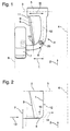
- Figure 1 shows a plan view of a trailing arm 1 of a rear axle of a motor vehicle, which extends counter to the forward direction (the forward direction of the vehicle is shown by the arrow 2) and rotatable about an axis 3 running normal (perpendicular) to the longitudinal plane 4 of the vehicle on Vehicle body is articulated (trailing link bearing 5).
- the forward direction of the vehicle is shown by the arrow 2
- the axis 3 running normal (perpendicular) to the longitudinal plane 4 of the vehicle on Vehicle body is articulated (trailing link bearing 5).
- only one trailing arm 1 is shown of the rear axle, specifically the trailing arm arranged to the left of the vehicle longitudinal median plane 4 in the forward direction.
- the trailing arm 1 is curved on the side facing away from the trailing arm bearing 5 in the direction of the outside of the vehicle 6, a wheel 7 being mounted on its end facing away from the trailing arm bearing 5.
- a support device 20 is formed on the trailing arm 1 for a suspension spring (helical spring) which is not resilient in the drawing for the sake of clarity.
- the suspension of the vehicle can also be done by means of torsion bars instead of by means of coil springs.
- the trailing arm 1 is widened in the direction of the outside of the vehicle 6.
- a support strut 9 is provided, which is rigidly connected to the trailing arm 1 at one end 10 in the curved region near the wheel and at its other end 11 in the region of the widened trailing arm bearing 5.
- the distance between the support strut 9 and the trailing arm longitudinal axis 12 in the area near the wheel (I) is lower than in the area of the trailing link bearing 5 (II).
- Trailing arm 1 and support strut 9 form in this embodiment a component that is made by casting. Another Manufacturing process is also conceivable, with the support strut 9 with the trailing arm 1 also e.g. connected by welding can be.
Landscapes
- Engineering & Computer Science (AREA)
- Mechanical Engineering (AREA)
- Vehicle Body Suspensions (AREA)
- Axle Suspensions And Sidecars For Cycles (AREA)
Description
Die Erfindung betrifft eine Hinterachse für ein Kraftfahrzeug
gemäß Oberbegriff des Patentanspruches 1.The invention relates to a rear axle for a motor vehicle
according to the preamble of
Aus der gattungsbildenden DE-OS 38 28 828 ist eine Verbundlenker-Hinterachse bekannt, deren beiden Längslenker über eine torsionsweiche Querstrebe miteinander verbunden sind. Zu Abstützung von Seitenkräften ist eine Stützstrebe vorgesehen, die jeweils im radnahen Bereich an einem am Längslenker angeformten Tragzapfen und an ihrem anderen Ende an der die beiden Längslenker miteinander verbindenden Querstrebe angelenkt ist. Der Abstand des radnahen Endes der Stützstrebe zur Längslenkerlängsachse ist dabei kleiner ist als der Abstand des Anlenkpunktes an der Querstrebe zu der Längslenkerlängsachse. Nachteilig bei dieser Hinterachse ist, daß die Stützstrebe mit dem Längslenker und mit der Querstrebe gelenkig verbunden sein muß. Eine gelenkige Anbindung der Stützstrebe sowohl an der Querstrebe als auch am Längslenker ist jedoch mit einem erhöhten Bau-, Fertigungs- und Montageaufwand verbunden.From the generic DE-OS 38 28 828 is a torsion beam rear axle known, the two trailing arms via a torsion switch Cross strut are interconnected. For support a support strut is provided by lateral forces, each in the area near the wheel on a support pin formed on the trailing arm and at their other end the two trailing arms together connecting cross strut is articulated. The distance of the The wheel-near end of the support strut to the trailing arm longitudinal axis is there is smaller than the distance of the articulation point on the cross strut to the trailing arm longitudinal axis. A disadvantage of this rear axle is that the support strut with the trailing arm and with the cross strut must be articulated. An articulated connection the support strut both on the cross strut and on Trailing arm, however, with an increased construction, manufacturing and Assembly effort connected.
Aus der DE-OS 30 01 530 ist eine Schräglenkerhinterachse bekannt, welche aus einem mit einem Achsträger starr verbundenen Schräglenker und einer als Federblatt ausgebildeten Längsstrebe gebildet ist, die mit ihrem einen Ende mit dem Achsträger und mit ihrem anderen Ende mit dem Schräglenker starr verbunden ist. Der Achsträger selbst ist über eine Lagerung unelastisch mit dem Aufbau verbunden. Die Ausbildung der Längsstrebe als Federblatt hat zur Folge, daß unter Seitenkrafteinfluß es zu einer Längung der Längsstrebe kommt, was dazu führt, daß das Rad sehr stark in Nachspur geht, also ein stark übersteuerndes Eigenlenkverhalten daraus resultiert. Darüber hinaus steht durch die Schräglenkerbauweise ein nur begrenzter Bauraum zwischen den beiden Rädern zu Verfügung.From DE-OS 30 01 530 is a semi-trailing arm rear axle known, which consists of a rigidly connected to an axle beam Inclined link and a longitudinal strut designed as a spring leaf is formed with one end with the axle beam and is rigidly connected at its other end to the semi-trailing arm. The axle carrier itself is inelastic with the bearing Structure connected. The design of the longitudinal strut as a spring leaf has the consequence that under the influence of lateral forces there is an elongation the longitudinal strut comes, which means that the wheel is very strong in Toe-out is a strong oversteering self-steering behavior this results. It also stands by the Semi-trailing arm design a limited space between the available on both wheels.
Der Erfindung liegt die Aufgabe zugrunde, eine Hinterachse der
im Oberbegriff des Patentanspruches 1 beschriebenen Art zu
schaffen, welche unter Seitenkrafteinfluß ein neutrales oder untersteuerndes
Eigenlenkverhalten aufweist, aber dennoch einfach
aufgebaut und damit einfach zu fertigen und zu montieren ist und
mit welcher zusätzlich noch Bauraum zwischen den beiden Längslenkern
gewonnen werden kann.The invention has for its object a rear axle
described in the preamble of
Die Aufgabe wird erfindungsgemäß durch die kennzeichnenden Merkmale des Hauptanspruches gelöst.The object is achieved by the characterizing features of the main claim solved.
Dadurch, daß Längslenker und Stützstrebe starr miteinander verbunden sind und somit ein Bauteil bilden können, kann letzteres auf relativ kostengünstige Art und Weise z.B. durch Gießen oder Schweißen hergestellt werden. Ferner kann auf eine die beiden Lenker verbindende torsionsweiche Querstrebe, an welcher die Stützstrebe angelenkt sein muß, verzichtet werden, wodurch weiter Bauraum eingespart wird. Die Federung des Aufbaus kann z.B. über am Lenker in einem Abstand zum Lenkerlager abgestützte Schraubenfedern erfolgen. Dadurch, daß der lagerseitige Bereich des Lenkers in Richtung Fahrzeugaußenseite verbreitert ausgebildet und die Stützstrebe auf der der Fahrzeugaußenseite zugewandten Seite des Lenkers angeordnet bzw. deren radnahes Ende an dem verbreiterten Bereich des Längslenkers angebunden ist, wird zusätzlicher Bauraum zwischen den beiden Lenkern eingespart. Trotz des vereinfachten und in verstärktem Maße platzsparenden Aufbaus der erfindungsgemäßen Hinterachse weist diese dennoch, je nach Neigung der Stützstrebe, ein neutrales oder untersteuerndes Eigenlenkverhalten unter Seitenkrafteinfluß auf.The fact that the trailing arm and support strut are rigidly connected to each other are and can thus form a component, the latter can in a relatively inexpensive manner e.g. by pouring or Welding. Furthermore, one of the two Handlebar connecting torsionally soft cross strut on which the Support strut must be articulated, be waived, whereby further space is saved. The suspension of the body can e.g. supported on the handlebar at a distance from the handlebar bearing Coil springs are made. The fact that the bearing area the handlebar widened towards the outside of the vehicle trained and the support strut on the outside of the vehicle arranged side of the handlebar or the wheel near Tied to the widened area of the trailing arm additional space is saved between the two handlebars. Despite the simplified and increasingly space-saving Construction of the rear axle according to the invention has this nevertheless, depending on the inclination of the support strut, a neutral or understeering Self-steering behavior under the influence of lateral forces.
Ist der Abstand der Stützstrebe zur Lenkerlängsachse im radnahen
Bereich gleich groß wie deren Abstand im Bereich der Lenkerlagerung
zur Längslenkerlängsachse (Anspruch 2), so ist unter Seitenkrafteinfluß
ein neutrales Eigenlenkverhalten gegeben. Ein
untersteuerndes Eigenlenkverhalten unter Seitenkrafteinfluß
(kurvenäußeres Rad geht in Vorspur) wird dann erreicht, wenn,
wie mit Anspruch 3 aufgezeigt, der Abstand der Stützstrebe zur
Lenkerlängsachse im radnahen Bereich geringer ist als im Bereich
des Lenkerlagers.Is the distance of the support strut to the handlebar longitudinal axis near the wheel
Area the same size as their distance in the area of the handlebar bearings
to the trailing arm longitudinal axis (claim 2), is under the influence of lateral forces
given a neutral self-steering behavior. A
understeering self-steering behavior under the influence of lateral forces
(outside wheel turns into toe-in) is reached when,
as shown in
In der Zeichnung ist die Erfindung anhand eines Ausführungsbeispieles näher erläutert. Im einzelnen zeigt in Form von Prinzipdarstellungen
- Fig. 1
- ein Ausführungsbeispiel einer erfindungsgemäßen Hinterachse in einer ausschnittsweisen Draufsicht und
- Fig. 2
- anhand einer Prinzipskizze das elastokinematische Verhalten
des in
Figur 1 mit 1 bezeichneten Längslenkers unter Einfluß einer Seitenkraft.
- Fig. 1
- an embodiment of a rear axle according to the invention in a partial plan view and
- Fig. 2
- on the basis of a schematic diagram, the elastokinematic behavior of the trailing arm designated by 1 in FIG. 1 under the influence of a lateral force.
Figur 1 zeigt in einer Draufsicht einen als Längslenker 1 ausgebildeten
Lenker einer Hinterachse eines Kraftfahrzeuges, welcher
sich entgegen der Vorwärtsfahrtrichtung (die Vorwärtsfahrtrichtung
des Fahrzeuges ist durch den Pfeil 2 dargestellt) erstreckt
und um eine normal (senkrecht) zur Fahrzeuglängsmittelebene 4
verlaufende Achse 3 drehbar am Fahrzeugaufbau angelenkt ist
(Längslenkerlager 5). Der Einfachheit halber ist von der Hinterachse
nur ein Längslenker 1 und zwar der in Vorwärtsfahrtrichtung
links von der Fahrzeuglängsmittelebene 4 angeordnete Längslenker
dargestellt. Auf der anderen Seite der Fahrzeuglängsmittelebene
4 liegen spiegelverkehrte Verhältnisse vor. Der Längslenker
1 ist auf der dem Längslenkerlager 5 abgewandten Seite in
Richtung Fahrzeugaußenseite 6 gebogen ausgebildet, wobei an seinem
dem Längslenkerlager 5 abgewandten Ende ein Rad 7 gelagert
ist. In dem gebogenen Bereich 8 ist auf dem Längslenker 1 eine
Abstützeinrichtung 20 für eine den Fahrzeugaufbau federnde, in
der Zeichnung der Übersichtlichkeit wegen nicht dargestellte
Tragfeder (Schraubenfeder) angeformt. Selbstverständlich kann
die Federung des Fahrzeuges anstelle mittels Schraubenfedern
auch mittels Drehstäbe erfolgen.
Im Bereich des Längslenkerlagers 5 ist der Längslenker 1 in
Richtung Fahrzeugaußenseite 6 verbreitert ausgebildet. Zur Versteifung
des Längslenkers 1 ist eine Stützstrebe 9 vorgesehen,
welche mit dem Längslenker 1 starr verbunden ist und zwar an ihrem
einen Ende 10 im radnahen, gebogenen Bereich und an ihrem
anderen Ende 11 im Bereich des verbreitert ausgebildeten Längslenkerlagers
5. Dabei ist der Abstand zwischen der Stützstrebe 9
und der Längslenkerlängsachse 12 im radnahen Bereich (I) geringer
als im Bereich des Längslenkerlagers 5 (II).Figure 1 shows a plan view of a
In the area of the trailing arm bearing 5, the
Wirkt auf die Hinterachse eine Seitenkraft (z.B. bei Kurvenfahrt)
in Richtung des Pfeiles 13 (Figur 2), und wird der Längslenker
1 infolge dieser Kraft und infolge seiner Elastizität
entsprechend in Richtung Fahrzeuglängsmittelebene (Pfeil 14)
verformt, so wirkt die Stützstrebe 9 aufgrund dessen, daß ihr
Abstand zur Längslenkerlängsachse 12 im radnahen Bereich geringer
ist als im Bereich des Lenkerlagers 5, wie ein Zuganker und
zieht gleichzeitig das Rad 7 über den gebogenen Teil 8 des
Längslenkers 1 in Vorspur (Pfeil 15), wie dies in der Figur 2
schematisch dargestellt ist (Die gestrichelte Darstellung zeigt
die Anordnung unter Seitenkrafteinfluß).
Die in der Figur 2 dargestellte Verformung des Längslenkers 1
ist der Verdeutlichung wegen stark übertrieben dargestellt. Die
unter realen Bedingungen auftretenden Verformungen liegen dagegen
im Bereich von nur wenigen Winkelminuten.If a lateral force acts on the rear axle (e.g. when cornering) in the direction of arrow 13 (FIG. 2), and if the
The deformation of the
Längslenker 1 und Stützstrebe 9 bilden in diesem Ausführungsbeispiel
ein Bauteil, welches durch Gießen hergestellt ist. Ein anderes
Fertigungsverfahren ist ebenso denkbar, wobei die Stützstrebe
9 mit dem Längslenker 1 auch z.B. durch Schweißen verbunden
sein kann.Trailing
In weiterer Ausgestaltung der Erfindung ist es auch möglich, die
Stützstrebe derart anzuordnen, daß ihr Abstand zur Längslenkerlängsachse
12 im radnahen Bereich gleich groß ist wie im Bereich
des Lenkerlagers 5 (s. gestrichelt dargestellte Stützstrebe 9'
in Figur 1). In diesem Fall wird kein untersteuerndes, sondern
ein neutrales Eigenlenkverhalten der Hinterachse unter Seitenkrafteinfluß
erreicht.In a further embodiment of the invention, it is also possible
Arrange the support strut so that its distance from the trailing arm
Claims (3)
- A rear axle for a motor vehicle with at least one suspension link which is linked to the bodywork, which rotates about an axle running at right angles to the central longitudinal plane of the motor vehicle and which extends in the direction of the forward motion of the vehicle, connected to the end facing away from the suspension arm of which by means of a bearing is a wheel, and with a supporting strut, one end of which is connected to the suspension link near the wheel, whereby the distance between the end of the supporting strut near the wheel and the longitudinal axis of the suspension link is no greater than the distance between a connecting point on the supporting strut away from the wheel and the longitudinal axis of the suspension link,
characterised in that the bearing side of the suspension link (1) towards the outside of the vehicle (6) is widened, that the supporting strut (9) is positioned on the side of the suspension link (1) facing the outside of the vehicle and that the end (11) of the supporting strut (9) away from the wheel is linked to the widened part of the suspension arm (1) on the side of the bearing towards the outside of the vehicle, whereby the two ends of the supporting strut (9) are connected rigidly to the suspension link (1). - A rear axle in accordance with Claim 1,
characterised in that the distance (I) between the supporting strut (9) and the longitudinal axis of the suspension link (12) near the wheel is the same as the distance (II) between the supporting strut (9) and the longitudinal axle of the suspension link (12) away from the wheel. - A rear axle in accordance with Claim 1 or 2,
characterised in that the distance (I) between the supporting strut (9) and the longitudinal axle of the suspension link (12) near the wheel is smaller than the distance (II) between the supporting strut (9) and the longitudinal axle of the suspension link (12) away from the wheel.
Applications Claiming Priority (2)
| Application Number | Priority Date | Filing Date | Title |
|---|---|---|---|
| DE4427716 | 1994-08-05 | ||
| DE4427716A DE4427716C2 (en) | 1994-08-05 | 1994-08-05 | Rear axle for a motor vehicle |
Publications (3)
| Publication Number | Publication Date |
|---|---|
| EP0695656A2 EP0695656A2 (en) | 1996-02-07 |
| EP0695656A3 EP0695656A3 (en) | 1997-01-02 |
| EP0695656B1 true EP0695656B1 (en) | 1998-04-15 |
Family
ID=6524979
Family Applications (1)
| Application Number | Title | Priority Date | Filing Date |
|---|---|---|---|
| EP95109758A Expired - Lifetime EP0695656B1 (en) | 1994-08-05 | 1995-06-23 | Rear axle for a motor vehicle |
Country Status (4)
| Country | Link |
|---|---|
| US (1) | US5658005A (en) |
| EP (1) | EP0695656B1 (en) |
| DE (2) | DE4427716C2 (en) |
| ES (1) | ES2117328T3 (en) |
Families Citing this family (5)
| Publication number | Priority date | Publication date | Assignee | Title |
|---|---|---|---|---|
| US5841988A (en) * | 1996-05-23 | 1998-11-24 | Lsi Logic Corporation | Interprocessor communications data transfer and error detection in a multiprocessing environment |
| DE19750225A1 (en) * | 1997-11-13 | 1999-05-27 | Daimler Chrysler Ag | Guide for a motor vehicle wheel |
| GB2396140C (en) * | 2002-12-13 | 2011-06-23 | Meritor Heavy Vehicle Sys Ltd | A suspension trailing arm and method of making a suspension trailing arm |
| JP2007062567A (en) * | 2005-08-31 | 2007-03-15 | Daihatsu Motor Co Ltd | Automobile suspension |
| FR2909592B1 (en) * | 2006-12-11 | 2009-01-23 | Renault Sas | SOFT AXLE WITH RIGID NON-DEFORMABLE CROSSBAR. |
Family Cites Families (12)
| Publication number | Priority date | Publication date | Assignee | Title |
|---|---|---|---|---|
| DE317727C (en) * | ||||
| FR13091E (en) * | 1909-07-28 | |||
| US2085662A (en) * | 1935-10-08 | 1937-06-29 | Valter A Johnson | Vehicle suspension device |
| DE2256358A1 (en) * | 1972-11-17 | 1974-05-30 | Porsche Ag | WHEEL SUSPENSION FOR VEHICLES WITH ELASTIC TOE-IN |
| SU1013311A1 (en) * | 1977-07-06 | 1983-04-23 | Белорусский Ордена Трудового Красного Знамени Политехнический Институт | Suspension of unsplit vehicle axle |
| DE3001530A1 (en) * | 1980-01-17 | 1981-07-23 | Dr.Ing.H.C. F. Porsche Ag, 7000 Stuttgart | Rear axle suspension using transverse torsion bar - has laterally inclined members rigidly fixed to bar and longitudinal members pivoted to bar |
| JPS58185308A (en) * | 1982-04-26 | 1983-10-29 | Nissan Motor Co Ltd | Trailing arm type suspension with lateral link |
| AU567766B2 (en) * | 1984-10-11 | 1987-12-03 | Rubery Owen-Rockwell Ltd. | Running gear for a trailer vehicle |
| JPS61235208A (en) * | 1986-01-30 | 1986-10-20 | Nissan Motor Co Ltd | Independent suspension equipment for vehicle |
| DE3828828A1 (en) * | 1987-09-03 | 1989-03-23 | Volkswagen Ag | Motor vehicle rear axle |
| DE3740310A1 (en) * | 1987-11-27 | 1989-06-08 | Porsche Ag | REAR SUSPENSION FOR A MOTOR VEHICLE |
| DE4110571C2 (en) * | 1990-05-30 | 1995-04-27 | Volkswagen Ag | Motor vehicle rear axle |
-
1994
- 1994-08-05 DE DE4427716A patent/DE4427716C2/en not_active Expired - Fee Related
-
1995
- 1995-06-23 EP EP95109758A patent/EP0695656B1/en not_active Expired - Lifetime
- 1995-06-23 DE DE59501889T patent/DE59501889D1/en not_active Expired - Fee Related
- 1995-06-23 ES ES95109758T patent/ES2117328T3/en not_active Expired - Lifetime
- 1995-08-07 US US08/512,135 patent/US5658005A/en not_active Expired - Fee Related
Also Published As
| Publication number | Publication date |
|---|---|
| DE4427716A1 (en) | 1996-02-15 |
| ES2117328T3 (en) | 1998-08-01 |
| EP0695656A2 (en) | 1996-02-07 |
| EP0695656A3 (en) | 1997-01-02 |
| DE4427716C2 (en) | 1998-07-09 |
| US5658005A (en) | 1997-08-19 |
| DE59501889D1 (en) | 1998-05-20 |
Similar Documents
| Publication | Publication Date | Title |
|---|---|---|
| EP0575354B1 (en) | Wheel suspension | |
| DE3707162C2 (en) | ||
| DE3243434C2 (en) | Independent wheel suspension for the rear wheels of a motor vehicle | |
| DE3716706A1 (en) | INDEPENDENT WHEEL SUSPENSION FOR STEERING WHEELS OF MOTOR VEHICLES | |
| EP1541393B1 (en) | Torsion axle | |
| DE3441560A1 (en) | Rear axle | |
| DE69613707T2 (en) | REAR SUSPENSION FOR MOTOR VEHICLES | |
| DE3879447T2 (en) | REAR MOTOR VEHICLE SUSPENSION WITH INDEPENDENT WHEELS AND LENGTH ARM ARMS. | |
| DE3028124A1 (en) | STARCH AXLE SUSPENSION FOR MOTOR VEHICLES | |
| DE3047970C2 (en) | Axle suspension for motor vehicles, in particular off-road vehicles | |
| EP0452835B1 (en) | Rear axle of a motor car | |
| EP0695656B1 (en) | Rear axle for a motor vehicle | |
| DE4030819C2 (en) | Rear suspension for a four-wheel steered vehicle | |
| DE3912520B4 (en) | Rear axle for a motor vehicle | |
| DE1755070C3 (en) | Wheel suspension for automobiles | |
| EP0502310A1 (en) | Axle with steered wheels and pneumatic suspension for a motor vehicle, especially for a low-floor bus | |
| DE3821414A1 (en) | IMPROVEMENTS IN OR OR WITH A REAR SUSPENSION WITH DOUBLE CONTROL ARM | |
| DE19542105B4 (en) | Twist or coupler link axle | |
| EP0903251B1 (en) | Wheel axle for a motor vehicle | |
| DE1555377C3 (en) | Spring suspension for automobiles | |
| DE4120894A1 (en) | Single-wheel suspension for rear wheel or motor vehicle - has track rod, connected to longitudinal arm of wheel guide, and to wheel carrier. | |
| DE69403316T2 (en) | Suspension for a steered wheel of a vehicle using multiple steering arrangement | |
| DE3843049A1 (en) | BRACKET FOR A REAR WHEEL STEERING SYSTEM | |
| DE3302627A1 (en) | Independent wheel suspension for the wheels of a motor vehicle rear axle | |
| DE102019111271A1 (en) | Independent wheel suspension for a two-track vehicle, axle and vehicle |
Legal Events
| Date | Code | Title | Description |
|---|---|---|---|
| PUAI | Public reference made under article 153(3) epc to a published international application that has entered the european phase |
Free format text: ORIGINAL CODE: 0009012 |
|
| AK | Designated contracting states |
Kind code of ref document: A2 Designated state(s): DE ES FR GB IT |
|
| PUAL | Search report despatched |
Free format text: ORIGINAL CODE: 0009013 |
|
| AK | Designated contracting states |
Kind code of ref document: A3 Designated state(s): DE ES FR GB IT |
|
| 17P | Request for examination filed |
Effective date: 19961127 |
|
| 17Q | First examination report despatched |
Effective date: 19970221 |
|
| RAP1 | Party data changed (applicant data changed or rights of an application transferred) |
Owner name: DAIMLER-BENZ AKTIENGESELLSCHAFT |
|
| GRAG | Despatch of communication of intention to grant |
Free format text: ORIGINAL CODE: EPIDOS AGRA |
|
| GRAG | Despatch of communication of intention to grant |
Free format text: ORIGINAL CODE: EPIDOS AGRA |
|
| GRAH | Despatch of communication of intention to grant a patent |
Free format text: ORIGINAL CODE: EPIDOS IGRA |
|
| GRAH | Despatch of communication of intention to grant a patent |
Free format text: ORIGINAL CODE: EPIDOS IGRA |
|
| GRAA | (expected) grant |
Free format text: ORIGINAL CODE: 0009210 |
|
| ITF | It: translation for a ep patent filed | ||
| AK | Designated contracting states |
Kind code of ref document: B1 Designated state(s): DE ES FR GB IT |
|
| GBT | Gb: translation of ep patent filed (gb section 77(6)(a)/1977) |
Effective date: 19980422 |
|
| REF | Corresponds to: |
Ref document number: 59501889 Country of ref document: DE Date of ref document: 19980520 |
|
| ET | Fr: translation filed | ||
| REG | Reference to a national code |
Ref country code: ES Ref legal event code: FG2A Ref document number: 2117328 Country of ref document: ES Kind code of ref document: T3 |
|
| PGFP | Annual fee paid to national office [announced via postgrant information from national office to epo] |
Ref country code: DE Payment date: 19980822 Year of fee payment: 4 |
|
| PLBE | No opposition filed within time limit |
Free format text: ORIGINAL CODE: 0009261 |
|
| STAA | Information on the status of an ep patent application or granted ep patent |
Free format text: STATUS: NO OPPOSITION FILED WITHIN TIME LIMIT |
|
| 26N | No opposition filed | ||
| RAP2 | Party data changed (patent owner data changed or rights of a patent transferred) |
Owner name: DAIMLERCHRYSLER AG |
|
| PG25 | Lapsed in a contracting state [announced via postgrant information from national office to epo] |
Ref country code: DE Free format text: LAPSE BECAUSE OF NON-PAYMENT OF DUE FEES Effective date: 20000503 |
|
| PGFP | Annual fee paid to national office [announced via postgrant information from national office to epo] |
Ref country code: ES Payment date: 20000622 Year of fee payment: 6 |
|
| REG | Reference to a national code |
Ref country code: GB Ref legal event code: 732E |
|
| PG25 | Lapsed in a contracting state [announced via postgrant information from national office to epo] |
Ref country code: ES Free format text: LAPSE BECAUSE OF NON-PAYMENT OF DUE FEES Effective date: 20010625 |
|
| REG | Reference to a national code |
Ref country code: GB Ref legal event code: IF02 |
|
| REG | Reference to a national code |
Ref country code: ES Ref legal event code: FD2A Effective date: 20030203 |
|
| PGFP | Annual fee paid to national office [announced via postgrant information from national office to epo] |
Ref country code: GB Payment date: 20040528 Year of fee payment: 10 |
|
| PGFP | Annual fee paid to national office [announced via postgrant information from national office to epo] |
Ref country code: FR Payment date: 20040609 Year of fee payment: 10 |
|
| PG25 | Lapsed in a contracting state [announced via postgrant information from national office to epo] |
Ref country code: IT Free format text: LAPSE BECAUSE OF NON-PAYMENT OF DUE FEES;WARNING: LAPSES OF ITALIAN PATENTS WITH EFFECTIVE DATE BEFORE 2007 MAY HAVE OCCURRED AT ANY TIME BEFORE 2007. THE CORRECT EFFECTIVE DATE MAY BE DIFFERENT FROM THE ONE RECORDED. Effective date: 20050623 Ref country code: GB Free format text: LAPSE BECAUSE OF NON-PAYMENT OF DUE FEES Effective date: 20050623 |
|
| PG25 | Lapsed in a contracting state [announced via postgrant information from national office to epo] |
Ref country code: FR Free format text: LAPSE BECAUSE OF NON-PAYMENT OF DUE FEES Effective date: 20060228 |
|
| GBPC | Gb: european patent ceased through non-payment of renewal fee |
Effective date: 20050623 |
|
| REG | Reference to a national code |
Ref country code: FR Ref legal event code: ST Effective date: 20060228 |