EP0695087B1 - Schaltungsanordnung zur Zwischenfrequenzdemodulation für ein Videosignalverarbeitungsgerät - Google Patents
Schaltungsanordnung zur Zwischenfrequenzdemodulation für ein Videosignalverarbeitungsgerät Download PDFInfo
- Publication number
- EP0695087B1 EP0695087B1 EP95110352A EP95110352A EP0695087B1 EP 0695087 B1 EP0695087 B1 EP 0695087B1 EP 95110352 A EP95110352 A EP 95110352A EP 95110352 A EP95110352 A EP 95110352A EP 0695087 B1 EP0695087 B1 EP 0695087B1
- Authority
- EP
- European Patent Office
- Prior art keywords
- signal
- fed
- mixer
- video
- intermediate frequency
- Prior art date
- Legal status (The legal status is an assumption and is not a legal conclusion. Google has not performed a legal analysis and makes no representation as to the accuracy of the status listed.)
- Expired - Lifetime
Links
- 230000035559 beat frequency Effects 0.000 description 4
- 239000000969 carrier Substances 0.000 description 3
- 238000010586 diagram Methods 0.000 description 3
- 238000001228 spectrum Methods 0.000 description 3
- 238000013016 damping Methods 0.000 description 1
- 238000000354 decomposition reaction Methods 0.000 description 1
- 238000005516 engineering process Methods 0.000 description 1
- 238000001914 filtration Methods 0.000 description 1
- 238000000034 method Methods 0.000 description 1
- 230000005236 sound signal Effects 0.000 description 1
- 230000001360 synchronised effect Effects 0.000 description 1
Images
Classifications
-
- H—ELECTRICITY
- H04—ELECTRIC COMMUNICATION TECHNIQUE
- H04N—PICTORIAL COMMUNICATION, e.g. TELEVISION
- H04N5/00—Details of television systems
- H04N5/44—Receiver circuitry for the reception of television signals according to analogue transmission standards
- H04N5/455—Demodulation-circuits
Definitions
- the invention also relates to a video signal processing device, which contains such a circuit arrangement.
- Video signal processing equipment e.g. B. televisions
- a tuner Selected transmitter from which in turn the frequency range of the set transmitter to a constant intermediate frequency is implemented.
- Those transferred in the residual sideband process Video signals are modulated on a video carrier.
- On the edge of the picture signal spectrum lies the sound carrier.
- This is then in the video signal branch to convert the video signal from the intermediate frequency position used in the baseband. Since the recovered video carrier as possible in phase with the video signal in the intermediate frequency position should be, are increased demands on the respective filter and any control amplifier provided necessary with regard to the signal delay time.
- the object of the invention is a circuit arrangement of the type mentioned in such a way that the aforementioned restrictions with regard to the signal runtime the functional elements is reduced. Especially should the replicated video carrier as frequency and in phase with the video signal in the intermediate frequency position on Demodulator ready.
- a video signal processing device the one according to the invention Circuit arrangement contains is given in claim 6.
- Component disassembly is achieved by the circuit according to the invention of the intermediate frequency video signal with respect to the orthogonal reference signals are carried out.
- the reference signals are in any phase relation to the intermediate frequency Video signal.
- the one from the extracted components re-assembled, reproduced video carrier is in phase to the intermediate frequency video signal.
- a phase difference between the filtered out video carrier and the intermediate frequency video signal has no influence on the replicated video carrier. Even if it's from the oscillator simulated reference signals not exactly the frequency of the intermediate frequency video signal can be a small frequency difference can be compensated. requirement for this is that the resulting beat frequencies lie within the pass band of the low-pass filter.
- the television set shown in FIG. 1 contains a tuner 2, to which an antenna signal can be fed via an antenna 1. in the Tuner 2 will tune to the frequency band of the tuned one Transmitter performed.
- the output signal of a variable-frequency local oscillator 9 can be fed, the set Transmitter from the frequency band selected by tuner 2 to the Intermediate frequency implemented.
- the intermediate frequency is, for example at 38.9 MHz for the video carrier. That im on the Intermediate frequency converted video signal also included Sound signal has a sound carrier at 33.4 MHz.
- a Circuit arrangement 4 for intermediate frequency demodulation on the one hand the video signal in the baseband FBAS without the sound carrier and on the other hand the sound carrier TT, which generally modulates FM is recovered.
- a video signal processing device 5 become the signals from the video signal FBAS RGB for driving a picture tube 6 generated.
- Driving a speaker 8 is a signal in a processing device 7 Driving a speaker 8 generated.
- FIG. 2 An embodiment of the device 4 is shown in Figure 2.
- the input signal from the tuner selected and then converted to the intermediate frequency Frequency band supplied.
- the video carrier of the tuned station at 38.9 MHz, the sound carrier at 33.4 MHz.
- An intermediate frequency filter 20 to which the signal IF is supplied filters those assigned to the set transmitter Signal frequencies off.
- the filter 20 is common designed as a Nyquist filter.
- the IF filter 20 is a Control amplifier 21 downstream, which ensures that intermediate frequency video signal in a given output level range lies.
- the amplified, intermediate frequency Video signal is in a mixer or demodulator 22 in the Baseband signal FBAS implemented. For this purpose, the mixer 22 one simulated in the circuit with the correct frequency and phase Video carrier signal fed to a terminal 23.
- the circuit arrangement 4 has a filter 25, to which the intermediate frequency input signal IF is supplied.
- the Filter 25 is for the image carrier and the sound carrier in the intermediate frequency position permeable.
- Via a downstream Control amplifier 26 is an oscillator 27 on the by Bandpass 25 trained video carriers synchronized.
- the oscillator has an input 33. Preferably becomes a phase locked loop PLL or a for the oscillator 27 frequency-sensitive phase locked loop FPLL used.
- the Oscillator 27 generates two outputs 28, 29 from one another 90 ° phase-shifted reference signals. These are on Terminal 33 video signal fed into the oscillator frequency coupled.
- the reference signals are together with the intermediate frequency generated by the control amplifier 21 Video signal fed to a phase tracking circuit 30, which generates the reproduced video carrier on the output side, the at terminal 23 of the mixer 22 for video demodulation is fed.
- the sound carrier TT obtained in the bandpass filter 25 becomes one Mixer 32 supplied and there with that of the oscillator 27 simulated video carrier frequency implemented. At the exit of the Mixer 32 then has the sound carrier TT at 5.5 MHz.
- both the video carrier and The sound carriers can also be filtered out for filtering of the video carrier and the sound carrier separate channels with each a bandpass filter, which is only for one of the respective carriers permeable, can be provided.
- FIG. 3 shows a detailed realization of the phase tracking circuit 30 including the oscillator 27 is shown.
- the intermediate-frequency, IF-filtered is at connection 31 Video signal supplied. This is usually AM modulated, so that the amplitude modulated by a limiter 40 Signal portion is essentially separated.
- the exit of the Limiter 40 becomes two with their signal paths in parallel switched branches 41, 42 fed.
- the branch 41 contains a mixer 43, the input side with the output of the Limiter 40 and with the output 28 for one of the reference signals of the oscillator 27 is connected.
- the output side Mixed products of the mixer 43 comprise a constant component and a share of twice the video carrier frequency.
- the direct signal components are passed on through a low pass 44.
- the low-pass filter 44 DC signal component generated with the reference signal from Terminal 28 of the oscillator 27 mixed.
- the other branch 42 contains in series connection in correspondingly a mixer 46, a low-pass filter 47 and another mixer 48.
- the connection 28 becomes an orthogonal one, 90 ° out of phase Reference signal from terminal 29 of the oscillator 27 used. Then lies at the output of the low-pass filter 47 again a DC signal component with which in the mixer 48 90 ° phase-shifted reference signal from connection 29 is weighted.
- Those present at the outputs of the low-pass filters 44, 47 DC signals represent a component decomposition of the Limiter 40 output signal with respect to the orthogonal, reference carrier generated by the oscillator 27.
- the Low-pass filters 49, 50 cause the oscillator 29 emitted reference signals in digital implementation of the oscillator 27 is essentially a square wave signal, to be smoothed.
- the outputs of the low passes 49, 50 then essentially contain only the fundamental wave of the reference signals.
- connection 23 Signal coincides with that at terminal 33 of oscillator 27 injected signal in frequency. It is true also with the phase of the fed in at connection 31 intermediate frequency video signal. The phase position between the signals at the terminals 31, 33 has the Output signal at terminal 23 has no influence. That at the connection 23 signal that can be tapped is consequently closed with that in the mixer 22 processing carrier-frequency video signal always frequency and in phase.
- the circuit of Figure 3 also has the advantage that a low frequency deviation between the signals on the Connections 31, 33 is compensated. Such a frequency deviation leads to a at the outputs of the mixers 43, 46 Beat frequency, which is forwarded via the low passes 44, 47 is provided that the beat frequencies are lower than the cutoff frequencies of the low passes.
- the low passes are expedient with a cut-off frequency of 200 designed up to 300 kHz. This corresponds to practical values for Low-pass filters with the lowest possible in bipolar circuit technology Cutoff frequency of their pass band.
- the filters 44, 47 essentially only for the DC signal components are permeable including those above mentioned beat frequencies. Under no circumstances should essential parts of the useful signal spectrum must be passable, that at terminal 31 of phase tracking circuit 30 is fed. This would result in the simulated video carrier at connection 23 slightly would be modulated so that a trouble-free implementation in the Baseband would not be possible.
Landscapes
- Engineering & Computer Science (AREA)
- Multimedia (AREA)
- Signal Processing (AREA)
- Superheterodyne Receivers (AREA)
- Studio Circuits (AREA)
Description
- ein erstes Filter mit Bandpaßcharakteristik, dem ein bei der Zwischenfrequenz liegendes Eingangssignal zuführbar ist und durch das ein Videosignal in Zwischenfrequenzlage erzeugt wird,
- ein zweites Filter mit Bandpaßcharakteristik, dem das Eingangssignal zuführbar ist und durch das ein Videoträgersignal erzeugt wird,
- einen Demodulator, durch den das Videosignal in Zwischenfrequenzlage in das Basisband umgesetzt wird.
- ein Oszillator vorgesehen ist, dem das Videoträgersignal zugeführt wird und durch den ein an das Videoträgersignal frequenzgekoppeltes Referenzsignal und ein dazu um 90° phasenverschobenes Referenzsignal erzeugt werden,
- ein erster und zweiter Mischer vorgesehen sind, denen jeweils das Referenzsignal zugeführt wird,
- dem ersten Mischer das Videosignal in der Zwischenfrequenzlage zugeführt wird,
- dem zweiten Mischer das über ein Filter mit Tiefpaßcharakteristik geführte Ausgangssignal des ersten Mischers zugeführt wird,
- ein dritter und vierter Mischer vorgesehen sind, denen jeweils das um 90° phasenverschobene Referenzsignal zugeführt wird,
- dem dritten Mischer das Videosignal in der Zwischenfrequenzlage zugeführt wird,
- dem vierten Mischer das über ein weiteres Filter mit Tiefpaßcharakteristik geführte Ausgangssignal des dritten Mischers zugeführt wird,
- die Ausgangssignale des zweiten und des vierten Mischers addiert und dem Demodulator zugeführt werden,
- die Filter mit Tiefpaßcharakteristik derart dimensioniert sind, daß sie im wesentlichen jeweils nur für einen Gleichsignalanteil durchlässig sind.
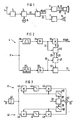
- Figur 1
- das Prinzipschaltbild eines Fernsehgeräts,
- Figur 2
- das Prinzipschaltbild einer erfindungsgemäßen Zwischenfrequenzdemodulationsstufe und
- Figur 3
- das Prinzipschaltbild einer Schaltung zur Phasennachführung.
Claims (6)
- Schaltungsanordnung zur Zwischenfrequenzdemodulation für ein Videosignalverarbeitungsgerät enthaltend:dadurch gekennzeichnet, daßein erstes Filter (20) mit Bandpaßcharakteristik, dem ein bei der Zwischenfrequenz liegendes Eingangssignal (IF) zuführbar ist und durch das ein Videosignal in Zwischenfrequenzlage erzeugt wird,ein zweites Filter (25) mit Bandpaßcharakteristik, dem das Eingangssignal (IF) zuführbar ist und durch das ein Videoträgersignal erzeugt wird,einen Demodulator (22), durch den das Videosignal in Zwischenfrequenzlage in das Basisband (FBAS) umgesetzt wird,ein Oszillator (27) vorgesehen ist, dem das Videoträgersignal zugeführt wird und durch den ein an das Videoträgersignal frequenzgekoppeltes Referenzsignal und ein dazu um 90° phasenverschobenes Referenzsignal erzeugt werden,ein erster und zweiter Mischer (43, 45) vorgesehen sind, denen jeweils das Referenzsignal zugeführt wird,dem ersten Mischer (43) das Videosignal in der Zwischenfrequenzlage zugeführt wird,dem zweiten Mischer (45) das über ein Filter (44) mit Tiefpaßcharakteristik geführte Ausgangssignal des ersten Mischers (43) zugeführt wird,ein dritter und vierter Mischer (46, 48) vorgesehen sind, denen jeweils das um 90° phasenverschobene Referenzsignal zugeführt wird,dem dritten Mischer (46) das Videosignal in der Zwischenfrequenzlage zugeführt wird,dem vierten Mischer (48) das über ein weiteres Filter (47) mit Tiefpaßcharakteristik geführte Ausgangssignal des dritten Mischers (46) zugeführt wird,die Ausgangssignale des zweiten und des vierten Mischers (45, 48) addiert und dem Demodulator (22) zugeführt werden,die Filter (44, 47) mit Tiefpaßcharakteristik derart dimensioniert sind, daß sie im wesentlichen jeweils nur für einen Gleichsignalanteil durchlässig sind.
- Schaltungsanordnung nach Anspruch 1,
dadurch gekennzeichnet, daß
zwischen das erste Filter (20) mit Bandpaßcharakteristik und den Demodulator (22) ein Regelverstärker (21) geschaltet ist und daß zwischen das zweite Filter (25) mit Bandpaßcharakteristik und den Oszillator (27) ein Regelverstärker (26) geschaltet ist. - Schaltungsanordnung nach einem der Ansprüche 1 oder 2,
dadurch gekennzeichnet, daß
das Videosignal in Zwischenfrequenzlage dem ersten und dem dritten Mischer (43, 46) über einen Begrenzer (40) zugeführt wird. - Schaltungsanordnung nach einem der Ansprüche 1 bis 3,
dadurch gekennzeichnet, daß
das Referenzsignal und das um 90° phasenverschobene Referenzsignal den Mischern (43, 45; 46, 48) über je ein Tiefpaßfilter (49, 50) zugeführt werden. - Schaltungsanordnung nach einem der Ansprüche 1 bis 4,
dadurch gekennzeichnet, daß
ein Filter (25) mit Bandpaßcharakteristik vorgesehen ist, dem das Eingangssignal (IF) zuführbar ist und durch das ein Tonträgersignal in Zwischenfrequenzlage erzeugt wird, und ein Mischer (32), dem das Tonträgersignal und eines der Referenzsignale zugeführt werden und durch den der Tonträger (TT) erzeugt wird. - Gerät zur Videosignalverarbeitung, enthaltend eine Schaltungsanordnung zur Zwischenfrequenzdemodulation nach einem der Ansprüche 1 bis 5, enthaltend: Mittel (2, 3) zur Erzeugung des bei der Zwischenfrequenz liegenden Eingangssignals (IF), das der Schaltungsanordnung zugeführt wird, Mittel (5) zur Signalverarbeitung der Videosignale im Basisband für die Anzeige an einem Bildschirm (6) und den Bildschirm (6), dem die verarbeiteten Videosignale zugeführt werden.
Applications Claiming Priority (2)
| Application Number | Priority Date | Filing Date | Title |
|---|---|---|---|
| DE4427018 | 1994-07-29 | ||
| DE4427018A DE4427018A1 (de) | 1994-07-29 | 1994-07-29 | Schaltungsanordnung zur Zwischenfrequenzdemodulation |
Publications (3)
| Publication Number | Publication Date |
|---|---|
| EP0695087A2 EP0695087A2 (de) | 1996-01-31 |
| EP0695087A3 EP0695087A3 (de) | 1996-06-05 |
| EP0695087B1 true EP0695087B1 (de) | 1999-03-24 |
Family
ID=6524522
Family Applications (1)
| Application Number | Title | Priority Date | Filing Date |
|---|---|---|---|
| EP95110352A Expired - Lifetime EP0695087B1 (de) | 1994-07-29 | 1995-07-03 | Schaltungsanordnung zur Zwischenfrequenzdemodulation für ein Videosignalverarbeitungsgerät |
Country Status (4)
| Country | Link |
|---|---|
| US (1) | US5648823A (de) |
| EP (1) | EP0695087B1 (de) |
| DE (2) | DE4427018A1 (de) |
| ES (1) | ES2132462T3 (de) |
Families Citing this family (4)
| Publication number | Priority date | Publication date | Assignee | Title |
|---|---|---|---|---|
| DE19814806A1 (de) * | 1998-04-02 | 1999-10-07 | Philips Patentverwaltung | Schaltungsanordnung zur Demodulation eines Zwischenfrequenz-Videosignals |
| JP2005534203A (ja) * | 2001-10-16 | 2005-11-10 | 株式会社RfStream | モノリシック集積回路上に受信機を実施するための方法および装置 |
| DE10302647A1 (de) * | 2003-01-23 | 2004-08-19 | Fraunhofer-Gesellschaft zur Förderung der angewandten Forschung e.V. | Vorrichtung und Verfahren zum Abwärtsmischen eines Eingangssignals in ein Ausgangssignal |
| US11445405B1 (en) * | 2021-06-17 | 2022-09-13 | Sprint Spectrum L.P. | Method and system for concurrently transmitting signals |
Family Cites Families (10)
| Publication number | Priority date | Publication date | Assignee | Title |
|---|---|---|---|---|
| US4091410A (en) * | 1976-11-08 | 1978-05-23 | Zenith Radio Corporation | Frequency and phase lock loop synchronous detecting system having a pair of phase lock conditions |
| JPS5676637A (en) * | 1979-11-29 | 1981-06-24 | Fujitsu Ltd | Phase synchronizing circuit |
| NL8301179A (nl) * | 1983-04-01 | 1984-11-01 | Philips Nv | Ontvanger voor hf-signalen voorzien van een paar parallelle signaalwegen. |
| NL8301651A (nl) * | 1983-05-10 | 1984-12-03 | Philips Nv | Menginrichting voorzien van eerste en tweede kwadratuurmengtrappen. |
| GB2191367B (en) * | 1986-05-29 | 1990-04-11 | Rca Corp | Circuitry for reducing demodulation phase error as for an automatic deghosting system |
| DE3764361D1 (de) * | 1987-03-14 | 1990-09-20 | Itt Ind Gmbh Deutsche | Fernsehsignal-frequenzumsetzungsschaltung. |
| US4796102A (en) * | 1987-08-03 | 1989-01-03 | Motorola, Inc. | Automatic frequency control system |
| NL8800555A (nl) * | 1988-03-07 | 1989-10-02 | Philips Nv | Synchrone demodulatieschakeling voor een op een draaggolf gemoduleerd televisiesignaal. |
| EP0478821B1 (de) * | 1990-10-02 | 1995-09-06 | Siemens Aktiengesellschaft | Einrichtung zur Synchrondemodulation amplitudenmodulierter Signale |
| SG44865A1 (en) * | 1991-05-10 | 1997-12-19 | Philips Electronics Nv | Television receiver with automatic tuning control |
-
1994
- 1994-07-29 DE DE4427018A patent/DE4427018A1/de not_active Ceased
-
1995
- 1995-07-03 DE DE59505418T patent/DE59505418D1/de not_active Expired - Lifetime
- 1995-07-03 ES ES95110352T patent/ES2132462T3/es not_active Expired - Lifetime
- 1995-07-03 EP EP95110352A patent/EP0695087B1/de not_active Expired - Lifetime
- 1995-07-31 US US08/509,411 patent/US5648823A/en not_active Expired - Lifetime
Also Published As
| Publication number | Publication date |
|---|---|
| ES2132462T3 (es) | 1999-08-16 |
| EP0695087A2 (de) | 1996-01-31 |
| DE4427018A1 (de) | 1996-02-08 |
| EP0695087A3 (de) | 1996-06-05 |
| US5648823A (en) | 1997-07-15 |
| DE59505418D1 (de) | 1999-04-29 |
Similar Documents
| Publication | Publication Date | Title |
|---|---|---|
| DE69031160T2 (de) | Homodyn-Empfänger für Kabelfernsehumsetzer | |
| DE3001765C2 (de) | Pilotsignal-Diskriminator | |
| DE3913593C2 (de) | Schaltungsanordnung zur Umsetzung eines empfangenen modulierten Informationssignals in ein Zwischenfrequenzsignal | |
| DE69018830T2 (de) | Übertragung von zusätzlichen informationen in einem fernsehsignal. | |
| DE69604648T2 (de) | Fernsehturner mit grosser bandbreite mit einem einzigen uberlagerungsoszillator | |
| DE2945563C2 (de) | ||
| DE3779638T2 (de) | Empfaenger mit parallelen signalstrecken. | |
| DE69021427T2 (de) | Tonsignalverarbeitungssystem. | |
| DE69530435T2 (de) | Demodulationsanordnung für einen hochauflösenden Fernsehempfänger | |
| EP0146749B1 (de) | Verfahren und Schaltungsanordnung zur Feststellung des Vorhandenseins oder Nichtvorhandenseins mindestens einer Frequenz bekannten Wertes in einem aus mehreren Frequenzen zusammengesetzten Eingangssignal | |
| DE3338993C2 (de) | Anordnung zur Demodulation des Fernsehtons | |
| DE3240565C2 (de) | Direktmischender Synchronempfänger | |
| DE69120101T2 (de) | Quasiparallele ZF-Verarbeitung mit gemeinsamem akustischem Oberflächenwellenfilter | |
| EP0695087B1 (de) | Schaltungsanordnung zur Zwischenfrequenzdemodulation für ein Videosignalverarbeitungsgerät | |
| DE1512222C2 (de) | Fernseh-Übertragungssystem | |
| DE69918606T2 (de) | Direktrundfunkübertragungssatellitenempfänger | |
| EP1657917B1 (de) | Verfahren und Schaltungsanordnung zur Kanalfilterung analog oder digital modulierter TV-Signale | |
| EP0127918B1 (de) | Fernsehempfänger mit einem Verarbeitungsteil zum Aufbereiten von Stereo-/Zweiton-Signalen | |
| EP0356555B1 (de) | Verfahren und Schaltungsanordnung zur Feststellung des Vorhandenseins oder Nichtvorhandenseins mindestens einer Frequenz bekannten Wertes in einem aus mehreren Frequenzen zusammengesetzten Eingangssignal | |
| DE69518134T2 (de) | Signaldetektorvorrichtung | |
| EP0349660B1 (de) | Frequenzumsetzungsschaltung für einen Farbfernsehkanal | |
| DE1108735B (de) | Schaltungsanordnung fuer einen Farbfernsehempfaenger | |
| DE2305463C3 (de) | Aufzeichnungsträger, auf dem eine Fernsehaufzeichnung gespeichert ist, Anwendungsverfahren für diesen Aufzeichnungsträger und Wiedergabegerät | |
| DE2904565A1 (de) | Mehrnormen-fernsehempfangsgeraet | |
| EP0445664B1 (de) | Schaltungsanordnung zum Detektieren von Kennschwingungen |
Legal Events
| Date | Code | Title | Description |
|---|---|---|---|
| PUAI | Public reference made under article 153(3) epc to a published international application that has entered the european phase |
Free format text: ORIGINAL CODE: 0009012 |
|
| AK | Designated contracting states |
Kind code of ref document: A2 Designated state(s): DE ES FR GB IT |
|
| PUAL | Search report despatched |
Free format text: ORIGINAL CODE: 0009013 |
|
| AK | Designated contracting states |
Kind code of ref document: A3 Designated state(s): DE ES FR GB IT |
|
| 17P | Request for examination filed |
Effective date: 19961104 |
|
| GRAG | Despatch of communication of intention to grant |
Free format text: ORIGINAL CODE: EPIDOS AGRA |
|
| GRAG | Despatch of communication of intention to grant |
Free format text: ORIGINAL CODE: EPIDOS AGRA |
|
| GRAH | Despatch of communication of intention to grant a patent |
Free format text: ORIGINAL CODE: EPIDOS IGRA |
|
| 17Q | First examination report despatched |
Effective date: 19980814 |
|
| GRAH | Despatch of communication of intention to grant a patent |
Free format text: ORIGINAL CODE: EPIDOS IGRA |
|
| GRAA | (expected) grant |
Free format text: ORIGINAL CODE: 0009210 |
|
| AK | Designated contracting states |
Kind code of ref document: B1 Designated state(s): DE ES FR GB IT |
|
| REF | Corresponds to: |
Ref document number: 59505418 Country of ref document: DE Date of ref document: 19990429 |
|
| ET | Fr: translation filed | ||
| GBT | Gb: translation of ep patent filed (gb section 77(6)(a)/1977) |
Effective date: 19990527 |
|
| REG | Reference to a national code |
Ref country code: ES Ref legal event code: FG2A Ref document number: 2132462 Country of ref document: ES Kind code of ref document: T3 |
|
| PLBE | No opposition filed within time limit |
Free format text: ORIGINAL CODE: 0009261 |
|
| STAA | Information on the status of an ep patent application or granted ep patent |
Free format text: STATUS: NO OPPOSITION FILED WITHIN TIME LIMIT |
|
| 26N | No opposition filed | ||
| REG | Reference to a national code |
Ref country code: GB Ref legal event code: IF02 |
|
| PGFP | Annual fee paid to national office [announced via postgrant information from national office to epo] |
Ref country code: ES Payment date: 20030718 Year of fee payment: 9 |
|
| PG25 | Lapsed in a contracting state [announced via postgrant information from national office to epo] |
Ref country code: ES Free format text: LAPSE BECAUSE OF NON-PAYMENT OF DUE FEES Effective date: 20040705 |
|
| PG25 | Lapsed in a contracting state [announced via postgrant information from national office to epo] |
Ref country code: IT Free format text: LAPSE BECAUSE OF NON-PAYMENT OF DUE FEES;WARNING: LAPSES OF ITALIAN PATENTS WITH EFFECTIVE DATE BEFORE 2007 MAY HAVE OCCURRED AT ANY TIME BEFORE 2007. THE CORRECT EFFECTIVE DATE MAY BE DIFFERENT FROM THE ONE RECORDED. Effective date: 20050703 |
|
| REG | Reference to a national code |
Ref country code: ES Ref legal event code: FD2A Effective date: 20040705 |
|
| REG | Reference to a national code |
Ref country code: GB Ref legal event code: 732E Free format text: REGISTERED BETWEEN 20110707 AND 20110713 |
|
| REG | Reference to a national code |
Ref country code: FR Ref legal event code: TP Owner name: INFINEON TECHNOLOGIES AG, DE Effective date: 20110922 |
|
| REG | Reference to a national code |
Ref country code: DE Ref legal event code: R081 Ref document number: 59505418 Country of ref document: DE Owner name: INFINEON TECHNOLOGIES AG, DE Free format text: FORMER OWNER: SIEMENS AKTIENGESELLSCHAFT, 80333 MUENCHEN, DE Effective date: 20111107 |
|
| PGFP | Annual fee paid to national office [announced via postgrant information from national office to epo] |
Ref country code: DE Payment date: 20140916 Year of fee payment: 20 |
|
| PGFP | Annual fee paid to national office [announced via postgrant information from national office to epo] |
Ref country code: FR Payment date: 20140721 Year of fee payment: 20 Ref country code: GB Payment date: 20140721 Year of fee payment: 20 |
|
| REG | Reference to a national code |
Ref country code: DE Ref legal event code: R071 Ref document number: 59505418 Country of ref document: DE |
|
| REG | Reference to a national code |
Ref country code: GB Ref legal event code: PE20 Expiry date: 20150702 |
|
| PG25 | Lapsed in a contracting state [announced via postgrant information from national office to epo] |
Ref country code: GB Free format text: LAPSE BECAUSE OF EXPIRATION OF PROTECTION Effective date: 20150702 |