EP0695014B1 - Garnitur für die Verbindung von Niederspannungsenergiekabeln - Google Patents
Garnitur für die Verbindung von Niederspannungsenergiekabeln Download PDFInfo
- Publication number
- EP0695014B1 EP0695014B1 EP95401740A EP95401740A EP0695014B1 EP 0695014 B1 EP0695014 B1 EP 0695014B1 EP 95401740 A EP95401740 A EP 95401740A EP 95401740 A EP95401740 A EP 95401740A EP 0695014 B1 EP0695014 B1 EP 0695014B1
- Authority
- EP
- European Patent Office
- Prior art keywords
- envelope
- cables
- accessory
- connection
- accessory according
- Prior art date
- Legal status (The legal status is an assumption and is not a legal conclusion. Google has not performed a legal analysis and makes no representation as to the accuracy of the status listed.)
- Expired - Lifetime
Links
Images


Classifications
-
- H—ELECTRICITY
- H02—GENERATION; CONVERSION OR DISTRIBUTION OF ELECTRIC POWER
- H02G—INSTALLATION OF ELECTRIC CABLES OR LINES, OR OF COMBINED OPTICAL AND ELECTRIC CABLES OR LINES
- H02G15/00—Cable fittings
- H02G15/08—Cable junctions
- H02G15/18—Cable junctions protected by sleeves, e.g. for communication cable
Definitions
- the invention lies in the technical field of low voltage power cables, and more specifically their connection.
- connection indicates especially the junction of two cables, or the connection of a branch cable on a main cable, i.e. a simple branch, or the connection of two branch cables on a main cable, i.e. a double branch.
- connection itself consists first of all in strip the basic conductors of the various cables put into play, and then to connect them according to the nature of the operation. Once the connections have been made, a housing rigid is then put in place as described in EP-A 0 542 010.
- the casing is often filled with a material of insulation cast or injected in situ, which is generally a resin of the epoxy or polyurethane type. Apart from the fact that that such a packing lengthens the connection operation, different disadvantages are inherent in the very nature of the filling material.
- Another solution is to perform a series tape around the connection area.
- the invention relates to an accessory ensuring a connection without flame, simple and durable, while allowing get rid of the use of a filling material.
- the invention relates to a accessory for cold connection of low voltage cables, adapted to be arranged around a connection area comprising two lateral zones where the cables are sheathed, and an intermediate connection area, and comprising a envelope covering the intermediate area and fixed with tightly at both of its side ends on each of a pair of rigid flanges arranged at each lateral zone and each provided with at least one housing allowing the crossing of a corresponding number sheathed cables, said accessory being characterized in that that the envelope is an elastic envelope provided with pleats longitudinal and made of a folded sheet marrying tightly shaped cables and connectors, closed to its two longitudinal ends via a tenon-mortise connection.
- the accessory according to the invention allows achieve the objectives mentioned above. Indeed, it ensures a perfectly sealed cold connection and sustainable.
- the accessory does not require the use of a filling material.
- This accessory allows the connection of a cable branch on a main cable.
- a junction or double bypass accessory is possible to consider, without departing from the scope of the invention.
- the accessory consists of an intermediate casing 12 and two side flanges 14. These flanges are formed for example of two complementary half-pieces and are made of metallic or plastic material.
- the first 14 1 of these flanges is intended to fit one end of the main cable and the branch cable. To this end, it is provided with two circular housings 16 1 , 16 2 for crossing the cables, arranged one next to the other. These housings have a U-shaped profile 18 in which seals 20 made of elastomeric material are housed, making it possible to seal with the outer sheath of the cables entering each housing.
- the flange 14 1 is extended in the direction of the intermediate zone, by a flat 22 cooperating with the end of the envelope in order to ensure perfect sealing of their mutual connection, as described below.
- the envelope 12 is for example made up of a elastomer sheet having a thickness of about 6mm.
- the envelope is provided longitudinal folds 23 which, like a bellows, allow to better match the external volume of the connectors and cables, between the two flanges.
- the envelope can also be provided with folds transversal ensuring a possibility of bending, by example when the two side flanges are not parallel.
- the sheet constituting the envelope 12 is folded in on itself and is attached to its two lateral ends 24, on the respective flats 22 of the flanges 14.
- the closure of the envelope at its two longitudinal ends 26 is provided via a tenon-mortise connection 28 reinforced by a clip tightening 29.
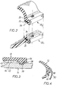
- FIG. 2 A variant of closing the envelope is described in FIG. 2.
- Two flats 30 1 and 30 2 extending outwards are produced at the longitudinal ends 26 of the envelope 12. These flats are provided with holes 32 allowing the passage of fixing means such as for example screws not shown.
- the tightness of the closure is improved by providing a double groove seal 34 on one of the flats 30 1. When the envelope is closed, the latter is crushed on the flat wall of the corresponding flat 30 2 and ensures increased sealing.
- Two metal inserts 35 are furthermore inserted within each flat, in order to ensure their stiffness and improve the crushing of the double joint throat.
- Figure 3 shows more precisely the fixing the lateral end 24 of the casing 12 to the flat 22 of flange 14.
- a groove 36 is formed in the flat 22, in order to receive a projection 38 of the envelope, so as to make a tenon-mortise connection.
- Sealing is ensured through minus a groove seal 40 (two in the example described). These seals are provided at the internal surface 42 of the envelope, facing the flat outer surface 44 of the flange 14. Sealing is improved by impregnating the area of contact between the groove and the projection by means of a sealant like putty.
- the envelope is provided with fingers 46 which consist of a metal insert protruding from one of the longitudinal ends of the envelope (see Figure 4).
- Each finger cooperates with a corresponding flexible tongue 48 made on the other longitudinal end of the enclosure, and provided with a hole 50 allowing it to be fixed on the finger.
- Figure 5 illustrates the positioning of the casing once the accessory has been fitted.
- the three phases 52 1 , 52 2 , 52 3 as well as the neutral 52 4 of the main cable are connected to the respective phases 54 1 , 54 2 , 54 3 and to the neutral 54 4 branched cable, via connectors 56 1 , 56 2 , 56 3 and 56 4 .
- the casing 12 conforms as best as possible to the external contours of all of the connectors, so as to minimize the residual air volume and, in fact, the overall size of the accessory.
Landscapes
- Cable Accessories (AREA)
Claims (5)
- Ausstattung zum Kaltverbinden von Niederspannungsstromkabeln, welche so ausgelegt ist, daß sie um einen Verbindungsbereich herum angeordnet wird, der zwei Seitenbereiche, in denen die Kabel ummantelt sind, und einen Zwischenbereich für den Anschluß aufweist, und welche einen Mantel (12) aufweist, der den Zwischenbereich umhüllt und der auf dichte Weise mit seinen beiden seitlichen Enden (24) auf jedem Flansch eines Paares von starren Flanschen (14) befestigt ist, die auf der Höhe jedes Seitenbereiches angeordnet sind und die jeweils mit mindestens einer Ausnehmung (16) versehen sind, die den Durchgang einer entsprechenden Anzahl von ummantelten Kabeln erlaubt, dadurch gekennzeichnet, daß der Mantel (12) ein elastischer Mantel ist, der mit längsverlaufenden Falten (23) versehen ist und aus einer umgeschlagenen Folie besteht, die sich eng an die Form der Kabel und der Verbinder anpaßt und die an ihren beiden Längsenden (26) durch eine Nut-Steckfuß-Verbindung (28) geschlossen ist.
- Ausstattung nach Anspruch 1, dadurch gekennzeichnet, daß die Längsenden (26) des Mantels (12) Abflachungen (30) aufweisen, die mit Löchern (32) für den Durchgang von Befestigungseinrichtungen versehen sind, wobei eine Doppelkehlverbindung (34) in einer (30) der Abflachungen angeordnet ist.
- Ausstattung nach den vorhergehenden Ansprüchen 1 und 2, dadurch gekennzeichnet, daß der Flansch (14) mit einer Nut (36) versehen ist, die einen entsprechenden Vorsprung (38) des Mantels (12) aufnimmt.
- Ausstattung nach Anspruch 3, dadurch gekennzeichnet, daß mindestens eine Doppelkehlverbindung (40) an der Innenfläche (42) des Mantels gegenüber der Außenfläche (44) des Flansches (14) angeordnet ist.
- Ausstattung nach Anspruch 1, dadurch gekennzeichnet, daß der Mantel (12) mit mindestens einem Positionierungsfinger (46) versehen ist, der mit einer nachgiebigen Lasche (48) zusammenwirkt, die mit einem Loch (50) versehen ist.
Applications Claiming Priority (2)
| Application Number | Priority Date | Filing Date | Title |
|---|---|---|---|
| FR9409422A FR2723271B1 (fr) | 1994-07-29 | 1994-07-29 | Accessoire de raccordement de cables d'energie basse tension |
| FR9409422 | 1994-07-29 |
Publications (2)
| Publication Number | Publication Date |
|---|---|
| EP0695014A1 EP0695014A1 (de) | 1996-01-31 |
| EP0695014B1 true EP0695014B1 (de) | 1998-09-02 |
Family
ID=9465889
Family Applications (1)
| Application Number | Title | Priority Date | Filing Date |
|---|---|---|---|
| EP95401740A Expired - Lifetime EP0695014B1 (de) | 1994-07-29 | 1995-07-24 | Garnitur für die Verbindung von Niederspannungsenergiekabeln |
Country Status (5)
| Country | Link |
|---|---|
| US (1) | US5824956A (de) |
| EP (1) | EP0695014B1 (de) |
| DE (1) | DE69504439T2 (de) |
| ES (1) | ES2123932T3 (de) |
| FR (1) | FR2723271B1 (de) |
Families Citing this family (10)
| Publication number | Priority date | Publication date | Assignee | Title |
|---|---|---|---|---|
| FR2756434B1 (fr) * | 1996-11-25 | 2000-02-18 | Pirelli Cables Sa | Dispositif de protection de raccordement de cables |
| FR2760145B1 (fr) * | 1997-02-21 | 1999-04-09 | Telecommunications Sa | Dispositif d'etancheite et de protection fendu retractable a froid |
| US6545219B1 (en) * | 2000-04-24 | 2003-04-08 | Tyco Electronics Corporation | Wrap-around cable sleeves having an expandable body portion and methods of making same |
| US6706968B2 (en) | 2000-04-24 | 2004-03-16 | Tyco Electronics Corporation | Environmentally sealed wrap-around sleeves having a longitudinal sealant chamber |
| GB0102976D0 (en) | 2001-02-07 | 2001-03-21 | Tyco Electronics Raychem Nv | Enclosing device and method |
| US6955558B1 (en) * | 2004-04-26 | 2005-10-18 | Andrew Corporation | Cable and apparatus interface security device |
| NL1027997C2 (nl) * | 2005-01-11 | 2006-07-12 | Filoform Bv | Leidingverbinding en samenstel en werkwijze voor afdichting daarvan. |
| US7453042B2 (en) * | 2007-04-09 | 2008-11-18 | Andrew Llc | Cable and apparatus interconnection close quarters environmental seal |
| US8415564B2 (en) | 2009-11-04 | 2013-04-09 | Tyco Electronics Corporation | Wrap-around cable sleeve assemblies and methods for making and using the same |
| KR101837210B1 (ko) * | 2009-12-24 | 2018-03-09 | 델피 인터내셔널 오퍼레이션즈 룩셈부르크 에스.에이 알.엘. | 케이블 접합부 |
Family Cites Families (10)
| Publication number | Priority date | Publication date | Assignee | Title |
|---|---|---|---|---|
| US3836694A (en) * | 1972-07-24 | 1974-09-17 | H Kapell | Re-enterable splice enclosure |
| DE7423507U (de) * | 1974-07-10 | 1974-11-14 | Siemens Ag | Kabelmuffe |
| GB1547975A (en) * | 1975-11-21 | 1979-07-04 | Wettern Electric Ltd | Joint boxes encapsulating cable joints |
| ZA861765B (en) * | 1985-03-14 | 1986-10-29 | Trygve Eric Hvidsten | Cable splice closure |
| DE3689459D1 (de) * | 1985-10-14 | 1994-02-10 | Siemens Ag | Kabelmuffe mit stirnseitigen Dichtungskörpern und einem längsgeschlitzten Muffenrohr. |
| US4769513A (en) * | 1986-06-10 | 1988-09-06 | Raychem Corporation | Splice closure system |
| CA1302531C (en) * | 1987-04-06 | 1992-06-02 | N.V. Raychem S.A. | Splice case |
| TR24079A (tr) * | 1988-11-09 | 1991-03-01 | Raychem Sa Nv | Kapama duezenegi |
| GB9107377D0 (en) * | 1991-04-08 | 1991-05-22 | Raychem Sa Nv | Environmental protection |
| DE4137206A1 (de) * | 1991-11-12 | 1993-05-13 | Stewing Kunststoff | Kabelmuffe zum verbinden und abzweigen von kabeln, insbesondere fernmeldekabeln |
-
1994
- 1994-07-29 FR FR9409422A patent/FR2723271B1/fr not_active Expired - Fee Related
-
1995
- 1995-07-24 DE DE69504439T patent/DE69504439T2/de not_active Expired - Lifetime
- 1995-07-24 EP EP95401740A patent/EP0695014B1/de not_active Expired - Lifetime
- 1995-07-24 ES ES95401740T patent/ES2123932T3/es not_active Expired - Lifetime
-
1997
- 1997-09-23 US US08/935,798 patent/US5824956A/en not_active Expired - Lifetime
Also Published As
| Publication number | Publication date |
|---|---|
| DE69504439T2 (de) | 1999-04-01 |
| EP0695014A1 (de) | 1996-01-31 |
| ES2123932T3 (es) | 1999-01-16 |
| FR2723271A1 (fr) | 1996-02-02 |
| FR2723271B1 (fr) | 1998-01-30 |
| US5824956A (en) | 1998-10-20 |
| DE69504439D1 (de) | 1998-10-08 |
Similar Documents
| Publication | Publication Date | Title |
|---|---|---|
| EP0695014B1 (de) | Garnitur für die Verbindung von Niederspannungsenergiekabeln | |
| FR2688860A1 (fr) | Organe de drainage etanche pour circuit hydraulique. | |
| FR2508986A1 (fr) | Collier de serrage de tubes | |
| FR2713305A1 (fr) | Dispositif de raccord rapide pour tubulures d'échangeur de chaleur. | |
| FR2762455A1 (fr) | Piece de raccordement etanche d'un tube a l'orifice d'une paroi | |
| FR2554645A1 (fr) | Capot arriere de connecteur electrique | |
| FR2723162A1 (fr) | Joint annulaire d'etancheite | |
| EP0908992B1 (de) | Vorrichtung zur variablen Abdeckung von elektrischen kabelführungen | |
| FR2823603A1 (fr) | Appareil electrique etanche | |
| EP1251616A1 (de) | Abdichtung für elektrisches Kabel | |
| FR2557390A1 (fr) | Cable de moyenne tension, isole par du papier, ferme | |
| FR2710790A1 (fr) | Dispositif de traversée étanche. | |
| EP1143580B1 (de) | Elektrischer Steckverbinder | |
| FR2716298A1 (fr) | Perfectionnements aux connecteurs électriques. | |
| FR2901630A1 (fr) | Passe-barre | |
| KR200154911Y1 (ko) | 관 연결구 | |
| EP0844719A2 (de) | Vorrichtung zum Schutz von Kabelverbindungen | |
| EP0187062B1 (de) | Gehäuse eines elektrischen Apparates | |
| FR3039315B1 (fr) | Boitier pour fusible ameliore | |
| EP1565973B1 (de) | Vorrichtung zum verbinden von flexiblen rohrleitungen | |
| FR2469016A1 (fr) | Dispositif de connexion electrique pour cables | |
| FR2910731A1 (fr) | Dispositif d'eclissage de deux canalisations electriques. | |
| FR2734687A3 (fr) | Joint d'etancheite pour un boitier | |
| FR2466887A1 (fr) | Bouchon d'etancheite pour canalisation de cable electrique et procede s'y rapportant | |
| WO2020002265A1 (fr) | Assemblage d'un flexible d'echappement et d'un dispositif de protection |
Legal Events
| Date | Code | Title | Description |
|---|---|---|---|
| PUAI | Public reference made under article 153(3) epc to a published international application that has entered the european phase |
Free format text: ORIGINAL CODE: 0009012 |
|
| AK | Designated contracting states |
Kind code of ref document: A1 Designated state(s): DE ES FR GB IT |
|
| 17P | Request for examination filed |
Effective date: 19960611 |
|
| R17P | Request for examination filed (corrected) |
Effective date: 19960611 |
|
| 17Q | First examination report despatched |
Effective date: 19970303 |
|
| GRAG | Despatch of communication of intention to grant |
Free format text: ORIGINAL CODE: EPIDOS AGRA |
|
| GRAG | Despatch of communication of intention to grant |
Free format text: ORIGINAL CODE: EPIDOS AGRA |
|
| GRAH | Despatch of communication of intention to grant a patent |
Free format text: ORIGINAL CODE: EPIDOS IGRA |
|
| GRAH | Despatch of communication of intention to grant a patent |
Free format text: ORIGINAL CODE: EPIDOS IGRA |
|
| GRAA | (expected) grant |
Free format text: ORIGINAL CODE: 0009210 |
|
| AK | Designated contracting states |
Kind code of ref document: B1 Designated state(s): DE ES FR GB IT |
|
| REF | Corresponds to: |
Ref document number: 69504439 Country of ref document: DE Date of ref document: 19981008 |
|
| GBT | Gb: translation of ep patent filed (gb section 77(6)(a)/1977) |
Effective date: 19981105 |
|
| REG | Reference to a national code |
Ref country code: ES Ref legal event code: FG2A Ref document number: 2123932 Country of ref document: ES Kind code of ref document: T3 |
|
| PLBE | No opposition filed within time limit |
Free format text: ORIGINAL CODE: 0009261 |
|
| STAA | Information on the status of an ep patent application or granted ep patent |
Free format text: STATUS: NO OPPOSITION FILED WITHIN TIME LIMIT |
|
| 26N | No opposition filed | ||
| REG | Reference to a national code |
Ref country code: GB Ref legal event code: IF02 |
|
| REG | Reference to a national code |
Ref country code: GB Ref legal event code: 732E |
|
| REG | Reference to a national code |
Ref country code: GB Ref legal event code: 732E |
|
| PGFP | Annual fee paid to national office [announced via postgrant information from national office to epo] |
Ref country code: DE Payment date: 20140729 Year of fee payment: 20 |
|
| PGFP | Annual fee paid to national office [announced via postgrant information from national office to epo] |
Ref country code: FR Payment date: 20140717 Year of fee payment: 20 Ref country code: ES Payment date: 20140728 Year of fee payment: 20 Ref country code: GB Payment date: 20140729 Year of fee payment: 20 |
|
| PGFP | Annual fee paid to national office [announced via postgrant information from national office to epo] |
Ref country code: IT Payment date: 20140724 Year of fee payment: 20 |
|
| REG | Reference to a national code |
Ref country code: DE Ref legal event code: R071 Ref document number: 69504439 Country of ref document: DE |
|
| REG | Reference to a national code |
Ref country code: GB Ref legal event code: PE20 Expiry date: 20150723 |
|
| PG25 | Lapsed in a contracting state [announced via postgrant information from national office to epo] |
Ref country code: GB Free format text: LAPSE BECAUSE OF EXPIRATION OF PROTECTION Effective date: 20150723 |
|
| REG | Reference to a national code |
Ref country code: ES Ref legal event code: FD2A Effective date: 20151030 |
|
| PG25 | Lapsed in a contracting state [announced via postgrant information from national office to epo] |
Ref country code: ES Free format text: LAPSE BECAUSE OF EXPIRATION OF PROTECTION Effective date: 20150725 |