EP0695002B1 - Hybrid Faserverstärker - Google Patents
Hybrid Faserverstärker Download PDFInfo
- Publication number
- EP0695002B1 EP0695002B1 EP95109907A EP95109907A EP0695002B1 EP 0695002 B1 EP0695002 B1 EP 0695002B1 EP 95109907 A EP95109907 A EP 95109907A EP 95109907 A EP95109907 A EP 95109907A EP 0695002 B1 EP0695002 B1 EP 0695002B1
- Authority
- EP
- European Patent Office
- Prior art keywords
- gain
- fiber
- gain fiber
- stage
- amplifier
- Prior art date
- Legal status (The legal status is an assumption and is not a legal conclusion. Google has not performed a legal analysis and makes no representation as to the accuracy of the status listed.)
- Expired - Lifetime
Links
Images
Classifications
-
- H—ELECTRICITY
- H01—ELECTRIC ELEMENTS
- H01S—DEVICES USING THE PROCESS OF LIGHT AMPLIFICATION BY STIMULATED EMISSION OF RADIATION [LASER] TO AMPLIFY OR GENERATE LIGHT; DEVICES USING STIMULATED EMISSION OF ELECTROMAGNETIC RADIATION IN WAVE RANGES OTHER THAN OPTICAL
- H01S3/00—Lasers, i.e. devices using stimulated emission of electromagnetic radiation in the infrared, visible or ultraviolet wave range
- H01S3/05—Construction or shape of optical resonators; Accommodation of active medium therein; Shape of active medium
- H01S3/06—Construction or shape of active medium
- H01S3/063—Waveguide lasers, i.e. whereby the dimensions of the waveguide are of the order of the light wavelength
- H01S3/067—Fibre lasers
- H01S3/06754—Fibre amplifiers
- H01S3/06758—Tandem amplifiers
-
- H—ELECTRICITY
- H01—ELECTRIC ELEMENTS
- H01S—DEVICES USING THE PROCESS OF LIGHT AMPLIFICATION BY STIMULATED EMISSION OF RADIATION [LASER] TO AMPLIFY OR GENERATE LIGHT; DEVICES USING STIMULATED EMISSION OF ELECTROMAGNETIC RADIATION IN WAVE RANGES OTHER THAN OPTICAL
- H01S2301/00—Functional characteristics
- H01S2301/02—ASE (amplified spontaneous emission), noise; Reduction thereof
-
- H—ELECTRICITY
- H01—ELECTRIC ELEMENTS
- H01S—DEVICES USING THE PROCESS OF LIGHT AMPLIFICATION BY STIMULATED EMISSION OF RADIATION [LASER] TO AMPLIFY OR GENERATE LIGHT; DEVICES USING STIMULATED EMISSION OF ELECTROMAGNETIC RADIATION IN WAVE RANGES OTHER THAN OPTICAL
- H01S2301/00—Functional characteristics
- H01S2301/04—Gain spectral shaping, flattening
Definitions
- the present invention relates to a multi-wavelength optical fiber amplifier that is capable of providing high output power.
- Next generation lightwave networks will use fiber amplifiers which are formed of gain optical fibers, the cores of which contain a dopant such as rare earth ions. Such an amplifier receives an optical signal containing wavelength ⁇ s and a pump signal containing wavelength ⁇ p ; these signals are coupled to the gain fiber by means such as one or more couplers located at one or both ends of the amplifier.
- a multi-channel network such as a wavelength division multiplexed network, where two or more signals of different wavelengths are used to transmit information, each of the channels must have about the same gain. In a long haul transmission system, if the gain of one channel of each amplifier is different from that of another channel, serious problems can result.
- the signal of one channel A can be many dB greater than that of the signal of another channel B.
- This difference of signal level between the two channels can result in an optical transmission system which, at best, may be marginal in performance.
- channel A is at a level which provides a good signal to noise ratio
- the channel B signal which experiences less gain, may be at a signal level which has a very low signal to noise ratio.
- the signal to noise ratio of channel B may be too low for that channel to be useful.
- each amplifier can provide only a finite amount of power to the signals being amplified. While the power of the amplifier is available to both channels, frequently it is not divided equally between the two channels. Often, the larger of the two signals will capture a proportionately larger portion of the available power and leave a disproportionate smaller share of the available power for the weaker signal. Thus, the stronger signal gets progressively stronger, relative to the weaker signal, as the two signals advance through the amplifiers of a long haul transmission line.
- Serially connected fiber amplifiers can be provided with pump power from the same source.
- the pump power can be applied to the first stage, and residual pump power that is not used in the first stage can be coupled to the second stage.
- a 2x2 wavelength division multiplexer (WDM) coupler MUX II couples the pump energy to the second stage through a first path and couples the signal to the second stage through a second path that has a filter for attenuating the ASE.
- WDM wavelength division multiplexer
- Some signal can leak, due to the finite crosstalk of the WDM coupler, through the pump path to the second stage gain fiber in the same direction but out of synchronization with the principle signal, whereby the noise figure of the amplifier is degraded due to multipath interference (MPI).
- MPI multipath interference
- Configuration 2 of the Delavaux et al. publication the principle signal and the leakage signal propagate counterdirectionally through the gain fiber, whereby the particular source of MPI noise in configuration 1 is effectively eliminated in configuration 2.
- some signal after being amplified by the second stage gain fiber, can leak through the WDM coupler MUX II, due to its finite crosstalk, back into the first gain fiber. The amplified leakage signal is then coupled by WDM coupler MUX II to the input port or the pump port.
- An object of the present invention is to provide a fiber amplifier that overcomes the disadvantages of prior art devices, provides relatively high output power at a balanced gain spectrum within the operating wavelength window; to provide a fiber amplifier having a stage that utilizes remnant pump power from a previous stage and yet exhibits a low noise figure, including MPI noise.
- the present invention relates to a hybrid multistage fiber amplifier as defined in claim 1 having coupled input and output stages.
- the input stage has a given passive loss and a flattened gain spectrum.
- the output stage has a passive loss that is lower than the given passive loss and gain spectrum that is less flat than input stage.
- a multistage fiber amplifier comprises first and second gain fibers, each of which has first and second ends.
- a source of pump power and a signal are coupled to the first end of the first gain fiber.
- a first WDM coupler has an input terminal for receiving a signal and pump power and has a first output terminal to which most of the signal is coupled and a second output terminal to which most of the pump power is coupled.
- the second end of the first gain fiber is coupled to the input terminal of the first coupler.
- a filter connects the first output terminal of the first WDM coupler to the first end of the second gain fiber.
- An output device such as a second WDM coupler connects the second output terminal of the first coupler to the second end of the second gain fiber.
- any leakage signal propagating from the second output terminal of the first coupler to the second end of the second gain fiber propagates counterdirectionally through the second gain fiber with respect to the principal signal coupled to the second gain fiber from the first output terminal of the first coupler.
- the effect of such leakage signal on amplifier noise will be negligible.
- any of the amplified signal at the second end of the second gain fiber is inhibited from propagating to the first gain fiber because of the presence of the output device and the first WDM coupler in the path between the second end of the second gain fiber and the second end of the first gain fiber.
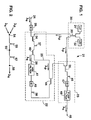
- Fig. 1 is a schematic illustration of a fiber amplifier embodying the present invention.
- Fig. 2 is a schematic illustration of a further embodiment of the invention.
- the present invention relates to a hybrid fiber amplifier design which employs two gain fibers having different compositions to achieve higher output power at a balanced gain spectrum within the operating wavelength window. Higher output power is achieved by trading off gain flatness. This can be accomplished in a systematic way to accommodate different system requirements.
- this invention applies to gain fibers employing any rare earth dopant for achieving signal amplification as well as any codopant used for the purpose of modifying the shape of its gain curve and/or for the purpose of facilitating the fabrication of the gain fiber.
- alumina has been employed to improve the solubility of erbium in a germania-silicate glass gain fiber core and to flatten the gain spectrum.
- in-line amplifier having a pre-amplification stage for amplifying the weak input signals and a power amplification output stage, both stages would employ high alumina content, flat gain spectrum fiber amplifiers when balanced gain spectrum was desired.
- passive loss increases with increasing alumina concentration. Therefore, computer modeling was employed for the purpose of analyzing modifications of this amplifier. More specifically, the analysis involved varying the compositions of the pre-amplifier and/or the power output stages.
- gain fibers having a lower passive loss are used close to the output of the multistage amplifier, while the higher loss, flat gain fiber (higher alumina concentration, for example) is used close the input.
- the exact combination, in terms of gain fiber lengths and compositions, is determined by the specific system requirements.
- the alumina concentration of the first stage should be at least about 2 wt. %, and that of the output stage should be no more than about 1 wt. %.
- a multistage fiber amplifier 21 comprises pre-amplifiction stage 22 and power-amplification stage 23.
- Amplifier 21 is pumped by a single source 30 which divides the pump power between the stages so that the amplifier achieves high pump power-to-signal conversion efficiency.
- Laser diodes 31 and 32 of source 30 are connected to a 3 dB coupler 33 which provides equal amounts of pump power to WDM couplers 34 and 35. The gain of the amplifier will drop by no more than 4 dB if one of the sources fails, due to the use of coupler 33 in the pump source.
- a signal of wavelength ⁇ s is coupled from input 24 to gain fiber 37 by isolator 29 and WDM coupler 34.
- the amplified signal is coupled to gain fiber 38 by WDM coupler 40 and path 26 which includes ASE filter 41 and isolator 42.
- the length of gain fiber 37 is insufficient to convert all of the pump power supplied thereto by couplers 33 and 34 to amplified signal and ASE.
- Gain fiber 37 might absorb only 50% of the pump power, for example.
- the remnant pump power from gain fiber 37 is connected to gain fiber 38 by coupler 40 and path 25 which includes one leg of coupler 44. This remnant pump power pumps gain fiber 38 in the reverse direction.
- an MPI source results from the leakage of amplified signal from gain fiber 38 through WDM coupler 44 back to gain fiber 37, and back reflected by the input connector or the pump laser facets.
- This MPI source can be significantly reduced (by at least the WDM coupler crosstalk) by using two 1x2 WDM couplers 40 and 44.
- couplers 40 and 44 is an improvement over Configuration 2 of the Delavaux et al. publication wherein a single 2x2 WDM coupler MUX II is employed to connect two gain fibers.
- the amplified signal is coupled from gain fiber 38 to gain fiber 45 by WDM couplers 44 and 35, coupler 35 supplying pump power to gain fiber 45.
- the amplified output from gain fiber 45 is connected to output 46 by isolator 47 and pump wavelength filter 48.
- Isolators 29, 42 and 47 suppress reflection noise.
- Optional pump filter 48 protects downstream elements from pump light that might be deleterious to them.
- first and second stage gain fibers 37 and 38 of pre-amplification stage 22 had 5 ⁇ m diameter cores formed of SiO 2 doped with 16.69 wt. % GeO 2 , 2.63 wt. % alumina and 0.07 wt. % erbium, whereby they had an optimum gain flatness of about 0.017 dB/dB between 1549 nm and 1561 nm and a passive loss of about 0.033 dB/m.
- the gain flatness for a given operating condition and for a given wavelength window e.g.
- Third stage gain fiber 45 of power amplifier 23 had a 4 ⁇ m diameter core formed of SiO 2 doped with 20.73 wt. % GeO 2 , 0.63 wt. % alumina and 0.03 wt. % erbium, whereby it had an optimum gain flatness of 0.051 dB/dB between 1549 nm and 1561 nm and a negligible passive loss.
- the gain fibers had a SiO 2 cladding having a diameter of 125 ⁇ m.
- gain fibers 37 and 38 of stages 1 and 2 exhibited a passive loss of 0.033dB/m, while the passive loss of low alumina content gain fiber 45 of stage 3 was negligibly small, i.e. the passive loss of a 10 m length of the fiber was too small to be measured.
- Laser diodes 31 and 32 provided pump power at a wavelength of 980 nm. Numerical modeling results show that this hybrid design yields 0.5 dB more output power, by trading off 0.3 dB gain flatness, as compared to a design that uses the high alumina content gain fiber for all three stages.
- the pre-amplification stage and the power amplification stage can each be formed of stages different in number from that illustrated in Fig. 1.
- the terms "pre-amplification stage” and "power amplification stage” as used herein have a functional rather than a physical connotation.
- the pre-amplification stage and the power amplification stage are embodied in a single physical amplifier stage in which two different gain fibers 55 and 57 are connected together by fusion splice 56.
- the higher loss, flat-gain spectrum gain fiber 55 is located close the signal input terminal 54, while the lower loss gain fiber 57 is located close to the output terminal 58.
- fiber 55 may have a higher alumina concentration than fiber 57, but this embodiment is not limited to this combination of gain fibers.
- gain fibers 55 and 57 can be forward pumped as illustrated in Fig. 2. However, gain fibers 55 and 57 could be reverse pumped or co-pumped by application of the pump power to the appropriate terminal or terminals by WDM couplers or the like.
- gain fibers having a higher NA have a better optical mode confinement for both the pump and the signal light. Such fibers are useful for achieving low noise and high gain operation in an input stage, especially in a low-pump power situation.
- NA fibers having a higher NA have higher loss caused by scattering. This higher loss limits the output power when such a gain fiber is used in the output stage.
- gain fibers with a tighter Er confinement (Er confined within a small radius at the center of the fiber core) are effectively used in the input stage to assure high inversion, but they are not useful for the output stage due to the higher loss resulting from the longer length of gain fiber needed to achieve the same amount of gain (at constant Er concentration). Therefore, gain fibers with higher NA and tighter Er confinement should be used close to the input, while gain fibers with lower NA and less confined Er ions should be used close to the output.
- erbium-doped flurozirconate glass has an extremely flat gain spectrum.
- fluoride base glasses are disclosed at pages 38 to 44 of Optical Properties of Glass , edited by D.R. Uhlmann and N.J. Kreidl, published by the American Ceramic Society, Inc.
- the use of rare-earth-doped fluorozirconate glasses for fiber amplifiers is discussed in the publication "Lightwave", vol. 11, No. 8, July 1994, p. 6.
- erbium-doped flurozirconate glass is relatively lossy at wavelengths in the 1555 nm range
- that gain fiber would be employed at the input stage of the fiber amplifier while a low loss gain fiber such as a Ge-Er-doped SiO 2 gain fiber containing less than about 5 wt. % alumina could be used at the output stage.
Landscapes
- Physics & Mathematics (AREA)
- Electromagnetism (AREA)
- Engineering & Computer Science (AREA)
- Plasma & Fusion (AREA)
- Optics & Photonics (AREA)
- Lasers (AREA)
Claims (12)
- Mehrstufiger Glasfaserverstärker (21) miteiner Eingangsstufe (22), die einen vorgegebenen passiven Verlust und ein abgeflachtes Verstärkungsspektrum aufweist, und miteiner Ausgangsstufe (23), die an die Eingangsstufe gekoppelt ist, wobei die Ausgangsstufe einen passiven Verlust aufweist, der niedriger ist als der vorgegebene passive Verlust, und ein Verstärkungsspektrum, das weniger flach ist als das der Eingangsstufe.
- Mehrstufiger Glasfaserverstärker nach Anspruch 1, bei dem die Eingangsstufe eine erste Verstärkungsglasfaser (37) aufweist, die mit aktiven Dotierungsionen dotiert ist,
welche zur Hervorrufung einer stimulierten Lichtemission innerhalb eines vorbestimmten Wellenlängenbandes fähig sind, und mit einem weiteren Co-Dotierungsstoff, welcher das Verstärkungsspektrum der ersten Verstärkungsglasfaser abflacht. - Mehrstufiger Glasfaserverstärker nach Anspruch 2, bei dem die Ausgangsstufe eine zweite Verstärkungsglasfaser (45) aufweist, die mit aktiven Dotierungsionen dotiert ist,
welche zur Hervorrufung einer stimulierten Lichtemission innerhalb eines vorbestimmten Wellenlängenbandes fähig sind, und mit einem Co-Dotierungsstoff, welcher das Verstärkungsspektrum der zweiten Verstärkungsglasfaser abflacht, wobei die zweite Verstärkungsglasfaser eine niedrigere Konzentration des Co-Dotierungsstoffes besitzt als die erste Verstärkungsglasfaser. - Mehrstufiger Glasfaserverstärker nach Anspruch 1, bei dem die Eingangsstufe eine erste Verstärkungsglasfaser (37) aufweist, die mit aktiven Dotierungsionen dotiert ist,
welche innerhalb eines ersten Radius begrenzt liegen, und
wobei die Ausgangsstufe eine zweite Verstärkungsglasfaser (45) aufweist, die mit aktiven Dotierungsionen dotiert ist, welche innerhalb eines Radius begrenzt liegen, der größer ist als der erste Radius. - Mehrstufiger Glasfaserverstärker nach Anspruch 1, bei dem die Eingangsstufe eine erste Verstärkungsglasfaser (37) aufweist, deren Zusammensetzung ein Fluorzirkonatglas aufweist, wobei die Glasfaser einen Kern besitzt, der mit aktiven Dotierungsionen dotiert ist.
- Mehrstufiger Glasfaserverstärker nach Anspruch 1, bei dem die Eingangsstufe aus einer Vorverstärkerstufe besteht, die mindestens eine erste Verstärkungsglasfaser (37) enthält, und die Ausgangsstufe aus einer Leistungsverstärkungsstufe besteht, die mindestens eine zweite Verstärkungsglasfaser (45) enthält, wobei der Signalausgang von der Vorverstärkungsstufe an die Leistungsverstärkungsstufe durch mindestens einen Wellenlängen-Multiplexkoppler (44) gekoppelt ist.
- Mehrstufiger Glasfaserverstärker nach Anspruch 1 oder 6, bei dem die erste Verstärkungsglasfaser (37) der Eingangsstufe mit aktiven Dotierungsionen dotiert ist, die zur Hervorrufung einer stimulierten Lichtemission innerhalb eines vorbestimmten Wellenlängenbandes fähig sind, und mit einem Co-Dotierungsstoff, welcher das Verstärkungsspektrum der ersten Verstärkungsglasfaser abflacht.
- Mehrstufiger Glasfaserverstärker nach Anspruch 1 oder 7, bei dem die zweite Verstärkungsglasfaser (45) der Ausgangsstufe mit aktiven Dotierungsionen dotiert ist, die zur Hervorrufung einer stimulierten Lichtemission innerhalb eines vorbestimmten Wellenlängenbandes fähig sind, und mit einem Co-Dotierungsstoff, welcher das Verstärkungsspektrum der zweiten Glasfaser abflacht, wobei die zweite Verstärkungsglasfaser eine niedrigere Konzentration des Co-Dotierungsstoffes besitzt als die erste Verstärkungsglasfaser.
- Mehrstufiger Glasfaserverstärker nach Anspruch 3, 4 oder 8, bei dem die numerische Apertur bzw. Öffnungsfläche größer ist als die numerische Apertur bzw. Öffnungsfläche der zweiten Verstärkungsglasfaser.
- Mehrstufiger Glasfaserverstärker nach Anspruch 3 oder 8, bei dem die aktiven Dotierungsionen Erbiumionen sind und der Co-Dotierungsstoff Aluminiumoxid oder Fluor ist.
- Mehrstufiger Glasfaserverstärker nach Anspruch 6, bei dem die Vorverstärkungsstufe eine erste Verstärkungsglasfaser (37) und eine dritte Verstärkungsglasfaser (38) aufweist, von denen eine jede ein erstes und ein zweites Ende besitzt, wobei die erste und dritte Verstärkungsglasfaser den vorgegebenen passiven Verlust und das abgeflachte Verstärkungsspektrum herbeiführt, einen zweiten Wellenlängen-Multiplexkoppler (40) mit einem Eingangsanschluß für den Empfang eines Signals und einer Pumpleistung und mit einem ersten Ausgangsausschluß, an den das meiste des Signals gekoppelt ist, sowie einen zweiten Ausgangsanschluß, an den das meiste der Pumpleistung gekoppelt ist, wobei das zweite Ende der ersten Verstärkungsglasfaser an den Eingangsanschluß des zweiten Kopplers gekoppelt ist, einen Filter (41), welcher den ersten Ausgangsanschluß des zweiten Kopplers mit dem ersten Ende der dritten Verstärkungsglasfaser verbindet, und eine Glasfaser des mindestens einen Wellenlängen-Multiplexkopplers (44), welcher den zweiten Ausgangsanschluß des zweiten Kopplers mit dem zweiten Ende der dritten Verstärkungsglasfaser verbindet, wodurch jegliches Lecksignal ausgehend von dem zweiten Wellenlängen-Multiplexkoppler zu dem zweiten Ende der dritten Verstärkungsglasfaser sich durch die dritte Verstärkungsglasfaser in entgegengesetzter Richtung in bezug auf ein Signal ausbreitet, das ausgehend von dem ersten Ausgangsanschluß des zweiten Kopplers in die dritte Verstärkungsglasfaser eingekoppelt wird.
- Mehrstufiger Glasfaserverstärker nach Anspruch 1, bei dem die Eingangsstufe und die Ausgangsstufe erste (55) und zweite (57) optische Verstärkungsglasfasern aufweist,
wobei ein Ende der ersten Verstärkungsglasfaser mit einem Ende der zweiten Verstärkungsglasfaser verschmolzen (56) ist.
Priority Applications (1)
| Application Number | Priority Date | Filing Date | Title |
|---|---|---|---|
| EP98113976A EP0881723B1 (de) | 1994-07-29 | 1995-06-26 | Hybrid Faserverstärker |
Applications Claiming Priority (2)
| Application Number | Priority Date | Filing Date | Title |
|---|---|---|---|
| US281732 | 1994-07-29 | ||
| US08/281,732 US6011644A (en) | 1994-07-29 | 1994-07-29 | Hybrid fiber amplifier |
Related Child Applications (1)
| Application Number | Title | Priority Date | Filing Date |
|---|---|---|---|
| EP98113976A Division EP0881723B1 (de) | 1994-07-29 | 1995-06-26 | Hybrid Faserverstärker |
Publications (3)
| Publication Number | Publication Date |
|---|---|
| EP0695002A2 EP0695002A2 (de) | 1996-01-31 |
| EP0695002A3 EP0695002A3 (de) | 1997-04-23 |
| EP0695002B1 true EP0695002B1 (de) | 1999-09-08 |
Family
ID=23078556
Family Applications (2)
| Application Number | Title | Priority Date | Filing Date |
|---|---|---|---|
| EP98113976A Expired - Lifetime EP0881723B1 (de) | 1994-07-29 | 1995-06-26 | Hybrid Faserverstärker |
| EP95109907A Expired - Lifetime EP0695002B1 (de) | 1994-07-29 | 1995-06-26 | Hybrid Faserverstärker |
Family Applications Before (1)
| Application Number | Title | Priority Date | Filing Date |
|---|---|---|---|
| EP98113976A Expired - Lifetime EP0881723B1 (de) | 1994-07-29 | 1995-06-26 | Hybrid Faserverstärker |
Country Status (8)
| Country | Link |
|---|---|
| US (1) | US6011644A (de) |
| EP (2) | EP0881723B1 (de) |
| JP (1) | JPH0864895A (de) |
| CN (1) | CN1073765C (de) |
| AU (1) | AU698168B2 (de) |
| CA (1) | CA2152449A1 (de) |
| DE (2) | DE69511964T2 (de) |
| TW (1) | TW291540B (de) |
Families Citing this family (13)
| Publication number | Priority date | Publication date | Assignee | Title |
|---|---|---|---|---|
| AU711376B2 (en) * | 1994-07-29 | 1999-10-14 | Corning Incorporated | Hybrid fiber amplifier |
| EP2503655A3 (de) * | 1995-03-20 | 2013-02-27 | Fujitsu Limited | Faseroptischer Verstärker und dispersionskompensierendes Fasermodul für faseroptischen Verstärker |
| KR970064034A (ko) * | 1996-02-10 | 1997-09-12 | 김광호 | 다중파장 자동 파워 및 이득 조절용 광전송 시스템 및 레이저 |
| US5633964A (en) * | 1996-02-15 | 1997-05-27 | Lucent Technologies Inc. | Article comprising a multi-stage erbium-doped fiber amplifier |
| GB9604336D0 (en) * | 1996-02-29 | 1996-05-01 | Stc Submarine Systems Ltd | Amplifier |
| FR2747868B1 (fr) * | 1996-04-18 | 1998-05-15 | Alcatel Submarcom | Montage a deux amplificateurs optiques, notamment pour repeteur d'un systeme de telecommunication par voie sous-marine |
| US5847863A (en) * | 1996-04-25 | 1998-12-08 | Imra America, Inc. | Hybrid short-pulse amplifiers with phase-mismatch compensated pulse stretchers and compressors |
| US5764406A (en) * | 1996-10-01 | 1998-06-09 | Corning Incorporated | Hydrid optical amplifier having improved dynamic gain tilt |
| GB2321809A (en) * | 1997-01-31 | 1998-08-05 | Stc Submarine Systems Ltd | Add/drop multiplexer |
| US6297903B1 (en) * | 1999-11-16 | 2001-10-02 | Sdl, Inc. | Multiple stage optical fiber amplifier and signal generator |
| US6583925B1 (en) * | 1999-12-23 | 2003-06-24 | Agere Systems Inc. | Efficient pumping for high power rare-earth doped fiber amplifiers |
| JP2002043660A (ja) * | 2000-07-26 | 2002-02-08 | Furukawa Electric Co Ltd:The | 光増幅用光ファイバ |
| KR100539877B1 (ko) * | 2003-09-30 | 2005-12-28 | 삼성전자주식회사 | 출력 파워들의 독립적인 제어가 가능한 이중 출력 구조를갖는 광대역 광원 |
Family Cites Families (17)
| Publication number | Priority date | Publication date | Assignee | Title |
|---|---|---|---|---|
| JPS5688836A (en) * | 1979-12-20 | 1981-07-18 | Nippon Telegr & Teleph Corp <Ntt> | Preparation of glass stock for optical fiber |
| US4741748A (en) * | 1986-01-30 | 1988-05-03 | Corning Glass Works | Heating oven for preparing optical waveguide fibers |
| JP2722573B2 (ja) * | 1988-12-09 | 1998-03-04 | 東ソー株式会社 | 高純度石英ガラスの製造方法 |
| DE4002369A1 (de) * | 1990-01-27 | 1991-08-01 | Standard Elektrik Lorenz Ag | Mehrstufiger faseroptischer verstaerker |
| US5050949A (en) * | 1990-06-22 | 1991-09-24 | At&T Bell Laboratories | Multi-stage optical fiber amplifier |
| US5233463A (en) * | 1990-07-16 | 1993-08-03 | Pirelli Cavi S.P.A. | Active fiber optical amplifier for a fiber optics telecommunication line |
| AU653411B2 (en) * | 1991-07-19 | 1994-09-29 | Sumitomo Electric Industries, Ltd. | Method for producing glass preform for optical fiber |
| US5131069A (en) * | 1991-08-12 | 1992-07-14 | Corning Incorporated | Fiber amplifier having modified gain spectrum |
| US5177634A (en) * | 1991-10-25 | 1993-01-05 | Bell Communications Research, Inc. | High gain limiting erbium-doped fiber amplifier with wide dynamic range |
| JP3175247B2 (ja) * | 1991-12-16 | 2001-06-11 | 住友電気工業株式会社 | 光ファイバ用多孔質母材の加熱透明化方法 |
| JP2877178B2 (ja) * | 1992-06-26 | 1999-03-31 | 日本電気株式会社 | パワーオンリセット回路 |
| US5268979A (en) | 1992-07-15 | 1993-12-07 | Corning Incorporated | Achromatic overclad fiber optic coupler |
| US5253104A (en) * | 1992-09-15 | 1993-10-12 | At&T Bell Laboratories | Balanced optical amplifier |
| US5280383A (en) * | 1992-12-02 | 1994-01-18 | At&T Bell Laboratories | Dual-stage low power optical amplifier |
| DE4305838A1 (de) * | 1993-02-26 | 1994-09-01 | Sel Alcatel Ag | Mehrstufiger faseroptischer Verstärker |
| JPH06263468A (ja) * | 1993-03-12 | 1994-09-20 | Sumitomo Electric Ind Ltd | ガラス母材の製造方法 |
| US5392153A (en) * | 1993-08-31 | 1995-02-21 | At&T Corp. | Optical amplifier |
-
1994
- 1994-07-29 US US08/281,732 patent/US6011644A/en not_active Expired - Lifetime
-
1995
- 1995-06-22 CA CA002152449A patent/CA2152449A1/en not_active Abandoned
- 1995-06-26 DE DE69511964T patent/DE69511964T2/de not_active Expired - Fee Related
- 1995-06-26 EP EP98113976A patent/EP0881723B1/de not_active Expired - Lifetime
- 1995-06-26 EP EP95109907A patent/EP0695002B1/de not_active Expired - Lifetime
- 1995-06-26 DE DE69528539T patent/DE69528539T2/de not_active Expired - Fee Related
- 1995-07-18 TW TW084107460A patent/TW291540B/zh active
- 1995-07-19 AU AU25084/95A patent/AU698168B2/en not_active Ceased
- 1995-07-27 CN CN95108476A patent/CN1073765C/zh not_active Expired - Fee Related
- 1995-07-27 JP JP7210208A patent/JPH0864895A/ja active Pending
Also Published As
| Publication number | Publication date |
|---|---|
| DE69511964D1 (de) | 1999-10-14 |
| CN1117678A (zh) | 1996-02-28 |
| EP0695002A2 (de) | 1996-01-31 |
| EP0881723A3 (de) | 1999-01-07 |
| DE69511964T2 (de) | 1999-12-23 |
| EP0881723A2 (de) | 1998-12-02 |
| EP0695002A3 (de) | 1997-04-23 |
| DE69528539T2 (de) | 2003-07-10 |
| TW291540B (de) | 1996-11-21 |
| EP0881723B1 (de) | 2002-10-09 |
| CA2152449A1 (en) | 1996-01-30 |
| JPH0864895A (ja) | 1996-03-08 |
| CN1073765C (zh) | 2001-10-24 |
| AU2508495A (en) | 1996-02-08 |
| AU698168B2 (en) | 1998-10-29 |
| US6011644A (en) | 2000-01-04 |
| DE69528539D1 (de) | 2002-11-14 |
Similar Documents
| Publication | Publication Date | Title |
|---|---|---|
| EP0567941B1 (de) | Optische Leistung begrenzender Verstärker | |
| US5966480A (en) | Article comprising an improved cascaded optical fiber Raman device | |
| US5005175A (en) | Erbium-doped fiber amplifier | |
| US5406411A (en) | Fiber amplifier having efficient pump power utilization | |
| EP0789432B1 (de) | Rauscharmer faseroptischer Ramanverstärker und faseroptisches Kommunikationssystem mit einem solchen Verstärker | |
| AU644893B2 (en) | Optical wave guide amplifier | |
| EP0695002B1 (de) | Hybrid Faserverstärker | |
| CA2372638C (en) | Thulium-doped fiber amplifier using pump light for improving conversion efficiency in s-band | |
| US20090010286A1 (en) | Glass for Optical Amplifier Fiber | |
| EP0790680A1 (de) | Vorrichtung mit mehrstufigem Erbium-dotierten Faserverstärker | |
| US5224116A (en) | Laser amplifier | |
| Delavaux et al. | Gain flatness of a planar optical waveguide amplifier | |
| JPH10326930A (ja) | 利得平坦化光繊維増幅器 | |
| AU711376B2 (en) | Hybrid fiber amplifier | |
| JPH09138432A (ja) | 光増幅器 | |
| CA2064647C (en) | An active fiber optical amplifier for a fiber optics telecommunication line | |
| KR100219711B1 (ko) | 평탄한 이득특성을 갖는 광섬유증폭기 | |
| Segi et al. | Silica-based composite fiber amplifier with 1480-1560 nm seamless gain-band | |
| JP3547007B2 (ja) | 光増幅器 | |
| KR20030075295A (ko) | 장파장대역용 에르븀첨가 광섬유증폭기 | |
| JPH1012952A (ja) | 光ファイバ増幅器 | |
| Qian et al. | Erbium-doped phosphosilicate fiber amplifiers: a comparison of configurations for the optimization of noise figure and conversion efficiency | |
| JP2003188445A (ja) | 光増幅器及び光増幅部品 | |
| JP2001189510A (ja) | 光ファイバアンプ | |
| JPH09265116A (ja) | Er添加光ファイバを用いた光増幅器 |
Legal Events
| Date | Code | Title | Description |
|---|---|---|---|
| PUAI | Public reference made under article 153(3) epc to a published international application that has entered the european phase |
Free format text: ORIGINAL CODE: 0009012 |
|
| AK | Designated contracting states |
Kind code of ref document: A2 Designated state(s): DE FR GB IT NL |
|
| PUAL | Search report despatched |
Free format text: ORIGINAL CODE: 0009013 |
|
| AK | Designated contracting states |
Kind code of ref document: A3 Designated state(s): DE FR GB IT NL |
|
| 17P | Request for examination filed |
Effective date: 19970924 |
|
| 17Q | First examination report despatched |
Effective date: 19980401 |
|
| GRAG | Despatch of communication of intention to grant |
Free format text: ORIGINAL CODE: EPIDOS AGRA |
|
| GRAG | Despatch of communication of intention to grant |
Free format text: ORIGINAL CODE: EPIDOS AGRA |
|
| GRAH | Despatch of communication of intention to grant a patent |
Free format text: ORIGINAL CODE: EPIDOS IGRA |
|
| GRAH | Despatch of communication of intention to grant a patent |
Free format text: ORIGINAL CODE: EPIDOS IGRA |
|
| GRAA | (expected) grant |
Free format text: ORIGINAL CODE: 0009210 |
|
| AK | Designated contracting states |
Kind code of ref document: B1 Designated state(s): DE FR GB IT NL |
|
| REF | Corresponds to: |
Ref document number: 69511964 Country of ref document: DE Date of ref document: 19991014 |
|
| ITF | It: translation for a ep patent filed |
Owner name: ING. A. GIAMBROCONO & C. S.R.L. |
|
| ET | Fr: translation filed | ||
| PLBE | No opposition filed within time limit |
Free format text: ORIGINAL CODE: 0009261 |
|
| STAA | Information on the status of an ep patent application or granted ep patent |
Free format text: STATUS: NO OPPOSITION FILED WITHIN TIME LIMIT |
|
| 26N | No opposition filed | ||
| PGFP | Annual fee paid to national office [announced via postgrant information from national office to epo] |
Ref country code: NL Payment date: 20010319 Year of fee payment: 7 |
|
| REG | Reference to a national code |
Ref country code: GB Ref legal event code: IF02 |
|
| PG25 | Lapsed in a contracting state [announced via postgrant information from national office to epo] |
Ref country code: NL Free format text: LAPSE BECAUSE OF NON-PAYMENT OF DUE FEES Effective date: 20030101 |
|
| NLV4 | Nl: lapsed or anulled due to non-payment of the annual fee |
Effective date: 20030101 |
|
| PGFP | Annual fee paid to national office [announced via postgrant information from national office to epo] |
Ref country code: GB Payment date: 20030501 Year of fee payment: 9 |
|
| PGFP | Annual fee paid to national office [announced via postgrant information from national office to epo] |
Ref country code: DE Payment date: 20030630 Year of fee payment: 9 |
|
| REG | Reference to a national code |
Ref country code: GB Ref legal event code: 732E |
|
| PGFP | Annual fee paid to national office [announced via postgrant information from national office to epo] |
Ref country code: FR Payment date: 20040618 Year of fee payment: 10 |
|
| PG25 | Lapsed in a contracting state [announced via postgrant information from national office to epo] |
Ref country code: GB Free format text: LAPSE BECAUSE OF NON-PAYMENT OF DUE FEES Effective date: 20040626 |
|
| PG25 | Lapsed in a contracting state [announced via postgrant information from national office to epo] |
Ref country code: DE Free format text: LAPSE BECAUSE OF NON-PAYMENT OF DUE FEES Effective date: 20050101 |
|
| GBPC | Gb: european patent ceased through non-payment of renewal fee |
Effective date: 20040626 |
|
| PG25 | Lapsed in a contracting state [announced via postgrant information from national office to epo] |
Ref country code: IT Free format text: LAPSE BECAUSE OF NON-PAYMENT OF DUE FEES;WARNING: LAPSES OF ITALIAN PATENTS WITH EFFECTIVE DATE BEFORE 2007 MAY HAVE OCCURRED AT ANY TIME BEFORE 2007. THE CORRECT EFFECTIVE DATE MAY BE DIFFERENT FROM THE ONE RECORDED. Effective date: 20050626 |
|
| PG25 | Lapsed in a contracting state [announced via postgrant information from national office to epo] |
Ref country code: FR Free format text: LAPSE BECAUSE OF NON-PAYMENT OF DUE FEES Effective date: 20060228 |
|
| REG | Reference to a national code |
Ref country code: FR Ref legal event code: ST Effective date: 20060228 |