EP0694505A2 - Procédé et appareil pour la fabrication de verre creux à col large - Google Patents
Procédé et appareil pour la fabrication de verre creux à col large Download PDFInfo
- Publication number
- EP0694505A2 EP0694505A2 EP95111752A EP95111752A EP0694505A2 EP 0694505 A2 EP0694505 A2 EP 0694505A2 EP 95111752 A EP95111752 A EP 95111752A EP 95111752 A EP95111752 A EP 95111752A EP 0694505 A2 EP0694505 A2 EP 0694505A2
- Authority
- EP
- European Patent Office
- Prior art keywords
- neck ring
- plunger
- set forth
- parison
- arm
- Prior art date
- Legal status (The legal status is an assumption and is not a legal conclusion. Google has not performed a legal analysis and makes no representation as to the accuracy of the status listed.)
- Withdrawn
Links
Images


Classifications
-
- C—CHEMISTRY; METALLURGY
- C03—GLASS; MINERAL OR SLAG WOOL
- C03B—MANUFACTURE, SHAPING, OR SUPPLEMENTARY PROCESSES
- C03B11/00—Pressing molten glass or performed glass reheated to equivalent low viscosity without blowing
-
- C—CHEMISTRY; METALLURGY
- C03—GLASS; MINERAL OR SLAG WOOL
- C03B—MANUFACTURE, SHAPING, OR SUPPLEMENTARY PROCESSES
- C03B9/00—Blowing glass; Production of hollow glass articles
- C03B9/13—Blowing glass; Production of hollow glass articles in gob feeder machines
- C03B9/193—Blowing glass; Production of hollow glass articles in gob feeder machines in "press-and-blow" machines
- C03B9/1932—Details of such machines, e.g. plungers or plunger mechanisms for the press-and-blow machine, cooling of plungers
- C03B9/1936—Hydraulic or pneumatic displacement means of the plunger
-
- C—CHEMISTRY; METALLURGY
- C03—GLASS; MINERAL OR SLAG WOOL
- C03B—MANUFACTURE, SHAPING, OR SUPPLEMENTARY PROCESSES
- C03B9/00—Blowing glass; Production of hollow glass articles
- C03B9/13—Blowing glass; Production of hollow glass articles in gob feeder machines
- C03B9/193—Blowing glass; Production of hollow glass articles in gob feeder machines in "press-and-blow" machines
- C03B9/1932—Details of such machines, e.g. plungers or plunger mechanisms for the press-and-blow machine, cooling of plungers
Definitions
- This invention relates to a method and apparatus for forming wide mouth glassware.
- parisons are formed in inverted positions by pressing and then inverted and transferred to a blow mould for blowing into a final product such as a container.
- a blow mould for blowing into a final product such as a container.
- Such machines are shown for example, in US-A-1,911,119, 2,289,046 and 3,024,571.
- US-A-4,004,906 there is disclosed an apparatus for forming a parison in upright position and transferring it to a blow mold by an apparatus which utilizes an endless chain trained over two sprockets, one of which is located adjacent to the free end of a neck ring arm and the other of which is located in the pivotal mounting of the neck ring arm in order to isolate the arm.
- the objectives of the present invention are to provide a novel method and apparatus which is intended to form wide mouth glassware; which method and apparatus provides wide mouth glassware and allows the parison to be formed more quickly with less pressing force such that the glassware is better quality; wherein single or multiple glass gobs can be processed; wherein the gobs of glass are preferably fed through the neck ring into a vertical solid blank; wherein the process provides for a quicker and more accurate alignment for the plunger with less movement of the glass within the blank; wherein the process does not require a funnel mechanism nor a baffle mechanism and wherein the apparatus is capable of functioning in a reliable manner at high speeds with minimal maintenance.
- the method and apparatus for making wide-mouth glassware comprises providing a solid blank mold, providing a split blow mold, providing a split neck ring, providing a plunger carrier having a movable plunger therein, moving the blank mold upwardly to position for receivng a gob of glass, positioning the neck ring on the blank mold, delivering a gob of glass to said blank mold, positioning plunger carrier into engagement with said neck ring, extending the plunger into said blank mold to deform the glass and force the glass into the neck ring to form a parison, thereafter retracting the plunger and moving the plunger carrier away from the neck ring, lowering the blanks, moving the neck ring with the parison thereon to a position between the open blow mold halves while maintaining the parison in vertical upright position, closing the blow mold about the parison, opening the neck ring to release the parison in the blow mold, returning the neck ring to its original position adjacent the blank mold, blowing the parison into a hollow glass article
- the method and apparatus preferably includes providing a neck ring arm, pivoting said arm about a first horizontal axis providing a neck ring holder for holding said neck ring, pivotally supporting said neck ring holder on said neck ring arm.
- the method and apparatus further comprises providing a transfer arm, pivoting one end of the transfer arm about a second fixed horizontal axis spaced from the first horizontal axis, pivoting the other end of the transfer arm to the neck ring holder and pivotally connecting said transfer arm to said first horizontal axis such that the pivotal movement of said neck ring arm about said first horizontal axis causes said transfer arm to move about said second horizontal axis and maintain said parison in vertical upright position as the neck ring is moved to a position between the open blow mold.
- the method and apparatus embodying the invention relates to the well-known I.S. process wherein a glass gob is formed at a blank station and transferred to a blow molding station for blowing into an article of glassware such as a glass container.
- the method utilizes a solid blank mold 30 provided at the blank station.
- the vertical solid blank mold 30 is moved upward into load position.
- a split neck ring 31 is moved into load position over the blank mold 30 and a gob 1 of molten glass is delivered through the neck ring 31 into the blank mold 30 (Fig. 2).
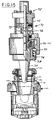
- a plunger carrier 32 supports a plunger cylinder 33 which includes a plunger 34 mounted on a piston 35.
- the plunger carrier 32 moves the plunger cylinder 33 over the down into position on top of the neck ring 31 immediately after the gob of glass goes through the neck ring 31 (Fig. 3). While the plunger cylinder 33 is being lowered into position, the extended plunger 34 begins to press into the glass (Fig. 3).
- a retractable alignment and clamping sleeve 36 provides accurate alignment of a plunger 34 through the neck ring 31 and into the glass gob before the plunger cylinder 33 is completely seated on top of the neck ring 31 and also keeps the neck ring 31 from pressing open during the pressing cycle.
- the independently controlled plunger cylinder 33 moves piston 35 to press the plunger 34 deeper into the glass gob to complete its stroke and force the glass up into the neck ring 31 to form a parison 2 (Fig. 4).
- This process differs from the conventional press and blow process on an I.S. machine in that in the present method the glass moves only from the bottom of the blank mold 30 up to the neck ring 31 as contrasted to the conventional I.S. method where the glass moves from the bottom of the inverted blank up to a baffle end and then back down to the neck ring. Less movement of the glass in the present method allows the parison 2 to be formed more quickly with less pressing force and enables the method to make a better quality container.
- the plunger cylinder 33 retracts the plunger 34 and the plunger carrier 32 moves the plunger cylinder 33 up and out of the way (Fig. 5).
- the parison 2 is then moved over to a blow mold 39 at the blowing station simultaneously with the downward movement of the solid blank mold 30 (Fig. 5).
- the parison 2 is thus transferred in a vertical upright position unlike the inverted position of conventional processes. This allows the arc of movement of the parison to be smaller which reduces the centrifugal forces which swing the parison outward. Therefore, less time is needed for the parison to come to rest directly over the bottom plate of the blow mold before final blowing can start (Fig. 5).
- the loading of gob of glass directly through the neck ring 31 into a solid vertical blank 30 eliminates the need for a funnel mechanism to guide the glass. This saves motion time which may be added to blank time or used to speed up the cycle.
- the plunger carrier with one or more individually controlled plunger cylinders mounted thereon, depending on the number of glass articles to be formed simultaneously lowers into position on top of the neck ring 31 immediately after the gob of glass loads through the neck ring 31 into the solid blank mold 30.
- the pressing of glass within the solid blank mold 30 starts as the plunger carrier 32 is lowering the plunger cylinder 33 down into final aligned position.
- the plunger cylinder 33 has an extended retractable alignment and clamping sleeve 36 that allows early and accurate pressing without the rings being pressed open. When the plunger cylinder 33 is in its final position, it will force the plunger 34 further down into the solid blank for the final press of the parison.
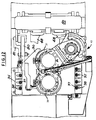
- FIG. 6 An apparatus embodying the invention for forming wide mouth glassware is shown in Fig. 6 which is basically an I.S. glass forming machine such as shown in US-A-3,024,571 and 3,233,999, incorporated herein by reference.
- the apparatus shown is a double gob machine but may be a single gob or plural gob machine including triple gob and quadruple gob as is well known in the art.
- Such an apparatus includes a section box 40 which supports the blank molds 30 at a blank or parison forming station 41 and the blow molds 30 at the blowing station 42.
- the apparatus includes a plunger cylinder and carrier moving assembly 43 at the blank forming station and a transfer assembly 44 associated with a neck ring holder and transfer arm assembly 45 which normally inverts the parisons, modified as presently described.
- a plunger cylinder and carrier moving assembly 43 at the blank forming station and a transfer assembly 44 associated with a neck ring holder and transfer arm assembly 45 which normally inverts the parisons, modified as presently described.
- Such an apparatus includes a blank cylinder assembly 46 on which the solid blank molds 30 are mounted for movement upwardly into receiving position of glass gobs from a feeder, not shown.
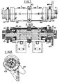
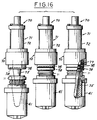
- the neck ring holder and transfer arm assembly 45 comprises openings 47a for a pair of neck rings 31 (Figs. 15, 16) supported in a neck ring holder 47 on neck ring arms 48.
- the arms 48 are each attached by their T-slot connections to T-slot bosses 49. These bosses 49 are each an integral part of the respective sleeves 50.
- the sleeves 50 are each internally splined and fit over complementary splines on enlarged central portions of an invert shaft 51.
- Each of the sleeves 50 is adapted for rotary motion with the shaft 51 and axial sliding movement along shaft 51, as presented described.
- the shaft 51 is rotatably mounted at its ends in bearings that are held in journals on the upright bracket of the support casting attached onto the underlying frame of the machine.
- the shaft 51 is rotatable to transfer the neck molds from the parison station 41 to the blow molding station 42, the latter station being displaced by approximately 180° of rotary movement of the arms 48 from the parison station.
- the sectional, partible blow molds (not shown) are mounted in a known manner on a pair of arms which are pivoted, in scissors fashion, on a vertical center pin.
- the pin is rigidly mounted on the machine frame by the support casting.
- These vertical shafts are herein shown to represent the blow mold position or station of the machine.
- the remainder of the blow mold mechanism, as well as the blank mold mechanism have been intentionally omitted from the drawings for the sake of simplicity of illustration of the invention.
- the rotation of the shaft 51 is accomplished by a pinion 53 that is rigidly secured by a key to the central part of shaft 51 and in meshing engagement with a vertically disposed rack 54a.
- the rack 54a is on the upper end of the piston rod 54 (Fig. 6) of a fluid pressure operated cylinder-piston motor 55.
- the reciprocating motion of rack 54a transmits a rotary motion to the pinion 53 which in turn rotates shaft 51.
- the neck ring arms 48 are moved in a rotary invert path by the splined connection between shaft 51 and the two carrier sleeves 50.
- the neck ring arms 48 are moved toward and away from each other for opening and closing the neck ring holders 47 and axially of the shaft by the sleeves 50 sliding along the splines on shaft 51.
- the opening motion is controlled by stops 52.
- This movement is accomplished by opposed, single-acting, fluid-pressure operated, cylyinder-piston assemblies 55 which function against springs.
- This apparatus for rotating is old and well known in I.S. machines as shown, for example in US-A-3,233,999, incorporated herein by reference.
- a crank arm 60 is provided on shaft 51 for rotation therewith.
- the apparatus 51 (Fig. 12) for moving the plunger carrier 32 toward and away from operating position is substantially like that in US-A-3,024,571, incorporated herein by reference, except that it is operated from above the blank molds rather than from below.
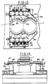
- the partible or split neck rings 31 are supported on a solid neck ring holder 47 which is pivoted intermediate to its ends on the arms 48.
- the neck ring arms 48 have pivot shafts 61 on the arms 48 that extend inwardly into recesses in the neck ring holders 47 (Fig. 10).
- the plunger carrier 70 carries two plunger assemblies 71, each of which comprises a cylinder 72 having a piston 73 with a rod 74 on which plunger 75 is mounted.
- a sleeve 76 is mounted on the lower end of the carrier 70 and is yieldingly urged downwardly by a spring 77.
- the lower end of the sleeve 76 is formed with an annular trapezoidal groove 78 which is adapted to engage a complementary annular bead 31a on the neck ring 31 to align the plunger and neck ring accurately.
- annular bead 31b on the bottom of the neck ring 31 to engage a complementary groove 30a on the blank mold 30 for alignment between neck ring and blank mold.
- the transfer apparatus comprises a transfer arm 80 pivoted at one end about a second fixed horizontal axis B spaced from the axis A of shaft 51 and pivoted at the other end to a neck ring arm 48 at axis C.
- a link 81 is pivotally connected at one end of crank 60 at axis D and at the other end to a point intermediate the ends of transfer arm 80 at axis E.
- Transfer arm 80 includes a short portion 80a and a long portion 80b at an obtuse angle to one another and the pivot axis E is at the juncture of the two portions.
- the radius of movement R1 of the pivot axis on crank 60 is the same as the radius R2 of the movement of pivot E about axis B; and the radius R3 of the movement of pivot axis F about axis A is the same as radius R4 of pivot axis C about axis B.
- the crank 60 and short portion 80a of the transfer arm 80 remain parallel, and the long portion 80b and the neck ring arm 48 remain parallel in all positions.
- Each plenum 90 includes a plurality of chambers 91, 92, 93, 94.
- the chambers 91-94 are supplied by adjustable plates 95 such that the amount of air to each chamber can be adjusted by varying the size of the inlet to each chamber from the air source 96.
- Each plate is held in adjusted position by a bolt 97 extending through a slot 98 in the plate 95 and into a threaded hole 99.
- Figs. 17-20 the apparatus is shown in various operating positions: The delivery of the gobs to the blank molds and the movement of the plunger carrier 70 into overlying relation to the blank molds (Fig. 17), the pressing of the glass (Fig. 18); the movement of the parisons toward the blow mold station (Fig. 19); and the positioning of the parisons to the blow mold station 42 for blowing (Fig. 20).
- Fig. 21 is a diagrammatic view showing how the transfer apparatus 44 having movement about two horizontal axes A, B maintains the parison in upright position.
Applications Claiming Priority (2)
| Application Number | Priority Date | Filing Date | Title |
|---|---|---|---|
| US08/281,718 US5588981A (en) | 1994-07-28 | 1994-07-28 | Apparatus for forming wide mouth glassware |
| US281718 | 1994-07-28 |
Publications (2)
| Publication Number | Publication Date |
|---|---|
| EP0694505A2 true EP0694505A2 (fr) | 1996-01-31 |
| EP0694505A3 EP0694505A3 (fr) | 1996-08-21 |
Family
ID=23078496
Family Applications (1)
| Application Number | Title | Priority Date | Filing Date |
|---|---|---|---|
| EP95111752A Withdrawn EP0694505A3 (fr) | 1994-07-28 | 1995-07-26 | Procédé et appareil pour la fabrication de verre creux à col large |
Country Status (17)
| Country | Link |
|---|---|
| US (2) | US5588981A (fr) |
| EP (1) | EP0694505A3 (fr) |
| JP (1) | JPH0891850A (fr) |
| KR (1) | KR960004241A (fr) |
| CN (1) | CN1137026A (fr) |
| AU (1) | AU2719095A (fr) |
| BR (1) | BR9503492A (fr) |
| CA (1) | CA2154946A1 (fr) |
| CO (1) | CO4440584A1 (fr) |
| CZ (1) | CZ191295A3 (fr) |
| EE (1) | EE9500041A (fr) |
| FI (1) | FI953524A (fr) |
| LT (1) | LT95090A (fr) |
| LV (1) | LV11313B (fr) |
| PE (1) | PE27475295A1 (fr) |
| PL (1) | PL309762A1 (fr) |
| ZA (1) | ZA956267B (fr) |
Cited By (2)
| Publication number | Priority date | Publication date | Assignee | Title |
|---|---|---|---|---|
| EP0831069A1 (fr) * | 1996-09-23 | 1998-03-25 | Owens-Brockway Glass Container Inc. | Procédé et appareil pour la fabrication d'objets creux en verre à col large |
| CN104193149A (zh) * | 2014-08-26 | 2014-12-10 | 德清才府玻璃股份有限公司 | 一种口模 |
Families Citing this family (11)
| Publication number | Priority date | Publication date | Assignee | Title |
|---|---|---|---|---|
| FR2770510B1 (fr) * | 1997-11-06 | 2000-03-31 | Emhart Glass Sa | Mecanisme d'ouverture et de fermeture de moule pour une machine a former a sections individuelles |
| DE10144112A1 (de) * | 2001-09-08 | 2003-03-27 | Hermann Heye I I | Verfahren und Fertigformstation zum Fertigblasen eines Glasbehälters |
| US7073352B2 (en) * | 2002-03-07 | 2006-07-11 | Vitro Global, S.A. | Method and a machine for the production of hollow glassware articles |
| US7185515B2 (en) * | 2003-06-27 | 2007-03-06 | Owens-Brockway Glass Container Inc. | Invert arm assembly for glassware forming machine |
| TWI245747B (en) * | 2004-07-30 | 2005-12-21 | Asia Optical Co Inc | Glass molding forming device capable of positioning glass material, supporting lens |
| CN102211852B (zh) * | 2011-04-19 | 2013-01-02 | 山东三金玻璃机械股份有限公司 | 一种伺服驱动平行开关 |
| CN102408185B (zh) * | 2011-07-26 | 2013-09-25 | 凤阳县龙兴玻璃有限公司 | 一种带把冷水壶一次成型模具 |
| USD754911S1 (en) | 2015-03-05 | 2016-04-26 | Bocci Design and Manufacturing Inc | Glass pendant for decorative light fixtures |
| US20180237324A1 (en) * | 2017-02-13 | 2018-08-23 | Keith Covert | Modular alignment process system for mold components |
| CN112851084A (zh) * | 2021-03-25 | 2021-05-28 | 重庆健力玻璃制品有限公司 | 机制爵口玻璃器皿及其制备方法 |
| CN113121088B (zh) * | 2021-04-20 | 2022-07-15 | 重庆星源玻璃器皿有限责任公司 | 玻璃制品吹制设备 |
Citations (5)
| Publication number | Priority date | Publication date | Assignee | Title |
|---|---|---|---|---|
| US1911119A (en) | 1928-05-04 | 1933-05-23 | Hartford Empire Co | Glassware forming machine |
| US2289046A (en) | 1939-07-19 | 1942-07-07 | Hartford Empire Co | Method of and apparatus for forming glassware |
| US3024571A (en) | 1957-07-25 | 1962-03-13 | Owens Illinois Glass Co | Apparatus for molding glass |
| US3233999A (en) | 1962-09-05 | 1966-02-08 | Owens Illinois Glass Co | Invert mechanism on glass forming machine |
| US4004906A (en) | 1975-01-31 | 1977-01-25 | Emhart Industries, Inc. | Glassware forming machine of the I. S. type for upright press and blow process |
Family Cites Families (30)
| Publication number | Priority date | Publication date | Assignee | Title |
|---|---|---|---|---|
| US1259281A (en) * | 1915-07-03 | 1918-03-12 | Hartford Fairmont Co | Manufacture of glassware. |
| US1618747A (en) * | 1926-03-04 | 1927-02-22 | Edward E Bartlett | Making blown-glass articles |
| US1781565A (en) * | 1928-03-13 | 1930-11-11 | Fed Glass Company | Method and apparatus for making articles of glassware |
| US1876005A (en) * | 1930-01-09 | 1932-09-06 | Owensillinois Glass Company | Glassware forming machine |
| US1888318A (en) * | 1930-05-08 | 1932-11-22 | Owens Illinois Glass Co | Mechanism for forming hollow glass articles |
| US1981692A (en) * | 1932-04-27 | 1934-11-20 | Dichter Jakob | Feeding means for glass tube manipulating machines |
| US2688823A (en) * | 1950-11-20 | 1954-09-14 | Owens Illinois Glass Co | Method and apparatus for forming glass parisons |
| US3147105A (en) * | 1957-07-25 | 1964-09-01 | Owens Illinois Glass Co | Apparatus for molding glass |
| US3241941A (en) * | 1957-07-25 | 1966-03-22 | Owens Illinois Glass Co | Neck mold apparatus for glass forming machine |
| NL231039A (fr) * | 1957-09-05 | |||
| US3198617A (en) * | 1959-10-08 | 1965-08-03 | Owens Illinois Glass Co | Mechanism for pressing charges of molten glass in a forming mold |
| US3329492A (en) * | 1964-02-12 | 1967-07-04 | Glass Machinery Inc | Apparatus for forming hollow glassware |
| US3434820A (en) * | 1965-02-03 | 1969-03-25 | Anthony T Zappia | Hollow glassware forming machine |
| US3490891A (en) * | 1966-10-03 | 1970-01-20 | Anchor Hocking Glass Corp | Multicluster blow molding machine |
| US3803877A (en) * | 1968-03-26 | 1974-04-16 | Heye H | Press and blow machine for the production of containers |
| US3580712A (en) * | 1969-02-10 | 1971-05-25 | Owens Illinois Inc | Glass forming mold elements with yielding supports |
| US3617233A (en) * | 1969-05-08 | 1971-11-02 | Owens Illinois Inc | Glass-forming machine |
| US3623856A (en) * | 1970-02-02 | 1971-11-30 | Owens Illinois Inc | Mold spray apparatus |
| US3672860A (en) * | 1970-08-19 | 1972-06-27 | Owens Illinois Inc | Glass gob shaping and delivering means |
| US3846103A (en) * | 1971-04-02 | 1974-11-05 | Emhart Corp | Method for making glassware by a press and blow technique |
| US3721542A (en) * | 1971-07-15 | 1973-03-20 | Owens Illinois Inc | Funnel arm mounted mold lubrication apparatus |
| US3732088A (en) * | 1971-08-30 | 1973-05-08 | A Zappia | Blow head assembly |
| GB1599803A (en) * | 1978-04-10 | 1981-10-07 | Emhart Ind | Glassware forming machines |
| DE2913358C2 (de) * | 1978-04-10 | 1983-03-31 | Emhart Industries Inc., Farmington, Conn. | Verfahren und Vorrichtung zum Herstellen von Glashohlkörpern |
| GB1601878A (en) * | 1978-05-24 | 1981-11-04 | Emhart Ind | Transfer means of glassware forming machines |
| US4274859A (en) * | 1980-02-19 | 1981-06-23 | Owens-Illinois, Inc. | Plunger operating mechanism for a glass forming machine |
| GB2166132B (en) * | 1984-10-27 | 1988-02-10 | Emhart Ind | Parison transferring mechanism |
| US4680050A (en) * | 1986-05-16 | 1987-07-14 | Ball Corporation | Glassware molding machine with unitary axis molding and method of molding glassware |
| US4830653A (en) * | 1987-08-18 | 1989-05-16 | Vitrocrisa Cristaleria, S.A. | Glass articles or similar materials transfer mechanism |
| GB9124211D0 (en) * | 1991-11-14 | 1992-01-08 | Emhart Glass Mach Invest | Takeout mechanism |
-
1994
- 1994-07-28 US US08/281,718 patent/US5588981A/en not_active Expired - Fee Related
-
1995
- 1995-07-21 FI FI953524A patent/FI953524A/fi not_active Application Discontinuation
- 1995-07-24 CZ CZ951912A patent/CZ191295A3/cs unknown
- 1995-07-25 PL PL95309762A patent/PL309762A1/xx unknown
- 1995-07-26 PE PE1995274752A patent/PE27475295A1/es not_active Application Discontinuation
- 1995-07-26 AU AU27190/95A patent/AU2719095A/en not_active Abandoned
- 1995-07-26 EP EP95111752A patent/EP0694505A3/fr not_active Withdrawn
- 1995-07-27 JP JP7191787A patent/JPH0891850A/ja active Pending
- 1995-07-27 LV LVP-95-233A patent/LV11313B/en unknown
- 1995-07-27 KR KR1019950022547A patent/KR960004241A/ko not_active Application Discontinuation
- 1995-07-27 CN CN95115052A patent/CN1137026A/zh active Pending
- 1995-07-27 CO CO95033431A patent/CO4440584A1/es unknown
- 1995-07-27 ZA ZA956267A patent/ZA956267B/xx unknown
- 1995-07-28 CA CA002154946A patent/CA2154946A1/fr not_active Abandoned
- 1995-07-28 EE EE9500041A patent/EE9500041A/xx unknown
- 1995-07-28 BR BR9503492A patent/BR9503492A/pt not_active Application Discontinuation
- 1995-07-28 LT LT95-090A patent/LT95090A/lt unknown
-
1996
- 1996-11-18 US US08/751,495 patent/US5690714A/en not_active Expired - Fee Related
Patent Citations (5)
| Publication number | Priority date | Publication date | Assignee | Title |
|---|---|---|---|---|
| US1911119A (en) | 1928-05-04 | 1933-05-23 | Hartford Empire Co | Glassware forming machine |
| US2289046A (en) | 1939-07-19 | 1942-07-07 | Hartford Empire Co | Method of and apparatus for forming glassware |
| US3024571A (en) | 1957-07-25 | 1962-03-13 | Owens Illinois Glass Co | Apparatus for molding glass |
| US3233999A (en) | 1962-09-05 | 1966-02-08 | Owens Illinois Glass Co | Invert mechanism on glass forming machine |
| US4004906A (en) | 1975-01-31 | 1977-01-25 | Emhart Industries, Inc. | Glassware forming machine of the I. S. type for upright press and blow process |
Cited By (3)
| Publication number | Priority date | Publication date | Assignee | Title |
|---|---|---|---|---|
| EP0831069A1 (fr) * | 1996-09-23 | 1998-03-25 | Owens-Brockway Glass Container Inc. | Procédé et appareil pour la fabrication d'objets creux en verre à col large |
| AU716945B2 (en) * | 1996-09-23 | 2000-03-09 | Owens-Brockway Glass Container Inc. | Method and apparatus for making wide mouth hollow glass articles |
| CN104193149A (zh) * | 2014-08-26 | 2014-12-10 | 德清才府玻璃股份有限公司 | 一种口模 |
Also Published As
| Publication number | Publication date |
|---|---|
| CO4440584A1 (es) | 1997-05-07 |
| CN1137026A (zh) | 1996-12-04 |
| KR960004241A (ko) | 1996-02-23 |
| FI953524A0 (fi) | 1995-07-21 |
| CA2154946A1 (fr) | 1996-01-29 |
| BR9503492A (pt) | 1997-05-27 |
| AU2719095A (en) | 1996-02-08 |
| LV11313B (en) | 1997-02-20 |
| LV11313A (lv) | 1996-06-20 |
| US5690714A (en) | 1997-11-25 |
| JPH0891850A (ja) | 1996-04-09 |
| US5588981A (en) | 1996-12-31 |
| EP0694505A3 (fr) | 1996-08-21 |
| CZ191295A3 (en) | 1996-06-12 |
| LT95090A (en) | 1996-02-26 |
| PE27475295A1 (es) | 1997-06-12 |
| ZA956267B (en) | 1996-03-13 |
| EE9500041A (et) | 1996-02-15 |
| FI953524A (fi) | 1996-01-29 |
| PL309762A1 (en) | 1996-02-05 |
Similar Documents
| Publication | Publication Date | Title |
|---|---|---|
| US4009018A (en) | Glassware forming machine of the I. S. type with in-line mold motion | |
| US2702444A (en) | Apparatus for forming glassware | |
| US5588981A (en) | Apparatus for forming wide mouth glassware | |
| RU2307077C2 (ru) | Способ и машина для производства полых стеклянных изделий | |
| US3914120A (en) | Individual section high speed glassware forming machine | |
| CN110546111B (zh) | 用于形成玻璃物品的机器的取出机构 | |
| US4449996A (en) | Parallel motion blank mold operating mechanism | |
| US4004906A (en) | Glassware forming machine of the I. S. type for upright press and blow process | |
| US4009016A (en) | Method of making glassware with a high speed press and blow technique | |
| US4466821A (en) | Baffle moving and alignment means for the four gob glass forming machine | |
| US5306325A (en) | Mold clamping mechanism for glass container forming machine | |
| US4002454A (en) | Glassware forming machine of the I. S. type for upright press and blow process | |
| US4152132A (en) | Method of forming glassware in a sector of a circle | |
| EP0210748B1 (fr) | Mécanisme de mouvement pour utilisation dans une machine de fabrication d'objets en verre du type à sections individuelles | |
| EP0705796B1 (fr) | Améliorations pour la fabrication de conteneurs en verre | |
| EP0708059B1 (fr) | Améliorations pour la fabrication de conteneurs en verre | |
| US3142553A (en) | Gob chute actuating mechanism | |
| US2984047A (en) | Apparatus for transferring and molding charges of molten glass | |
| US4063918A (en) | Apparatus for forming glassware with arc movements between molds | |
| GB2301585A (en) | Individual section glass blowing machine with moving dead-plate | |
| EP0245800B1 (fr) | Procédé et dispositif pour le moulage d'objets en verre sur un axe | |
| EP1670727B1 (fr) | Machine a presse-souffle pour la fabrication de verre creux | |
| JPH0137335B2 (fr) | ||
| US3477841A (en) | Mold support for glassware forming machine | |
| CN1154685A (zh) | 玻璃制品的成型 |
Legal Events
| Date | Code | Title | Description |
|---|---|---|---|
| PUAI | Public reference made under article 153(3) epc to a published international application that has entered the european phase |
Free format text: ORIGINAL CODE: 0009012 |
|
| AK | Designated contracting states |
Kind code of ref document: A2 Designated state(s): AT BE CH DE DK ES FR GB GR IE IT LI NL PT SE |
|
| PUAL | Search report despatched |
Free format text: ORIGINAL CODE: 0009013 |
|
| AK | Designated contracting states |
Kind code of ref document: A3 Designated state(s): AT BE CH DE DK ES FR GB GR IE IT LI NL PT SE |
|
| STAA | Information on the status of an ep patent application or granted ep patent |
Free format text: STATUS: THE APPLICATION IS DEEMED TO BE WITHDRAWN |
|
| 18D | Application deemed to be withdrawn |
Effective date: 19970222 |