EP0694325A1 - Column for contacting gas and liquid - Google Patents
Column for contacting gas and liquid Download PDFInfo
- Publication number
- EP0694325A1 EP0694325A1 EP94202213A EP94202213A EP0694325A1 EP 0694325 A1 EP0694325 A1 EP 0694325A1 EP 94202213 A EP94202213 A EP 94202213A EP 94202213 A EP94202213 A EP 94202213A EP 0694325 A1 EP0694325 A1 EP 0694325A1
- Authority
- EP
- European Patent Office
- Prior art keywords
- gas
- liquid
- section
- column
- contact
- Prior art date
- Legal status (The legal status is an assumption and is not a legal conclusion. Google has not performed a legal analysis and makes no representation as to the accuracy of the status listed.)
- Withdrawn
Links
Images
Classifications
-
- B—PERFORMING OPERATIONS; TRANSPORTING
- B01—PHYSICAL OR CHEMICAL PROCESSES OR APPARATUS IN GENERAL
- B01D—SEPARATION
- B01D3/00—Distillation or related exchange processes in which liquids are contacted with gaseous media, e.g. stripping
- B01D3/14—Fractional distillation or use of a fractionation or rectification column
- B01D3/16—Fractionating columns in which vapour bubbles through liquid
- B01D3/18—Fractionating columns in which vapour bubbles through liquid with horizontal bubble plates
- B01D3/20—Bubble caps; Risers for vapour; Discharge pipes for liquid
Definitions
- the present invention relates to a column for contacting upwardly flowing gas with downwardly flowing liquid in order to transfer mass, heat and momentum between the phases.
- Such columns for contacting gas and liquid are well known, and they are used in for example distillation, rectification, absorption and stripping.
- gas in the specification no distinction is made between gas and vapour; the word gas' also refers to vapour.
- a column for contacting upwardly flowing gas with downwardly flowing liquid is normally provided with an inlet for gas arranged in the lower part of the column, an inlet for liquid arranged in the upper part of the column, an outlet for liquid arranged in the lower end part of the column and an outlet for gas arranged in the upper end part of the column.
- the column can be provided with more inlets for liquid and gas and with more outlets for liquid, the number of these inlets and outlets and their locations depend on the application.
- the column there is arranged at least one horizontal tray upon which, during normal operation, liquid and gas are brought into contact with each other.
- a horizontal tray is a perforated plate provided with a downcomer.
- the present invention relates in particular to a column for contacting gas and liquid, wherein the horizontal tray comprises a plate provided with a tubular gas/liquid contact device.
- the tubular gas/liquid contact device comprises a contact section located below the plate, a separation section above the contact section, and an outlet section above the separation section and located above the plate, wherein the contact section is closed at its bottom, wherein the wall of the contact section is provided with a plurality of tangential gas inlets, wherein a liquid delivery tube opens into the lower end of the contact section, and wherein the outlet section has a gas permeable wall provided with coalescer means.
- the gas permeable wall provided with coalescer means comprises an open-ended tube having a cylindrical wall provided with tangential outlets, and a U-shaped annular deflector arranged over the upper end of the open ended tube, which annular deflector has a skirt extending over the tangential outlets for collecting liquid. So that, during normal operation, part of the upwardly flowing gas is deflected and liquid entrained in the gas is separated from the gas.
- the column for contacting upwardly flowing gas with downwardly flowing liquid is characterized in that the top of the outlet section is provided with a cover.
- the cover closes the upper end of the outlet section and thus the cover deflects during normal operation the upwardly passing fluid so that the fluid flows through the gas permeable wall provided with coalescer means.
- the liquid delivery tube delivers liquid into the lower part of the contact section of the tubular gas/liquid contact device.
- the liquid can come from the horizontal tray to which the tubular gas/liquid contact device pertains, and in this case inlet openings are made in the wall of the tubular gas/liquid contact device above the horizontal tray, and the liquid delivery tube is connected by means of supply conduits to the openings.
- the liquid may as well come from the horizontal tray above it, and in this case the liquid delivery tube is a downcomer tube extending downwards through the tubular gas/liquid contact device.
- the gas permeable wall provided with coalescer means of the outlet section comprises a tubular layer of coalescer material, wherein the inner diameter of the tubular layer is equal to or larger than the outer diameter of the separation section.
- the size of the inner diameter of the tubular layer is so selected that liquid collected in the tubular layer of coalescer material to can trickle into the space outside the tubular gas/liquid contact device and onto the plate.
- the net free area of the tubular layer of coalescer material is larger than or equal to between 1 and 1.5 times the cross-sectional area of the tubular gas/liquid contact device.
- the coalescer material includes a layer of expanded metal, which is a sheet of metal that is slit and stretched into a lattice. More suitably the coalescer material comprises at least two concentric layers of expanded metal.
- the outlet section further comprises two or more coalescer strips arranged at regular intervals along the outer surface of the gas permeable wall provided with coalescer means.
- the contact section is provided with several tangential gas inlets which are arranged at regular intervals along the circumference of the contact section.
- Each tangential gas inlet comprises an elongated strip bend to the inside of the contact section, the height of the strip being substantially equal to the height of the contact section.
- Upwardly flowing gas entering into the contact section is deflected, and the velocity of the gas in the contact section has a component in axial direction and a component in circumferential direction.
- the magnitude of the velocity in axial direction determines the time during which gas and liquid are in contact which each other, and it will be understood that the contact time is inverse proportional to the magnitude of the velocity in axial direction.
- each tangential gas inlet comprises a tongue which is bend to the inside of the contact section, the height of the tongue being small compared to the height of the contact section, and the tangential gas inlets are arranged one above the other in a column.
- the length of the tongue is suitably less than 10 percent of the length of the contact section.
- the contact section is provided with two or more of such columns of tangential gas inlets, which columns are arranged at regular intervals along the circumference of the contact section.
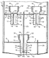
- the column 1 for contacting upwardly flowing gas with downwardly flowing liquid is provided with an inlet (not shown) for gas arranged in the lower part of the column 1, an inlet (not shown) for liquid arranged in the upper part of the column 1, an outlet (not shown) for liquid arranged in the lower end part of the column 1 and an outlet (not shown) for gas arranged in the upper end part of the column 1.
- the horizontal trays 3 and 5 are located between the lowermost inlet for gas and the outlet for gas.
- the upper horizontal tray 3 comprises a horizontal plate 6 provided with two vertical tubular gas/liquid contact devices 8 extending through openings in the plate 6, and the lower horizontal tray 5 comprises a horizontal plate 7 provided with one vertical tubular gas/liquid contact device 10 extending through an opening in the plate 7.
- Each of the tubular gas/liquid contact devices 8 and 10 comprises a contact section 12, a separation section 13 which is arranged above the contact section 12, and an outlet section 15 which is arranged above the separation section 13.
- the contact sections 12 of the tubular gas/liquid contact devices 8 are located below the plate 6 and the outlet sections 15 are located above the plate 6, and the contact section 12 of the tubular gas/liquid contact device 10 is located below the plate 7 and the outlet section 15 above the plate 7.
- the contact section 12, the separation section 13 and the outlet section 15 are in fluid communication with each other.
- the wall of the contact section 12 is provided with a plurality of tangential gas inlets 16, for the sake of clarity not all tangential gas inlets are referred to with a reference numeral.
- Each tangential gas inlet 16 comprises a tongue which is bend to the inside of the contact section 12, the height of the tongue being small compared to the height of the contact section 12, and the tangential gas inlets 16 are arranged one above the other in a column 17.
- the tongues have not been referred to with a reference numeral.
- the contact section 12 is closed at its lower end by means of a cover 18.
- a liquid delivery tube 19 opens into the lower end of the contact section 12.
- the liquid delivery tubes 19 of the tubular gas/liquid contact devices 8 are connected to supply conduits 20, which have inlet openings 21 opening above the plate 6.
- the liquid delivery tube 19 of the tubular gas/liquid contact device 10 is a downcomer tube 23 which extends through an opening in the plate 6 from the next higher tray 3 downwards through the tubular gas/liquid contact device 10, which downcomer 23 has an inlet opening 24 which is located above inlet openings 21.
- the outlet section 15 comprises a gas permeable wall provided with coalescer means 25.
- the top of the outlet section 15 is provided with a cover 27.
- the gas permeable wall provided with coalescer means 25 comprise a tubular layer of coalescer means in the form of two concentric layers of expanded metal 30, the inner diameter of the tubular layer of coalescer means is equal to or greater than the outer diameter of the separation section 13 so that the tubular layer fits over the separation section 13.
- the outlet section 15 further comprises two coalescer strips 32 arranged at regular intervals along the outer surface of the gas permeable wall provided with coalescer means 25.
- liquid is continuously supplied to the inlet (not shown) for liquid arranged in the upper part of the column 1, and gas is continuously supplied to the inlet (not shown) for gas arranged in the lower part of the column 1.
- Liquid supplied to the upper end of column 1 is collected on plate 6 of the upper horizontal tray 3. Part of the liquid flows through inlet openings 21 into the liquid delivery tubes 19, another part of the liquid flows through inlet opening 24 and downcomer tube 23 into the lower end of the contact section 12 of the tubular gas/liquid contact device 10, and the remainder of the liquid remains on the plate 6. Upwardly flowing gas enters through the tangential gas inlets 16 into the contact sections 12 of the tubular gas/liquid contact devices 8.
- Liquid entering into the contact sections 12 is dispersed by the swirling gas, and in dispersed form liquid is contacted with gas.
- the swirling fluid enters into the separation sections 13 of the tubular gas/liquid contact devices 8.
- liquid moves outwards under the influence of centrifugal forces and it is collected on the inner surfaces of the walls of the separation sections 13.
- Gas and liquid enter into the outlet sections 15, and leave the outlet sections 15 of the tubular gas/liquid contact devices 8 through coalescer means in the form of the two concentric layers of expanded metal 30. Liquid is collected on the coalescer means and trickles downwards on the plate 6, and gas flows upwards.
- the outlet sections 8 are provided with coalescer strips 32 which improve the separation, and reduce the entrainment of liquid in the gas.
- the cover 27 deflects the upwardly flowing fluid so that it flows through the coalescer means.
- Liquid flowing through the downcomer tube 23 is passed to the lower end of the tubular gas/liquid contact device 10 pertaining to the lower horizontal tray 5.
- gas and liquid are brought in contact with each other in the same way as described above with reference to the tubular gas/liquid contact devices 8.
- Liquid leaving the outlet section 15 of the tubular gas/liquid contact device 10 is collected on the plate 7 of the lower horizontal tray 5, and excess liquid is removed from the lower horizontal tray 5 through downcomer tube 35 extending through an opening the plate 7.
- downcomer tube 35 opens into tubular gas/liquid contact device (not shown) of that further horizontal tray; and in case the lower horizontal tray 5 is the lowermost horizontal tray, liquid is discharged into the lower end of the column 1 from which it is withdrawn through the outlet for liquid (not shown).
- the entrainment is the volume of liquid entrained per unit of time divided by the volume of liquid supplied to the column per unit time
- the gas load factor is the volume of gas supplied to the contact device per unit time divided by the area of the gas/liquid contacting device times the square root of the ratio of the gas density over the liquid density minus the gas density.
- the lower end of the contact section 12 of the tubular gas/liquid contact device 10, under the lowermost tangential gas inlet 16 is provided with a vortex breaker in the form of a vertical flat plate 38 arranged on the cover 18, the lower end of the liquid delivery tube 19 rests in recess 40 in the upper edge of the flat plate 38.
- the vortex breaker may as well include two flat plates, wherein one flat plate is in the plane of drawing (like flat plate 38), and wherein the second flat plate (not shown) is perpendicular to the plane of drawing.
- the outlet section 25 can comprise more than the two coalescer strips 32 which are shown in the drawing, for example between 3 and 5, all coalescer strips are suitably arranged at regular intervals along the outer surface of the gas permeable wall provided with coalescer means 25.
- the cross-section of the tubular gas/liquid contact device as discussed with reference to the drawing is circular, however, the cross-section can be polygonal as well.
- the lower end of the liquid delivery tube 19 is arranged under the lowermost tangential gas inlet 16, so that, during normal operation, liquid present in the lower end of each of the tubular gas/liquid contact devices 8 and 10 seals the liquid delivery tube 19.
- the wall of each contact tube is provided with a small aperture (not shown) arranged above the plate of the horizontal tray to which the contact tube pertains and below the inlet opening 24 of the downcomer tube 23.
- the cover 18 at the bottom of the contact section 12 is provided with a small aperture (not shown). The size of the apertures in the wall and in the cover is so selected that the presence of the apertures does not adversely affect the separation performance of the tubular gas/liquid contact device.
Landscapes
- Chemical & Material Sciences (AREA)
- Chemical Kinetics & Catalysis (AREA)
- Vaporization, Distillation, Condensation, Sublimation, And Cold Traps (AREA)
- Gas Separation By Absorption (AREA)
Priority Applications (15)
| Application Number | Priority Date | Filing Date | Title |
|---|---|---|---|
| EP94202213A EP0694325A1 (en) | 1994-07-29 | 1994-07-29 | Column for contacting gas and liquid |
| EP95928495A EP0772483B1 (en) | 1994-07-29 | 1995-07-27 | Column for contacting gas and liquid |
| PCT/EP1995/003033 WO1996004056A1 (en) | 1994-07-29 | 1995-07-27 | Column for contacting gas and liquid |
| CZ1997261A CZ288644B6 (cs) | 1994-07-29 | 1995-07-27 | Kolona pro uvádění vzhůru stoupajícího plynu a dolů stékající kapaliny do vzájemného styku |
| CA002196067A CA2196067C (en) | 1994-07-29 | 1995-07-27 | Column for contacting gas and liquid |
| NZ291180A NZ291180A (en) | 1994-07-29 | 1995-07-27 | Gas/liquid contacting column designed for reduced entrainment of liquid |
| CN95194398A CN1045544C (zh) | 1994-07-29 | 1995-07-27 | 气液接触塔 |
| AU32235/95A AU686441B2 (en) | 1994-07-29 | 1995-07-27 | Column for contacting gas and liquid |
| DE69515877T DE69515877T2 (de) | 1994-07-29 | 1995-07-27 | Kolonne zum kontaktieren von gas und flüssigkeit |
| BR9508438A BR9508438A (pt) | 1994-07-29 | 1995-07-27 | Coluna para provocar contato entre gás e líquido |
| DK95928495T DK0772483T3 (da) | 1994-07-29 | 1995-07-27 | Kolonne til at bringe gas og væske i kontakt med hinanden |
| PL95318349A PL179882B1 (pl) | 1994-07-29 | 1995-07-27 | Kolumna do kontaktowania gazu i cieczy PL PL |
| JP50619196A JP3877225B2 (ja) | 1994-07-29 | 1995-07-27 | 気体と液体を接触させるカラム |
| US08/555,060 US5690708A (en) | 1994-07-29 | 1995-11-08 | Column for contacting gas and liquid |
| NO19970345A NO314442B1 (no) | 1994-07-29 | 1997-01-27 | Kolonne for å bringe gass og v¶ske i kontakt |
Applications Claiming Priority (2)
| Application Number | Priority Date | Filing Date | Title |
|---|---|---|---|
| EP94202213A EP0694325A1 (en) | 1994-07-29 | 1994-07-29 | Column for contacting gas and liquid |
| US08/555,060 US5690708A (en) | 1994-07-29 | 1995-11-08 | Column for contacting gas and liquid |
Publications (1)
| Publication Number | Publication Date |
|---|---|
| EP0694325A1 true EP0694325A1 (en) | 1996-01-31 |
Family
ID=26136465
Family Applications (2)
| Application Number | Title | Priority Date | Filing Date |
|---|---|---|---|
| EP94202213A Withdrawn EP0694325A1 (en) | 1994-07-29 | 1994-07-29 | Column for contacting gas and liquid |
| EP95928495A Expired - Lifetime EP0772483B1 (en) | 1994-07-29 | 1995-07-27 | Column for contacting gas and liquid |
Family Applications After (1)
| Application Number | Title | Priority Date | Filing Date |
|---|---|---|---|
| EP95928495A Expired - Lifetime EP0772483B1 (en) | 1994-07-29 | 1995-07-27 | Column for contacting gas and liquid |
Country Status (6)
| Country | Link |
|---|---|
| US (1) | US5690708A (no) |
| EP (2) | EP0694325A1 (no) |
| CA (1) | CA2196067C (no) |
| NO (1) | NO314442B1 (no) |
| PL (1) | PL179882B1 (no) |
| WO (1) | WO1996004056A1 (no) |
Cited By (3)
| Publication number | Priority date | Publication date | Assignee | Title |
|---|---|---|---|---|
| EP0975404A1 (en) * | 1997-04-07 | 2000-02-02 | Mobil Oil Corporation | Co-current contacting separation tray design and methods for using same |
| WO2001060481A2 (en) * | 2000-02-16 | 2001-08-23 | Shell Internationale Research Maatschappij B.V. | Column for counter-currently contacting gas and liquid |
| ITMI20111299A1 (it) * | 2011-07-12 | 2013-01-13 | Saipem Spa | Piatto di reattore per la produzione di urea, e reattore e processo di produzione di urea |
Families Citing this family (12)
| Publication number | Priority date | Publication date | Assignee | Title |
|---|---|---|---|---|
| NZ282814A (en) * | 1994-03-24 | 1997-07-27 | Shell Int Research | Column with horizontal contact trays and overlying separation trays having swirl tubes and annular deflectors |
| DE59707105D1 (de) * | 1997-06-05 | 2002-05-29 | Sulzer Chemtech Ag Winterthur | Ablaufschacht zu einer Bodenkolonne |
| US6460834B2 (en) * | 2000-02-16 | 2002-10-08 | Shell Oil Company | Gas/liquid contact tray |
| US6682633B1 (en) | 2000-12-22 | 2004-01-27 | Uop Llc | Apparatus for cocurrent fractional distillation |
| RU2287359C2 (ru) * | 2004-11-30 | 2006-11-20 | Открытое акционерное общество "Минерально-химическая компания "ЕвроХим"(ОАО "МХК "ЕвроХим") | Вихревой аппарат для проведения физико-химических процессов с нисходящим потоком фаз |
| US7424999B2 (en) * | 2005-12-16 | 2008-09-16 | Uop Llc | Co-current vapor-liquid contacting apparatus |
| US7981201B2 (en) * | 2008-12-31 | 2011-07-19 | Uop Llc | De-entrainment device |
| US8608833B2 (en) | 2010-06-09 | 2013-12-17 | Uop Llc | Selective absorption of gas components in co-current contacting apparatuses |
| DE112012000436B4 (de) * | 2011-01-10 | 2015-10-08 | Koch-Glitsch, Lp | Kontaktboden, Kolonne mit Kontaktböden und Verfahren zum Betreiben einer Kolonne |
| RU2466767C2 (ru) * | 2011-03-30 | 2012-11-20 | Федеральное государственное бюджетное образовательное учреждение высшего профессионального образования "Сибирский государственный технологический университет" (СибГТУ) | Тепломассообменная вихревая колонна |
| DE102011119148A1 (de) * | 2011-11-22 | 2013-05-23 | Linde Ag | Kolonne |
| US11786855B2 (en) * | 2018-03-29 | 2023-10-17 | Uop Llc | Vapor-liquid contacting apparatus and process with downcomer at shell |
Citations (2)
| Publication number | Priority date | Publication date | Assignee | Title |
|---|---|---|---|---|
| GB1123546A (en) * | 1965-02-26 | 1968-08-14 | Shell Int Research | Tray for contacting liquids and gases |
| DE2141858A1 (en) * | 1970-08-21 | 1972-02-24 | Mitsui Shipbuilding And Engineering Co. Ltd., Tokio | Gas liquid contact column - with perforated plate in flow baffle at each level |
Family Cites Families (11)
| Publication number | Priority date | Publication date | Assignee | Title |
|---|---|---|---|---|
| US1651354A (en) * | 1925-05-09 | 1927-12-06 | Clive M Alexander | Baffle tower |
| US2042150A (en) * | 1930-12-01 | 1936-05-26 | Shell Dev | Apparatus for and process of fractionation |
| US1918005A (en) * | 1932-02-02 | 1933-07-11 | Kenneth M Urquhart | Bubble cap |
| US2055048A (en) * | 1932-06-30 | 1936-09-22 | Texas Co | Entrainment separator for fractionating towers |
| US2893713A (en) * | 1956-04-10 | 1959-07-07 | Bayer Ag | Bubble cap assembly |
| US3197286A (en) * | 1963-02-18 | 1965-07-27 | Hydrocarbon Research Inc | Liquid phase reactor |
| US3475134A (en) * | 1965-05-05 | 1969-10-28 | Hydrocarbon Research Inc | Liquid phase reactor |
| US3779525A (en) * | 1971-08-19 | 1973-12-18 | Mitsui Shipbuilding Eng | Gas-liquid contacting apparatus |
| US3864439A (en) * | 1971-12-21 | 1975-02-04 | Mitsui Shipbuilding Eng | Gas-liquid contacting apparatus |
| US4060399A (en) * | 1976-08-30 | 1977-11-29 | Gleason Thomas G | Scrubber-cooler tower |
| JP2640396B2 (ja) * | 1991-04-15 | 1997-08-13 | 三井造船株式会社 | 気液接触装置 |
-
1994
- 1994-07-29 EP EP94202213A patent/EP0694325A1/en not_active Withdrawn
-
1995
- 1995-07-27 EP EP95928495A patent/EP0772483B1/en not_active Expired - Lifetime
- 1995-07-27 CA CA002196067A patent/CA2196067C/en not_active Expired - Fee Related
- 1995-07-27 WO PCT/EP1995/003033 patent/WO1996004056A1/en active IP Right Grant
- 1995-07-27 PL PL95318349A patent/PL179882B1/pl unknown
- 1995-11-08 US US08/555,060 patent/US5690708A/en not_active Expired - Fee Related
-
1997
- 1997-01-27 NO NO19970345A patent/NO314442B1/no not_active IP Right Cessation
Patent Citations (2)
| Publication number | Priority date | Publication date | Assignee | Title |
|---|---|---|---|---|
| GB1123546A (en) * | 1965-02-26 | 1968-08-14 | Shell Int Research | Tray for contacting liquids and gases |
| DE2141858A1 (en) * | 1970-08-21 | 1972-02-24 | Mitsui Shipbuilding And Engineering Co. Ltd., Tokio | Gas liquid contact column - with perforated plate in flow baffle at each level |
Cited By (10)
| Publication number | Priority date | Publication date | Assignee | Title |
|---|---|---|---|---|
| EP0975404A1 (en) * | 1997-04-07 | 2000-02-02 | Mobil Oil Corporation | Co-current contacting separation tray design and methods for using same |
| EP0975404A4 (en) * | 1997-04-07 | 2000-05-03 | Mobil Oil Corp | MODEL OF CO-CURRENT SEPARATION AND CONTACT TRAY AND METHODS OF USE |
| WO2001060481A2 (en) * | 2000-02-16 | 2001-08-23 | Shell Internationale Research Maatschappij B.V. | Column for counter-currently contacting gas and liquid |
| WO2001060481A3 (en) * | 2000-02-16 | 2002-03-21 | Shell Int Research | Column for counter-currently contacting gas and liquid |
| ITMI20111299A1 (it) * | 2011-07-12 | 2013-01-13 | Saipem Spa | Piatto di reattore per la produzione di urea, e reattore e processo di produzione di urea |
| WO2013008147A3 (en) * | 2011-07-12 | 2013-04-11 | Saipem S.P.A. | Urea reactor tray, reactor, and production process |
| AU2012282191B2 (en) * | 2011-07-12 | 2015-06-25 | Saipem S.P.A. | Urea reactor tray, reactor, and production process |
| US9192902B2 (en) | 2011-07-12 | 2015-11-24 | Saipem S.P.A. | Urea reactor tray, reactor, and production process |
| EP2992940A1 (en) * | 2011-07-12 | 2016-03-09 | Saipem S.p.A. | Urea reactor tray, reactor, and production process |
| RU2606126C2 (ru) * | 2011-07-12 | 2017-01-10 | САИПЕМ С.п.А. | Тарелка реактора для получения мочевины, реактор и способ получения мочевины |
Also Published As
| Publication number | Publication date |
|---|---|
| NO970345L (no) | 1997-01-27 |
| NO970345D0 (no) | 1997-01-27 |
| CA2196067C (en) | 2006-10-17 |
| EP0772483B1 (en) | 2000-03-22 |
| CA2196067A1 (en) | 1996-02-15 |
| PL179882B1 (pl) | 2000-11-30 |
| PL318349A1 (en) | 1997-06-09 |
| NO314442B1 (no) | 2003-03-24 |
| EP0772483A1 (en) | 1997-05-14 |
| WO1996004056A1 (en) | 1996-02-15 |
| US5690708A (en) | 1997-11-25 |
Similar Documents
| Publication | Publication Date | Title |
|---|---|---|
| EP0772483B1 (en) | Column for contacting gas and liquid | |
| EP0048508B1 (en) | Apparatus for treating mixtures of liquid and gas | |
| JP3787153B2 (ja) | 気体と液体とを向流接触させる塔 | |
| US3492795A (en) | Separation of vapor fraction and liquid fraction from vapor-liquid mixture | |
| AU737526B2 (en) | Co-current contacting separation tray design and methods for using same | |
| US5112375A (en) | Radial vane demisting system in a separator for removing entrained droplets from a gas stream | |
| US3296774A (en) | Gas-liquid contactor with wall obstructions and contacting method | |
| JPS6316966B2 (no) | ||
| US4880451A (en) | Gas/liquid contacting apparatus | |
| US5300132A (en) | Contacting device | |
| WO2004073836A2 (en) | Separation tray | |
| US7004988B2 (en) | Gas-liquid separator | |
| AU686441B2 (en) | Column for contacting gas and liquid | |
| EP0083811B1 (en) | Apparatus for separating mixtures of liquid and gas | |
| US5320652A (en) | Steam separating apparatus | |
| US4588563A (en) | Cascade sieve tray for extraction and deasphalting | |
| US20010015136A1 (en) | Column for counter-currently contacting gas and liquid | |
| US6877725B2 (en) | Vapor/liquid contacting cyclone with secondary vanes | |
| EP1330297A1 (en) | Column for counter-currently contacting vapour and liquid | |
| EP1096992A1 (en) | Vapor/liquid contacting cyclone with devices to prevent backmixing | |
| US5275644A (en) | Steam separating apparatus | |
| US2772748A (en) | Contacting fluids with entrainment and inertia separation |
Legal Events
| Date | Code | Title | Description |
|---|---|---|---|
| PUAI | Public reference made under article 153(3) epc to a published international application that has entered the european phase |
Free format text: ORIGINAL CODE: 0009012 |
|
| AK | Designated contracting states |
Kind code of ref document: A1 Designated state(s): GB |
|
| STAA | Information on the status of an ep patent application or granted ep patent |
Free format text: STATUS: THE APPLICATION IS DEEMED TO BE WITHDRAWN |
|
| 18D | Application deemed to be withdrawn |
Effective date: 19960801 |