EP0694219B1 - Schnappverbinder für elektrische leitungen - Google Patents
Schnappverbinder für elektrische leitungen Download PDFInfo
- Publication number
- EP0694219B1 EP0694219B1 EP94914375A EP94914375A EP0694219B1 EP 0694219 B1 EP0694219 B1 EP 0694219B1 EP 94914375 A EP94914375 A EP 94914375A EP 94914375 A EP94914375 A EP 94914375A EP 0694219 B1 EP0694219 B1 EP 0694219B1
- Authority
- EP
- European Patent Office
- Prior art keywords
- clip
- connector according
- snap
- terminal block
- line
- Prior art date
- Legal status (The legal status is an assumption and is not a legal conclusion. Google has not performed a legal analysis and makes no representation as to the accuracy of the status listed.)
- Expired - Lifetime
Links
- 238000007789 sealing Methods 0.000 claims description 7
- 238000001746 injection moulding Methods 0.000 claims description 2
- 238000005266 casting Methods 0.000 claims 1
- 230000010287 polarization Effects 0.000 abstract 1
- 238000004382 potting Methods 0.000 description 7
- 150000001875 compounds Chemical class 0.000 description 5
- 238000009413 insulation Methods 0.000 description 5
- 230000007613 environmental effect Effects 0.000 description 2
- 239000007789 gas Substances 0.000 description 2
- 239000007788 liquid Substances 0.000 description 2
- 206010000496 acne Diseases 0.000 description 1
- 230000005540 biological transmission Effects 0.000 description 1
- 238000011161 development Methods 0.000 description 1
- 230000018109 developmental process Effects 0.000 description 1
- 238000006073 displacement reaction Methods 0.000 description 1
- 238000003780 insertion Methods 0.000 description 1
- 230000037431 insertion Effects 0.000 description 1
- 239000000463 material Substances 0.000 description 1
Images



Definitions
- the invention relates to a connector with a contacting device for contacting a polarity-protected, coded, electrical line.
- Contacting devices for making contact with a polarity-protected, coded electrical line are proposed in the as yet unpublished German patent application P 43 20 327.2. Contacting devices are used here for actuators or sensors. Knife contacts of the contacting device are pressed into the wire to make contact with the stranded wires. The knife contacts are in a housing wall of the actuator or sensor. The shape-coded line is held and positioned in a recess adapted to its shape coding in connection with snap hooks in a cover part that can be placed on the housing.
- a module for connecting actuators and / or sensors is disclosed, which allows a line to be contacted in a simple manner, inexpensively and reliably with a simple structure.
- a lower part housing is provided with a contacting device, which essentially consists of a guide part, a cable basket and band-shaped contacts with contact tips.
- the cable basket can be locked in two height positions in the guide part.
- the cable with a form coding can be inserted.
- the insulation of the cable is replaced by the contact tips pierce and at the same time contacted the line wires of the line.
- the invention has for its object to provide a connector with a contacting device for contacting a polarity-protected coded electrical line, which is simple and allows easy pre-assembly and disassembly of the electrical line. This is achieved by a connector according to the features of claim 1. Advantageous developments of the invention can be found in the subclaims.
- connection block is provided with a sealing rib running around the two contact tips, then a good seal of the contact point against liquids and gases is achieved in a simple manner when using a cable with soft insulation.
- connection block around the two contact tips, into which an O-ring can be inserted.
- the required sealing could be achieved using the O-ring.
- connection block has a potting hole, it can be used to fill an electrical device mounted on the bottom of the snap connector with potting compound.
- the potting compound protects the electronics from environmental influences and connects the snap connector to the electrical device.
- the snap connector can be used advantageously for further applications if a gating for an electrical device to be connected is attached to the outside of the base of the terminal block.
- connection block 2 shows a snap connector 1, which consists of a connection block 2 and a clip 3 which can be snapped thereon and which is provided with a contacting device for contacting with a polarity-proof coded electrical line 4.
- the connection block 2 and the bracket 3 are preferably designed as a plastic part.
- the snap connector 1 serves as a connecting part between the line 4 and an electrical device which can be fastened to the connection block 2.
- the line 4 has two parallel line wires and has an insulating jacket provided with a coding lug 5.
- the connection block 2 is U-shaped, that is to say it is formed with a central web, which is referred to as the base 6, and lateral legs 7.
- two contact tips 8 are arranged on the inside in such a way that there is space for a printed circuit board between them.
- the contact tips 8 are conical in shape and together they are surrounded by a closely surrounding sealing rib 9.
- a leading around the contact tips 8 and the sealing rib 9 circular ring groove 10 introduced, in which an O-ring can be inserted.
- the bottom 6 is provided with two different recesses 11 in addition to the two legs 7.
- a potting hole 12 leading through the bottom 6 lies within the area surrounded by the annular groove 10.
- the two legs 7 each have a guide groove 13 on the outside, which is formed here by projecting strips 14.
- the guide grooves 13 are each provided with a beveled snap hook 15 and have 7 bevels 16 at the ends of the legs.
- the clip 3 can be snapped onto the connection block 2 with its snap arms 17. It has a clamp bed 18 which serves to receive the form-coded line 4 and is therefore shaped to match the form coding.
- the clamp bed 18 is closed at the top with retaining hooks 19.
- the width of the two snap arms 17 is also adapted to the guide grooves 13 of the connection block 2. They have snap arm openings 20, into which the snap hooks 15 are engaged when the snap connector 1 is assembled.
- the clamp bed 18 is provided with coding lugs 21, which are designed differently in shape on both sides of the snap arms 17 and, with correct assembly, fit positively into the associated recesses 11 in the connection block 2.
- the clamp 3 has openings 22 with opening surfaces 23 tapering towards the snap hooks 15.
- the bracket 3 and the connection block 2 have visible grooves 24, through which the position required for the assembly of both plastic parts is ensured by correct assignment.
- the assembly of the line 4 with the snap connector 1 is carried out in the manner described below.
- the form-coded line 4 is pressed past the four holder hooks 19 into the clamp bed 18 of the clamp 3. In this way, the line 4 is prevented from falling out when snapping together with the terminal block 2.
- the lateral displacement of the clamp 3 on the line 4 is possible until the snap closure is finally closed.
- connection block 2 The position of the preassembled clamp 3 on the connection block 2 is fixed against rotation by the coding lugs 21.
- the contact tips 8 are contacted in a straight and precise manner with the line 4 by guiding the snap arms 17 in the guide grooves 13 on the end face on the connection block 2 and by guiding the aligned geometry of the coding lugs 21 on the clamp 3 with the connection block 2.
- the strips 14 on the connection block 2 also serve to protect the snap arms 17 during the connection. Sliding on the pretensioned snap arms 17 of the clamp 3 on the connection block 2 is facilitated by the insertion bevels 16.
- the snap arms 17 When assembling the plastic parts, the snap arms 17 are pressed apart by the bevels on the snap hooks 15 until both snap into the snap arm openings 20.
- the retaining hooks 19 and the coding lugs 21 sink into the provided recesses or recesses 11 and limit the snap path of the clip 3.
- the snap arms 17 are designed to be angled in order to achieve small clip dimensions with the selected material, with the required snap arm length and spring action.
- the molded on the terminal block 2 sealing rib 8 seals the contact point when using a cable 4 with softer elastic insulation, such as with a rubber compound (EPR), against liquids and gases. If a line 4 with harder insulation (eg PUR) is used, the contact point can be sealed with a suitable O-ring that is inserted into the circumferential ring groove 10 in the connection block 2.
- EPR rubber compound
- a strain relief of the line 4 is achieved by injection molding suitable shapes, e.g. Pimples and webs on the bottom 6 of the clamp bed 18 enable the line 4 to be squeezed when the snap connector 1 is closed.
- the fully assembled electrical device can be filled with potting compound through the potting hole 12.
- the potting compound protects the electronics from environmental influences and connects the snap connector 1 to the electrical device.
- the line 4 is disassembled by inserting a suitable tool, for example a screwdriver, into the openings 22 on the clamp 3.
- the tool is brought up to the snap arms 17 via the tapering opening surfaces 23, which can be unhooked with rotary or lever movements.
- the snap connection 1 is overall such that all movable, thin-walled and elastic parts are included in the bracket 3. If damaged, this part can easily be replaced.
- the terminal block 2, which is attached to the electrical device, is comparatively massive.
- a suitable gating for the electrical device to be connected can be individually attached to the bottom surface of the connection block 2 according to the requirements of the respective user.
- the line 4 can be a bus line, for example, which is used to provide electrical energy and / or for data transmission.
Landscapes
- Connector Housings Or Holding Contact Members (AREA)
- Details Of Connecting Devices For Male And Female Coupling (AREA)
Abstract
Description
- Die Erfindung bezieht sich auf einen Verbinder mit einer Kontaktierungseinrichtung zur Kontaktierung mit einer verpolungssicher formkodierten, elektrischen Leitung.
- Kontaktierungseinrichtungen zur Kontaktierung mit einer verpolungssicher formkodierten, elektrischen Leitung sind in der noch unveröffentlichten deutschen Patentanmeldung P 43 20 327.2 vorgeschlagen. Hier werden die Kontaktierungseinrichtungen bei Aktuatoren oder Sensoren eingesetzt. Messerkontakte der Kontaktierungeinrichtung werden zur Kontaktierung mit Schaltlitzen der Leitung in diese eingedrückt. Die Messerkontakte stecken in einer Gehäusewandung des Aktuators oder Sensors. Die formkodierte Leitung ist in einer ihrer Formkodierung angepaßten Ausnehmung in Verbindung mit Schnapphaken in einem auf das Gehäuse aufsetzbaren Deckelteil gehalten und positioniert.
- Eine weitere Anwendung von derartigen Kontaktierungseinrichtungen ist in der unveröffentlichten europäischen Patentanmeldung 93 106 060.2 vorgestellt. Hier ist ein Modul zum Anschluß von Aktoren und/oder Sensoren offenbart, das bei einfachem Aufbau die Kontaktierung einer Leitung auf einfache Weise, kostengünstig und zuverlässig ermöglicht. Hierzu ist ein Unterteil-Gehäuse mit einer Kontaktierungseinrichtung versehen, welche im wesentlichen aus einem Führungsteil, einem Leitungskorb und bandförmigen Kontakten mit Kontaktspitzen besteht. Der Leitungskorb ist in zwei Höhenstellungen im Führungsteil verrastbar. In den Leitungskorb ist in der oberen Vormontage-Stellung, die mit einer Formkodierung versehene Leitung einlegbar. Bei Verschiebung des Leitungskorbes in die untere Stellung wird die Isolierung der Leitung durch die Kontaktspitzen durchstoßen und zugleich Leitungsadern der Leitung kontaktiert.
- Der Erfindung liegt die Aufgabe zugrunde, einen Verbinder mit einer Kontaktierungseinrichtung zur Kontaktierung mit einer verpolungssicher formkodierten, elektrischen Leitung zu schaffen, der einfach aufgebaut ist und eine einfache Vormontage und Demontage der elektrischen Leitung ermöglicht. Dies wird erreicht durch einen Verbinder gemäß den Merkmalen nach Patentanspruch 1. Vorteilhafte Weiterbildungen der Erfindung sind den Unteransprüchen zu entnehmen.
- Um die Montage der Leitung mit dem Schnappverbinder zu erleichtern, ist es vorteilhaft, wenn die richtige Montageposition von der Klammer und dem Anschlußblock zueinander durch in beide Teile eingebrachte Sichtrillen angezeigt ist.
- Ist der Anschlußblock mit einer um die beiden Kontaktspitzen umlaufenden Dichtrippe versehen, so wird hiermit auf einfache Weise eine gute Abdichtung der Kontaktstelle gegen Flüssigkeiten und Gase bei Verwendung eines Kabels mit weicher Isolation erreicht.
- Sollte eine Leitung mit harter Isolierung verwendet werden, ist es von Vorteil, wenn eine um die beiden Kontaktspitzen umlaufende Nut im Anschlußblock vorgesehen ist, in die ein O-Ring einlegbar ist. In diesem Falle ließe sich die erforderliche Abdichtung durch den O-Ring herbeiführen.
- Weist der Anschlußblock eine Vergußbohrung auf, kann über diese ein am Boden des Schnappverbinders montiertes Elektrogerät mit Vergußmasse gefüllt werden. Die Vergußmasse schützt die Elektronik vor Umwelteinflüssen und verbindet den Schnappverbinder mit dem Elektrogerät.
- Der Schnappverbinder läßt sich für weitere Anwendungsmöglichkeiten vorteilhaft nutzen, wenn am Boden des Anschlußblocks außenseitig eine Anspritzung für ein zu verbindendes Elektrogerät angebracht ist.
- Eine Ausführungsform der Erfindung wird im folgenden anhand einer Zeichnung näher erläutert. Es zeigen:
- FIG 1
- Einen Schnappverbinder zur Kontaktierung mit einer elektrischen Leitung,
- FIG 2
- einen Schnappverbinder mit daran befestigtem zylindrischen Elektrogerät, z.B. einem berührungslos arbeitenden Schaltgerät,
- FIG 3 - 9
- einen Schnappverbinder in mehreren Ausführungsformen als Adapterstück, Kreuzungsstück, Verbindungsstück, Abschlußstück und als Kabelschelle.
- In FIG 1 ist ein Schnappverbinder 1 dargestellt, der aus einem Anschlußblock 2 und einer darauf aufschnappbaren Klammer 3 besteht und der mit einer Kontaktierungseinrichtung zur Kontaktierung mit einer verpolungssicher formkodierten elektrischen Leitung 4 versehen ist. Der Anschlußblock 2 und die Klammer 3 sind vorzugsweise als Kunststoffteil ausgeführt. Der Schnappverbinder 1 dient als Verbindungsteil zwischen der Leitung 4 und einem Elektrogerät, das an dem Anschlußblock 2 befestigbar ist. Die Leitung 4 weist zwei parallel geführte Leitungsadern auf und hat einen mit einer Kodiernase 5 versehenen Isoliermantel. Der Anschlußblock 2 ist U-förmig, d.h. mit einem als Boden 6 bezeichneten Mittelsteg und seitlichen Schenkeln 7 ausgebildet. Am Boden 6 des Anschlußblocks 2 sind innenseitig zwei Kontaktspitzen 8 derart versetzt angeordnet, daß dazwischen eine Flachbaugruppe Platz findet. Die Kontaktspitzen 8 sind kegelförmig ausgestaltet und gemeinsam von einer eng umlaufenden Dichtrippe 9 umgeben. Im Boden 6 ist eine um die Kontaktspitzen 8 und die Dichtrippe 9 herumführende kreisführende Ringnut 10 eingebracht, in die ein O-Ring einlegbar ist. Außerdem ist der Boden 6 neben beiden Schenkeln 7 mit formmäßig unterschiedlichen Ausnehmungen 11 versehen. Eine durch den Boden 6 führende Vergußbohrung 12 liegt innerhalb des von der Ringnut 10 umgebenen Bereiches.
- Die beiden Schenkel 7 besitzen an der Außenseite jeweils eine Führungsnut 13, die hier durch vorstehende Leisten 14 gebildet ist. Die Führungsnuten 13 sind jeweils mit einem abgeschrägten Schnapphaken 15 versehen und besitzen an den Enden der Schenkel 7 Einführungsschrägen 16.
- Die Klammer 3 ist mit ihren Schnapparmen 17 auf dem Anschlußblock 2 aufschnappbar. Sie hat ein Klammerbett 18, das zur Aufnahme der formkodierten Leitung 4 dient und daher der Formkodierung angepaßt ausgeformt ist. Das Klammerbett 18 ist am oberen Rand mit Haltehaken 19 abgeschlossen. Die beiden Schnapparme 17 sind in ihrer Breite den Führungsnuten 13 des Anschlußblocks 2 ebenfalls angepaßt. Sie weisen Schnapparmdurchbrüche 20 auf, in die die Schnapphaken 15 im zusammenmontierten Zustand des Schnappverbinders 1 eingerastet sind. Das Klammerbett 18 ist mit Kodiernasen 21 versehen, die zu beiden Seiten der Schnapparme 17 formmäßig unterschiedlich ausgebildet sind und bei richtiger Montage formschlüssig in die zugeordneten Ausnehmungen 11 im Anschlußblock 2 passen.
- Die Klammer 3 weist Durchbrüche 22 mit zu den Schnapphaken 15 hin sich verjüngenden Durchbruchflächen 23 auf.
- Die Klammer 3 und der Anschlußblock 2 weisen Sichtrillen 24 auf, durch die durch richtige Zuordnung die für die Montage beider Kunststoffteile erforderliche Position gewährleistet ist.
- Die Montage der Leitung 4 mit dem Schnappverbinder 1 erfolgt in der nachstehend beschriebenen Weise. Die formkodierte Leitung 4 wird an den vier Halterhaken 19 vorbei in das Klammerbett 18 der Klammer 3 eingedrückt. Auf diese Weise ist die Leitung 4 am Herausfallen beim Zusammenschnappen mit dem Anschlußblock 2 gehindert. Das seitliche Verschieben der Klammer 3 an der Leitung 4 ist bis zur endgültigen Schließung des Schnappverschlusses möglich.
- Durch die Kodiernasen 21 ist die Position der vormontierten Klammer 3 auf den Anschlußblock 2 verdrehsicher festgelegt. Beim Zusammenschnappen von Anschlußblock 2 und Klammer 3 erfolgt die geradlinige und genaue Kontaktierung der Kontaktspitzen 8 mit der Leitung 4 durch die Führung der Schnapparme 17 in den stirnseitig gelegenen Führungsnuten 13 am Anschlußblock 2 und durch die Führung der angeglichenen Geometrie der Kodiernasen 21 an der Klammer 3 mit dem Anschlußblock 2. Die Leisten 14 am Anschlußblock 2 dienen auch zum Schutz der Schnapparme 17 bei der Verbindung. Das Aufschieben der vorgespannten Schnapparme 17 der Klammer 3 auf dem Anschlußblock 2 wird durch die Einführungsschrägen 16 erleichtert.
- Beim Montieren der Kunststoffteile werden die Schnapparme 17 durch die Schrägen an den Schnapphaken 15 auseinandergedrückt bis beide in den Schnapparmdurchbrüchen 20 einrasten. Dabei versinken die Haltehaken 19 und die Kodiernasen 21 in den vorgesehenen Aussparungen bzw. Ausnehmungen 11 und begrenzen den Schnappweg der Klammer 3.
- Die Schnapparme 17 sind angewinkelt gestaltet, um bei dem gewählten Werkstoff, bei der erforderlichen Schnapparmlänge und Federwirkung kleine Klammerabmessungen zu erreichen.
- Die am Anschlußblock 2 angespritzte Dichtrippe 8 dichtet die Kontaktstelle bei Verwendung eines Kabels 4 mit weicher elastischer Isolation, wie z.B. bei einer Gummimischung (EPR), gegen Flüssigkeiten und Gase ab. Wird eine Leitung 4 mit härterer Isolierung (z.B. PUR) verwendet, kann die Kontaktstelle mit einem geeigneten O-Ring, der in die umlaufende Ringnut 10 im Anschlußblock 2 eingelegt wird, abgedichtet werden.
- Eine Zugentlastung der Leitung 4 wird durch die Anspritzung geeigneter Formen, wie z.B. Noppen und Stege am Boden 6 des Klammerbettes 18 ermöglicht, die die Leitung 4 beim Schließen des Schnappverbinders 1 quetschen.
- Durch die Vergußbohrung 12 kann das fertigmontierte Elektrogerät mit Vergußmasse gefüllt werden. Die Vergußmasse schützt die Elektronik vor Umwelteinflüssen und verbindet den Schnappverbinder 1 mit dem Elektrogerät.
- Die Demontage der Leitung 4 erfolgt durch Einstecken eines geeigneten Werkzeugs, z.B. eines Schraubendrehers, in die Durchbrüche 22 an der Klammer 3. Das Werkzeug wird über die sich verjüngenden Durchbruchflächen 23 an die Schnapparme 17 herangeführt, welche mit Dreh- oder Hebelbewegungen ausgehängt werden können. Die Schnappverbindung 1 ist insgesamt so beschaffen, daß alle beweglichen, dünnwandigen und elastischen Teile in der Klammer 3 beinhaltet sind. Bei Beschädigung kann dieses Teil leicht ersetzt werden. Der Anschlußblock 2, der am Elektrogerät befestigt ist, ist dagegen vergleichsweise massiv dimensioniert. An der Bodenfläche des Anschlußblocks 2 kann individuell nach den Forderungen des jeweiligen Anwenders eine entsprechend geeignete Anspritzung für das zu verbindende Elektrogerät angebracht werden. Die Leitung 4 kann z.B. eine Busleitung sein, die zur Bereitstellung von elektrischer Energie und/oder zur Datenübertragung dient.
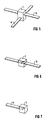
- FIG 2 zeigt ein Anwendungsbeispiel für einen Schnappverbinder, der bodenseitig mit einem zylindrischen, berührungslos arbeitenden Schaltgerät verbunden ist. Neben der Verwendung des Schnappverbinders 1 als Schnittstelle für Elektrogeräte sind die folgenden Anwendungsmöglichkeit denkbar:
- Adapterstück: Rundsteckverbinder-M12-Schnappverbindung (FIG 3)
- Adapterstück: Zwei-Leiter-Klemmstück-Schnappverbindung (FIG 4)
- Kreuzungsstück: Verbindung zweier Leitungen mit Schnappverbinder (FIG 5)
- Verbindungstück: Verlängerung von Leitungen mit Schnappverbinder (FIG 6)
- Abschlußstück: Abdichtung von Leitungsenden mit Schnappverbinder (FIG 7)
- Kabelschelle: Führung und Montage von Leitungen (FIG 8)
- Adapterstück: Zwei-Leiter-Kabelanspritzung-Schnappverbindung (FIG 9)
Claims (12)
- Verbinder mit einer Kontaktierungseinrichtung zur Kontaktierung mit einer verpolungssicher formkodierten elektrischen Leitung (4), im wesentlichen zusammengesetzt aus einem Anschlußblock (2) mit zwei Kontaktspitzen (8) und einer auf den Anschlußblock (2) in Bezug auf die Kontaktspitzen (8) geführt und verdrehsicher aufschnappbaren Klammer (3) mit einem Klammerbett (18), das zur Aufnahme der Leitung (4) dient und in seiner Form der Formkodierung der Leitung (4) angepaßt ist, wobei im aufgeschnappten Zustand die Kontaktspitzen (8) in das Klammerbett (18) ragen und die Leitungsadern der Leitung (4) kontaktieren.
- Verbinder nach Anspruch 1, dadurch gekennzeichnet, daß die beiden Kontaktspitzen (8) derart versetzt angeordnet sind, daß dazwischen Platz zur Montage einer Flachbaugruppe besteht.
- Verbinder nach Anspruch 1 oder 2, dadurch gekennzeichnet, daß die Klammer (3) mit Haltemitteln (15) zur Halterung der Leitung (4) im Klammerbett (18) versehen ist.
- Verbinder nach einem der vorangehenden Ansprüche, dadurch gekennzeichnet, daß die Position der Klammer (3) auf dem Anschlußblock (2) durch Kodiernasen (21) verdrehsicher festgelegt ist.
- Verbinder nach einem der vorangehenden Ansprüche, dadurch gekennzeichnet, daß die richtige Montageposition von Klammer (3) und Anschlußblock (2) zueinander durch in beide Teile eingebrachte Sichtrillen (24) angezeigt ist.
- Verbinder nach einem der vorangehenden Ansprüche, dadurch gekennzeichnet, daß die . Klammer (3) Schnapparme (17) zum Einschnappen in formmäßig angepaßte Führungsnuten (13) des Anschlußblocks (2) aufweist.
- Verbinder nach einem der vorangehenden Ansprüche, dadurch gekennzeichnet, daß der Anschlußblock (2) mit Schnapphaken (15) versehen ist, die im zusammenmontierten Zustand in Schnapparmdurchbrüche (20) der Klammer (3) eingerastet sind.
- Verbinder nach einem der vorangehenden Ansprüche, dadurch gekennzeichnet, daß der Anschlußblock (2) mit einer um die beiden Kontaktspitzen (8) umlaufenden Dichtrippe (9) versehen ist.
- Verbinder nach einem der vorangehenden Ansprüche, dadurch gekennzeichnet, daß eine um die beiden Kontaktspitzen (8) umlaufende Nut (10) im Anschlußblock (2) vorgesehen ist, in die ein O-Ring einlegbar ist.
- Verbinder nach einem der vorangehenden Ansprüche, dadurch gekennzeichnet, daß der Anschlußblock (2) eine Vergußbohrung (12) aufweist.
- Verbinder nach einem der vorangehenden Ansprüche, dadurch gekennzeichnet, daß die Klammer (3) mit Durchbrüchen (22) versehen ist, über die mittels eines geeigneten Werkzeugs die Verrastung der Schnapparme (17) mit Dreh- oder Hebelbewegungen aufhebbar ist.
- Verbinder nach einem der vorangehenden Ansprüche, dadurch gekennzeichnet, daß am Boden (6) des Anschlußblocks (2) außenseitig eine Anspritzung für ein zu verbindendes Elektrogerät angebracht ist.
Priority Applications (1)
| Application Number | Priority Date | Filing Date | Title |
|---|---|---|---|
| EP94914375A EP0694219B1 (de) | 1993-04-14 | 1994-04-14 | Schnappverbinder für elektrische leitungen |
Applications Claiming Priority (6)
| Application Number | Priority Date | Filing Date | Title |
|---|---|---|---|
| EP93106060 | 1993-04-14 | ||
| EP93106060 | 1993-04-14 | ||
| DE4320327A DE4320327C1 (de) | 1993-04-13 | 1993-06-18 | Aktuatoren oder Sensoren zum Anschluß an eine Busleitung |
| DE4320327 | 1993-06-18 | ||
| EP94914375A EP0694219B1 (de) | 1993-04-14 | 1994-04-14 | Schnappverbinder für elektrische leitungen |
| PCT/EP1994/001165 WO1994024728A1 (de) | 1993-04-14 | 1994-04-14 | Schnappverbinder für elektrische leitungen |
Publications (2)
| Publication Number | Publication Date |
|---|---|
| EP0694219A1 EP0694219A1 (de) | 1996-01-31 |
| EP0694219B1 true EP0694219B1 (de) | 1996-10-02 |
Family
ID=27205224
Family Applications (1)
| Application Number | Title | Priority Date | Filing Date |
|---|---|---|---|
| EP94914375A Expired - Lifetime EP0694219B1 (de) | 1993-04-14 | 1994-04-14 | Schnappverbinder für elektrische leitungen |
Country Status (1)
| Country | Link |
|---|---|
| EP (1) | EP0694219B1 (de) |
-
1994
- 1994-04-14 EP EP94914375A patent/EP0694219B1/de not_active Expired - Lifetime
Also Published As
| Publication number | Publication date |
|---|---|
| EP0694219A1 (de) | 1996-01-31 |
Similar Documents
| Publication | Publication Date | Title |
|---|---|---|
| EP3526859B1 (de) | Steckverbinder mit kurzschlussbrücken und verwendungsverfahren | |
| EP1914840B1 (de) | Anschluss-System zur Realisierung von Abzweigungen an durchgehenden Leitern | |
| DE19612575C2 (de) | Vorrichtung zur lösbaren Befestigung von Geräten und zu deren elektrischem Anschließen | |
| EP1096606B1 (de) | Anschlussklemme | |
| EP2567429B1 (de) | Elektrischer baugruppenanschluss eines kraftfahrzeugs | |
| EP2690412B1 (de) | Sensor | |
| DE4320327C1 (de) | Aktuatoren oder Sensoren zum Anschluß an eine Busleitung | |
| DE102016124172A1 (de) | Steckverbinder zur kraftlosen Kontaktierung auf einer Leiterkarte | |
| EP0959533B9 (de) | Gerätesystem | |
| WO1994024728A1 (de) | Schnappverbinder für elektrische leitungen | |
| EP1985162A2 (de) | Halter für eine flexible leiterplatte | |
| EP3728772B1 (de) | Fahrzeugtürgriff | |
| EP3309904B1 (de) | Gehäuse zum anschliessen wenigstens einer kabellitze eines kabels | |
| EP0662741A1 (de) | Niederspannungsschaltgerät | |
| DE9300400U1 (de) | Gehäuse zum Aufnehmen von elektrischen Antrieben | |
| EP1085605B1 (de) | Busleiterabschnitt für ein elektrisches Gerät | |
| DE19647925C1 (de) | Kabelverbinder | |
| EP0694219A1 (de) | Schnappverbinder für elektrische leitungen | |
| EP3688429B1 (de) | Sensor mit anpressfederung | |
| WO1994024727A1 (de) | Aktuatoren oder sensoren zum anschluss an eine busleitung | |
| EP3550667B1 (de) | Anschlussvorrichtung zum anschliessen eines leiters eines kabels an eine tragschiene zu deren elektrischen verbindung miteinander | |
| DE19506713C2 (de) | Mehrpoliger Steckverbinder | |
| EP1542317A1 (de) | Vorrichtung zur Kontaktierung eines elektrischen Leiters | |
| DE3816965C2 (de) | Vorrichtung zur ermittlung von fadenbruch bei einer ringspinn- oder zwirnmaschine | |
| EP1039606B1 (de) | Vorrichtung zum elektrisch leitenden Verbinden von mindestens zwei elektrischen Geräten |
Legal Events
| Date | Code | Title | Description |
|---|---|---|---|
| PUAI | Public reference made under article 153(3) epc to a published international application that has entered the european phase |
Free format text: ORIGINAL CODE: 0009012 |
|
| 17P | Request for examination filed |
Effective date: 19950621 |
|
| AK | Designated contracting states |
Kind code of ref document: A1 Designated state(s): CH DE FR GB LI |
|
| GRAG | Despatch of communication of intention to grant |
Free format text: ORIGINAL CODE: EPIDOS AGRA |
|
| GRAH | Despatch of communication of intention to grant a patent |
Free format text: ORIGINAL CODE: EPIDOS IGRA |
|
| 17Q | First examination report despatched |
Effective date: 19960314 |
|
| GRAH | Despatch of communication of intention to grant a patent |
Free format text: ORIGINAL CODE: EPIDOS IGRA |
|
| GRAA | (expected) grant |
Free format text: ORIGINAL CODE: 0009210 |
|
| AK | Designated contracting states |
Kind code of ref document: B1 Designated state(s): CH DE FR GB LI |
|
| REG | Reference to a national code |
Ref country code: CH Ref legal event code: NV Representative=s name: SIEMENS SCHWEIZ AG |
|
| REF | Corresponds to: |
Ref document number: 59400773 Country of ref document: DE Date of ref document: 19961107 |
|
| GBT | Gb: translation of ep patent filed (gb section 77(6)(a)/1977) |
Effective date: 19961022 |
|
| ET | Fr: translation filed | ||
| PLBE | No opposition filed within time limit |
Free format text: ORIGINAL CODE: 0009261 |
|
| STAA | Information on the status of an ep patent application or granted ep patent |
Free format text: STATUS: NO OPPOSITION FILED WITHIN TIME LIMIT |
|
| 26N | No opposition filed | ||
| REG | Reference to a national code |
Ref country code: GB Ref legal event code: IF02 |
|
| REG | Reference to a national code |
Ref country code: CH Ref legal event code: PCAR Free format text: SIEMENS SCHWEIZ AG;INTELLECTUAL PROPERTY FREILAGERSTRASSE 40;8047 ZUERICH (CH) |
|
| PGFP | Annual fee paid to national office [announced via postgrant information from national office to epo] |
Ref country code: GB Payment date: 20130415 Year of fee payment: 20 Ref country code: DE Payment date: 20130620 Year of fee payment: 20 |
|
| PGFP | Annual fee paid to national office [announced via postgrant information from national office to epo] |
Ref country code: FR Payment date: 20130430 Year of fee payment: 20 |
|
| PGFP | Annual fee paid to national office [announced via postgrant information from national office to epo] |
Ref country code: CH Payment date: 20130708 Year of fee payment: 20 |
|
| REG | Reference to a national code |
Ref country code: DE Ref legal event code: R071 Ref document number: 59400773 Country of ref document: DE |
|
| REG | Reference to a national code |
Ref country code: CH Ref legal event code: PL |
|
| REG | Reference to a national code |
Ref country code: GB Ref legal event code: PE20 Expiry date: 20140413 |
|
| PG25 | Lapsed in a contracting state [announced via postgrant information from national office to epo] |
Ref country code: GB Free format text: LAPSE BECAUSE OF EXPIRATION OF PROTECTION Effective date: 20140413 |
|
| PG25 | Lapsed in a contracting state [announced via postgrant information from national office to epo] |
Ref country code: DE Free format text: LAPSE BECAUSE OF EXPIRATION OF PROTECTION Effective date: 20140415 |