EP0694002B1 - Steuerschaltung für zündpillen umfassende zündkreise - Google Patents
Steuerschaltung für zündpillen umfassende zündkreise Download PDFInfo
- Publication number
- EP0694002B1 EP0694002B1 EP94912452A EP94912452A EP0694002B1 EP 0694002 B1 EP0694002 B1 EP 0694002B1 EP 94912452 A EP94912452 A EP 94912452A EP 94912452 A EP94912452 A EP 94912452A EP 0694002 B1 EP0694002 B1 EP 0694002B1
- Authority
- EP
- European Patent Office
- Prior art keywords
- control circuit
- firing
- transistor
- circuit
- output stage
- Prior art date
- Legal status (The legal status is an assumption and is not a legal conclusion. Google has not performed a legal analysis and makes no representation as to the accuracy of the status listed.)
- Expired - Lifetime
Links
- 238000010304 firing Methods 0.000 title claims abstract 8
- 239000003990 capacitor Substances 0.000 abstract description 4
- 238000000034 method Methods 0.000 description 7
- 238000005259 measurement Methods 0.000 description 4
- 230000004913 activation Effects 0.000 description 2
- 239000003380 propellant Substances 0.000 description 2
- 230000007704 transition Effects 0.000 description 2
- 230000001133 acceleration Effects 0.000 description 1
- 230000006378 damage Effects 0.000 description 1
- 238000010586 diagram Methods 0.000 description 1
- 230000000694 effects Effects 0.000 description 1
- 230000005669 field effect Effects 0.000 description 1
- 230000001771 impaired effect Effects 0.000 description 1
- 239000006187 pill Substances 0.000 description 1
Images
Classifications
-
- B—PERFORMING OPERATIONS; TRANSPORTING
- B60—VEHICLES IN GENERAL
- B60R—VEHICLES, VEHICLE FITTINGS, OR VEHICLE PARTS, NOT OTHERWISE PROVIDED FOR
- B60R21/00—Arrangements or fittings on vehicles for protecting or preventing injuries to occupants or pedestrians in case of accidents or other traffic risks
- B60R21/01—Electrical circuits for triggering passive safety arrangements, e.g. airbags, safety belt tighteners, in case of vehicle accidents or impending vehicle accidents
- B60R21/017—Electrical circuits for triggering passive safety arrangements, e.g. airbags, safety belt tighteners, in case of vehicle accidents or impending vehicle accidents including arrangements for providing electric power to safety arrangements or their actuating means, e.g. to pyrotechnic fuses or electro-mechanic valves
Definitions
- the invention relates to a control circuit for squibs comprising squibs according to the preamble of claim 1.
- Control circuits of the generic type which are known, for example, from EP-A-0 502608, are used in connection with safety devices for vehicle occupants, such as, for example, airbags and / or belt tensioners. They are used to control squibs that ignite a propellant charge that generates the gas quantities required to inflate the airbag.
- An ignition pill is understood to mean an ignition element which can be heated by current flow and which consequently generates the temperature required for igniting an ignition charge.
- the squib thus forms the first link in an electrical-pyrotechnic ignition chain that enables the airbag to be inflated.
- the squib ignites a propellant charge which sets a spool holding the seat belt in rapid revolutions and thus prevents belt loosening.
- Another disadvantage of the known output stages using MOS field-effect transistors is the destruction of the driver circuit in the event of a short circuit between the drain and gate of the associated output stage transistor. This possibility of error is avoided by the circuit arrangement according to the invention.
- the proposed control circuit enables both the squib resistance and the squib circuit capacitance to be monitored. Especially when measuring the resistance value, it is necessary that the output stages can be switched through and blocked again as quickly as possible in order to prevent the measurement from being falsified when passing through the transition region. This is also achieved with the proposed control circuit.
- the switching-off process of the transistors T2, T3 of the output stage is greatly accelerated by the proposed control circuit.
- the RC combinations R1, C1 and R2, C2 connected between the gate connections of the transistors T2, T3 and the base connection of the transistor T1 ensure that the switch-off process takes only about 100 nanoseconds.
- the shutdown process would not be complete without these RC combinations after approx. 2 microseconds.
- the measurement accuracy of the ignition circuit monitors especially in the case of large temperature fluctuations, such as occur in vehicles, is improved many times over.
- each output stage T2, T3 remains independent of the function of the other output stage. This would not be the case with a solution with a common push-pull driver stage for both output stages.
- a short circuit of the transistors T2, T3 can also be recognized and displayed on the basis of a resistance measurement.
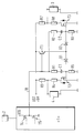
- reference numeral 1 denotes a controller whose output port is represented by a schematically indicated push-pull output stage with transistors T4 and T5.
- a sensor 2 is in operative connection with the controller 1, which detects accelerations acting on the vehicle, which are evaluated by the controller 1.
- a control line 10 is connected to the push-pull output stage T4, T5 (output port of the controller 1), which is connected to the base connection as a driver stage provided transistor T1 leads.
- the collector terminal of the transistor T1 is connected to the positive pole of a stabilized voltage source, +5 V in the present case.
- the emitter connection of the transistor T1 is connected to the anode connection of the diodes D1 and D2, which are in particular Schottky diodes.
- the cathode connection of the diode D1 is connected to the gate connection of a first output stage transistor T2.
- a resistor R5 is connected between the gate terminal of transistor T2 and ground.
- the base connection of the transistor T1 of the driver stage and the gate connection of the transistor T2 of the first output stage are connected to one another via the series connection of a resistor R1 and a capacitor C1.
- the source terminal of transistor T2 is connected to ground.
- the drain connection of the transistor T2 is connected to the positive pole of the operating voltage UST via the series connection of the resistors R3, R4.
- a first ignition circuit 4 lies between the connection point of the resistors R3, R4 and the ground connection.
- the cathode connection of the second diode D2 is connected to the gate connection of the transistor T3 of the second output stage.
- the resistor R6 is connected between the gate connection and the ground connection.
- the gate terminal of transistor T3 and the base terminal of transistor T1 are connected to one another via the series circuit of a resistor R2 and a capacitor C2.
- the source terminal of transistor T3 is connected to ground, while its drain terminal is connected to the positive pole of the stabilized voltage UST via the series circuit of resistors R8, R7.
- a second ignition circuit 3 is connected between the connection point of the resistors R7 and R8 and the ground connection.
- the control line 10 of the controller 1 is set to high potential.
- transistor T1 of the driver stage is switched on, so that a large current can briefly flow through it and diodes D1, D2 into the gate electrodes of transistors T2, T3.
- the gate-source capacities are charged very quickly. Consequently the transistors T2, T3 of the output stages are completely turned on within a few nanoseconds and are therefore in the switching mode.
- This switch-on process is also supported by the series circuits R2, C1 or R2, C2, since in addition to the current of the transistor T1 of the driver stage, the switch-on current peak on the control line 10 is also conducted into the gate connections of the transistors T2, T3.
- the control line 10 of the controller 1 is put back to low potential. since the transistor T1 of the driver stage is operated in a collector circuit, this immediately blocks the drive voltage for the transistors T2, T3 of the output stages.
- the gate-source capacitances of the transistors T2, T3 can discharge into the push-pull output stage T4, T5 of the controller 1 via the RC combinations R1, C1 or R2, C2. This discharge process takes place very quickly since the control line 10 of the controller 1 is internally connected to ground with a low resistance.
- Such controller connections usually have a relatively high sinking current capacity and a comparatively low resistance value R DSON of 100 ohms.
- the transistors T2, T3 of the output stages are blocked by this measure within a period of 100 nanoseconds, so that the transition region is passed through very quickly.
- the independence of the control of the two output stage transistors T2, T3 is not impaired. If, for example, transistor T3 of the second output stage has a short circuit between its drain and gate connections, the activation of transistor T2 of the first output stage is slowed down; however, this has no effect on the ignitability of an airbag that can be activated by the ignition circuit 1. This also applies, of course, to a short circuit in transistor T2 of the first output stage. Resistance measurement is influenced by the slowing down of the switching process in the output stage transistor T2. This provides an additional way of identifying faults within the output stages.
Landscapes
- Engineering & Computer Science (AREA)
- Mechanical Engineering (AREA)
- Air Bags (AREA)
- Automotive Seat Belt Assembly (AREA)
- Electronic Switches (AREA)
Abstract
Description
- Die Erfindung betrifft eine Steuerschaltung für Zündpillen umfassende Zündkreise nach dem Oberbegriff des Anspruchs 1.
- Steuerschaltungen der gattungsgemäßen Art die beispielsweise aus EP-A-0 502608 bekannt sind, werden im Zusammenhang mit Sicherheitseinrichtungen für Fahrzeuginsassen, wie beispielsweise Airbag und/oder Gurtstraffer, eingesetzt. Sie dienen der Ansteuerung von Zündpillen, die eine Treibladung zünden, welche die zum Aufblasen des Airbag erforderlichen Gasmengen erzeugt. Unter einer Zündpille versteht man ein Zündelement, das durch Stromfluß aufheizbar ist und das demzufolge die für das Anzünden einer Zündladung notwendige Temperatur erzeugt. Die Zündpille bildet damit das erste Glied einer elektrisch-pyrotechnischen Zündkette, die das Aufblasen des Airbag ermöglicht. Bei einem pyrotechnischen Gurtstraffer zündet die Zündpille eine Treibladung, die eine den Sicherheitsgurt aufnehmende Spule in schnelle Umdrehungen versetzt und damit Gurtlose verhindert.
- Gegenüber herkömmlichen Endstufen mit einer in Gegentaktschaltung ausgeführten Treiberstufe zeichnet sich die vorgeschlagene Steuerschaltung durch einen vergleichsweise einfachen Schaltungsaufbau aus, da nur noch eine einzige Treiberstufe vorgesehen ist. Dennoch kann jede der von der Treiberstufe angesteuerten Endstufen unabhängig voneinander angesteuert werden.
- Ein weiterer Nachteil der bekannten, MOS-Feldeffekttransistoren verwendenden Endstufen ist die Zerstörung der Treiberschaltung bei einem Kurzschluß zwischen Drain und Gate des zugeordneten Endstufentransistors. Diese Fehlermöglichkeit wird durch die erfindungsgemäße Schaltungsanordnung vermieden. Insbesondere bei Zündkreisen, in denen ein Zündkreiskondensator in Reihe zu der Zündpille geschaltet ist, ermöglicht die vorgeschlagene Steuerschaltung sowohl die Überwachung des Zündpillenwiderstandes als auch der Zündkreiskapazität. Speziell bei der Messung des Widerstandswertes ist es notwendig, daß die Endstufen möglichst schnell durchgeschaltet und wieder gesperrt werden können, um eine Verfälschung der Messung beim Durchlaufen des Übergangsbereiches zu verhindern. Auch dies wird mit der vorgeschlagenen Steuerschaltung erreicht.
- Der Abschaltvorgang der Transistoren T2, T3 der Endstufe wird durch die vorgeschlagene Steuerschaltung stark beschleunigt. So sorgen die zwischen den Gate-Anschlüssen der Transistoren T2, T3 und dem Basisanschluß des Transistors T1 geschalteten RC-Kombinationen R1, C1 bzw. R2, C2 dafür, daß der Abschaltvorgang nur etwa 100 Nanosekunden in Anspruch nimmt. Im Vergleich dazu wäre der Abschaltvorgang ohne diese RC-Kombinationen erst nach ca. 2 Mikrosekunden beendet. Dadurch wird die Meßgenauigkeit der Zündkreisüberwachungen, vor allem bei großen Temperaturschwankungen, wie sie bei Fahrzeugen auftreten, um ein Vielfaches verbessert.
- Der Einschaltvorgang wird ebenfalls beschleunigt, was zu einer weiteren Genauigkeitssteigerung führt. Mit der vorgeschlagenen Steuerschaltung können Ströme von einigen Ampere innerhalb von rund 200 Nanosekunden ein- und ausgeschaltet werden.
- Diese Vorteile werden mit einem vergleichsweise geringen Bauteileaufwand erzielt, da anstelle eingesparten Treiberstufe lediglich wenige passive Bauelemente, nämlich R1, C1 und R2, C2 in der Schaltungsanordnung vorgesehen werden müssen.
- Weiterhin bleibt die Ansteuerung jeder Endstufe T2, T3 unabhängig von der Funktion der anderen Endstufe. Dies wäre bei einer Lösung mit einer gemeinsamen Gegentakt-Treiberstufe für beide Endstufen nicht der Fall.
- Schließlich kann auch ein Kurzschluß der Transistoren T2, T3 aufgrund einer Widerstandsmessung erkannt und zur Anzeige gebracht werden.
- Ein Ausführungsbeispiel der Erfindung wird nachfolgend anhand der Zeichnung näher erläutert, die einen schematisierten Stromlaufplan der Steuerschaltung darstellt.
- In der Figur ist mit Bezugsziffer 1 ein Controller bezeichnet, dessen Ausgangsport durch eine schematisch angedeutete Gegentaktendstufe mit den Transistoren T4 und T5 dargestellt ist. Mit dem Controller 1 in Wirkverbindung steht ein Sensor 2, der auf das Fahrzeug einwirkende Beschleunigungen erfaßt, die von dem Controller 1 ausgewertet werden. Mit der Gegentaktendstufe T4, T5 (Ausgangsport des Controllers 1) ist eine Ansteuerleitung 10 verbunden, die an den Basisanschluß eines als Treiberstufe vorgesehenen Transistors T1 führt. Der Kollektoranschluß des Transistors T1 ist mit dem Pluspol einer stabilisierten Spannungsquelle, im vorliegenden Fall +5 V, verbunden. Der Emitteranschluß des Transistors T1 ist mit dem Anodenanschluß der Dioden D1 und D2 verbunden, bei denen es sich insbesondere um Schottkydioden handelt. Der Kathodenanschluß der Diode D1 ist mit dem Gateanschluß eines ersten Endstufentransistors T2 verbunden. Zwischen den Gateanschluß des Transistors T2 und Masse ist ein Widerstand R5 geschaltet. Der Basisanschluß des Transistors T1 der Treiberstufe und der Gateanschluß des Transistors T2 der ersten Endstufe sind über die Serienschaltung eines Widerstands R1 und eines Kondensators C1 miteinander verbunden. Der Sourceanschluß des Transistors T2 ist mit Masse verbunden. Der Drainanschluß des Transistors T2 ist über die Serienschaltung der Widerstände R3, R4 mit dem positiven Pol der Betriebsspannung UST verbunden. Ein erster Zündkreis 4 liegt zwischen dem Verbindungspunkt der Widerstände R3, R4 und dem Masseanschluß. Der Kathodenanschluß der zweiten Diode D2 ist mit dem Gateanschluß des Transistors T3 der zweiten Endstufe verbunden. Zwischen dem Gateanschluß und dem Masseanschluß ist der Widerstand R6 geschaltet. Der Gateanschluß des Transistors T3 und der Basisanschluß des Transistors T1 sind über die Serienschaltung eines Widerstandes R2 und eines Kondensators C2 miteinander verbunden. Der Sourceanschluß des Transistors T3 ist mit Masse verbunden, während sein Drainanschluß über die Serienschaltung der Widerstände R8, R7 mit dem positiven Pol der stabilisierten Spannung UST verbunden ist. Zwischen dem Verbindungspunkt der Widerstände R7, und R8 und dem Masseanschluß ist ein zweiter Zündkreis 3 geschaltet.
- Zum Einschalten der Transistoren T2, T3 der Endstufen wird die Ansteuerleitung 10 des Controllers 1 auf High-Potential gelegt. Dadurch wird Transistor T1 der Treiberstufe durchgeschaltet, so daß über ihn und die Dioden D1, D2 kurzzeitig ein großer Strom in die Gate-Elektroden der Transistoren T2, T3 fließen kann. Dadurch werden die Gate-Source-Kapazitäten sehr schnell aufgeladen. Infolgedessen werden die Transistoren T2, T3 der Endstufen innerhalb weniger Nanosekunden vollkommen durchgesteuert und befinden sich demzufolge im Schaltbetrieb. Durch die Serienschaltungen R2, C1 bzw. R2, C2 wird dieser Einschaltvorgang noch unterstützt, da zusätzlich zum Strom des Transistors T1 der Treiberstufe auch noch die Einschaltstromspitze auf der Steuerleitung 10 in die Gate-Anschlüsse der Transistoren T2, T3 geleitet wird. Um die Endstufen abzuschalten, wird die Steuerleitung 10 des Controllers 1 wieder auf Low-Potential gelegt. da der Transistor T1 der Treiberstufe in Kollektorschaltung betrieben wird, sperrt dieser sofort die Ansteuerspannung für die Transistoren T2, T3 der Endstufen. Die Gate-Source-Kapazitäten der Transistoren T2, T3 können sich über die RC-Kombinationen R1, C1 bzw. R2, C2 in die Gegentaktendstufe T4, T5 des Controllers 1 entladen. Dieser Entladevorgang geht sehr schnell vor sich, da die Steuerleitung 10 des Controllers 1 intern niederohmig nach Masse geschaltet ist. Üblicherweise haben derartige Controller-Anschlüsse eine relativ hohe Sinkstromkapazität und einen vergleichsweise geringen Widerstandswert RDSON von 100 Ohm. Die Transistoren T2, T3 der Endstufen sperren durch diese Maßnahme innerhalb eines Zeitraums von 100 Nanosekunden, so daß der Übergangsbereich sehr schnell durchschritten wird. Die Unabhängigkeit der Ansteuerung der beiden Endstufentransistoren T2, T3 wird nicht beeinträchtigt. Hat zum Beispiel Transistor T3 der zweiten Endstufe einen Kurzschluß zwischen seinen Drain- und Gateanschlüssen, so wird zwar die Ansteuerung des Transistors T2 der ersten Endstufe verlangsamt; dies hat jedoch keine Auswirkung auf die Zündfähigkeit eines durch den Zündkreis 1 aktivierbaren Airbags. Sinngemäß gilt dies natürlich auch bei einem Kurzschluß in dem Transistor T2 der ersten Endstufe. Durch die Verlangsamung des Schaltvorgangs bei dem Endstufentransistor T2 wird eine Widerstandsmessung jedoch beeinflußt. Dadurch ergibt sich eine zusätzliche Möglichkeit, Fehler innerhalb der Endstufen zu erkennen.
Claims (5)
- Steuerschaltung für Zündpillen umfassende Zündkreise, dadurch gekennzeichnet, daß für jeden Zündkreis (3, 4) eine unabhängig voneineinander ansteuerbare Endstufe mit je einem Transistor (T2, T3) vorgesehen ist, die von einer gemeinsamen Treiberstufe (T1) ansteuerbar sind.
- Steuerschaltung nach Anspruch 1, dadurch gekennzeichnet, daß jeder Endstufe (T2, T3) eine RC-Kombination (R1, C1, R2, C2) zugeordnet ist.
- Steuerschaltung nach einem der Ansprüche 1, 2, dadurch gekennzeichnet, daß jeder Endstufe (T2, T3) eine Diode (D1, D2) zugeordnet ist.
- Steuerschaltung nach einem der Ansprüche 1 bis 3, dadurch gekennzeichnet, daß als Dioden (D1, D2) Schottky-Dioden vorgesehen sind.
- Steuerschaltung nach einem der Ansprüche 1 bis 4, dadurch gekennzeichnet, daß die Widerstandswerte (R1, R2) und die Kapazitätswerte (C1, C2) der RC-Kombinationen (R1, C1, R2, C2) zwischen 50 Ohm und 1 kOhm, insbesondere 100 Ohm und zwischen 1 Nanofarad und 10 Nanofarad, insbesondere bei 5 Nanofarad liegen.
Applications Claiming Priority (3)
| Application Number | Priority Date | Filing Date | Title |
|---|---|---|---|
| DE4313124 | 1993-04-22 | ||
| DE4313124A DE4313124A1 (de) | 1993-04-22 | 1993-04-22 | Steuerschaltung für Zündpillen umfassende Zündkreise |
| PCT/DE1994/000410 WO1994023971A1 (de) | 1993-04-22 | 1994-04-13 | Steuerschaltung für zündpillen umfassende zündkreise |
Publications (2)
| Publication Number | Publication Date |
|---|---|
| EP0694002A1 EP0694002A1 (de) | 1996-01-31 |
| EP0694002B1 true EP0694002B1 (de) | 1996-12-27 |
Family
ID=6486077
Family Applications (1)
| Application Number | Title | Priority Date | Filing Date |
|---|---|---|---|
| EP94912452A Expired - Lifetime EP0694002B1 (de) | 1993-04-22 | 1994-04-13 | Steuerschaltung für zündpillen umfassende zündkreise |
Country Status (4)
| Country | Link |
|---|---|
| EP (1) | EP0694002B1 (de) |
| JP (1) | JPH08509183A (de) |
| DE (2) | DE4313124A1 (de) |
| WO (1) | WO1994023971A1 (de) |
Families Citing this family (5)
| Publication number | Priority date | Publication date | Assignee | Title |
|---|---|---|---|---|
| DE19655380C5 (de) * | 1995-10-26 | 2014-04-10 | Robert Bosch Gmbh | Airbagsystem |
| US5725242A (en) * | 1996-02-09 | 1998-03-10 | Siemens Automotive Corporation | Airbag squib with silicon circuit and energy storage |
| US5734317A (en) * | 1996-07-01 | 1998-03-31 | Motorola, Inc. | Current limit controller for an air bag deployment system |
| DE10027182C1 (de) * | 2000-05-31 | 2001-10-31 | Siemens Ag | Vorrichtung zur Energieversorgung eines Zündmittels eines Insassenrückhaltemittels |
| DE102005045233A1 (de) * | 2005-09-22 | 2007-03-29 | Robert Bosch Gmbh | Steuergerät für den Personenschutz |
Family Cites Families (2)
| Publication number | Priority date | Publication date | Assignee | Title |
|---|---|---|---|---|
| DE9012215U1 (de) * | 1990-08-24 | 1990-10-25 | Siemens AG, 80333 München | Anordnung von einem Zündsteuergerät und von Crashsensoren in einem Fahrzeug |
| US5194755A (en) * | 1991-03-04 | 1993-03-16 | Ford Motor Company | Airbag triggering system |
-
1993
- 1993-04-22 DE DE4313124A patent/DE4313124A1/de not_active Withdrawn
-
1994
- 1994-04-13 DE DE59401408T patent/DE59401408D1/de not_active Expired - Fee Related
- 1994-04-13 EP EP94912452A patent/EP0694002B1/de not_active Expired - Lifetime
- 1994-04-13 JP JP6522620A patent/JPH08509183A/ja active Pending
- 1994-04-13 WO PCT/DE1994/000410 patent/WO1994023971A1/de not_active Ceased
Also Published As
| Publication number | Publication date |
|---|---|
| DE4313124A1 (de) | 1994-10-27 |
| EP0694002A1 (de) | 1996-01-31 |
| WO1994023971A1 (de) | 1994-10-27 |
| DE59401408D1 (de) | 1997-02-06 |
| JPH08509183A (ja) | 1996-10-01 |
Similar Documents
| Publication | Publication Date | Title |
|---|---|---|
| EP0781216B1 (de) | Elektronische sicherheitseinrichtung für fahrzeuginsassen | |
| EP0400002B1 (de) | Verfahren zum betrieb einer sicherheitseinrichtung für fahrzeuginsassen | |
| DE4413194C2 (de) | Fehlerdiagnosegerät für eine Steuerschaltung einer Fahrzeugpassagier-Schutzvorrichtung | |
| EP0284728B1 (de) | Schaltungsanordnung zum Auslösen eines Schutzsystems | |
| DE3876454T4 (de) | Airbag-system zum schützen von kraftfahrzeuginsassen. | |
| DE2454424C3 (de) | Schaltung für einen elektronischen Sensor zur Auslösung einer Sicherheitsvorrichtung | |
| EP0380485B1 (de) | Verfahren zum betrieb einer sicherheitseinrichtung für fahrzeuginsassen | |
| DE19614365C2 (de) | Diagnoseschaltung zur Prüfung der Kapazität eines Kondensators | |
| EP0011680A1 (de) | Prüfschaltung für die Auslösevorrichtung einer den Schutz der Insassen eines Fahrzeugs während eines Unfalles dienenden Sicherheitseinrichtung | |
| DE10255115B3 (de) | Ansteuerschaltung für eine Zündpille eines Fahrzeugrückhaltesystems | |
| DE4210861B4 (de) | Elektrischer Steuerschaltkreis für ein Insassen-Schutzsystem in Kraftfahrzeugen | |
| WO1994023971A1 (de) | Steuerschaltung für zündpillen umfassende zündkreise | |
| WO1997008022A1 (de) | Feedbackgesteuerte zündpillenaktivierung für einen gassack eines kraftfahrzeuges | |
| DE4447174A1 (de) | Elektronische Sicherheitseinrichtung für Fahrzeuginsassen | |
| WO1988001241A1 (fr) | Element de commande et de controle de circuits d'allumage | |
| DE19617250C1 (de) | Schaltungsanordnung zum Verhindern von Fehlauslösungen von Insassenschutzsystemen | |
| DE3920693A1 (de) | Ausloesekreis-ueberwachungsschaltung, insbesondere in fahrzeuginsassen-sicherheitssystemen | |
| EP1028874B1 (de) | Verfahren und zündschaltung zur auslösung eines insassenschutzsystems | |
| WO1998012082A1 (de) | Schaltungsanordnung zur strombegrenzung in einem schutzsystem, insbesondere airbag-steuersystem | |
| WO1999028168A1 (de) | Kraftfahrzeug-insassenschutzsystem mit mehreren zündpillen, und verfahren zum ansteuern eines zündkreises eines solchen insassenschutzsystems | |
| WO1989009147A1 (fr) | Dispositif electronique | |
| EP1133419A1 (de) | Steuervorrichtung für ein insassenschutzmittel und verfahren zum steuern eines insassenschutzmittels | |
| DE19641793B4 (de) | Rückhaltesystem für Kraftfahrzeuge | |
| DE69804931T2 (de) | Zündschaltung für Airbag | |
| EP2703231B1 (de) | Sensorik für ein Personenschutzsystem in einem Fahrzeug und Personenschutz-system für ein Fahrzeug |
Legal Events
| Date | Code | Title | Description |
|---|---|---|---|
| PUAI | Public reference made under article 153(3) epc to a published international application that has entered the european phase |
Free format text: ORIGINAL CODE: 0009012 |
|
| 17P | Request for examination filed |
Effective date: 19951122 |
|
| AK | Designated contracting states |
Kind code of ref document: A1 Designated state(s): DE FR GB |
|
| GRAG | Despatch of communication of intention to grant |
Free format text: ORIGINAL CODE: EPIDOS AGRA |
|
| GRAH | Despatch of communication of intention to grant a patent |
Free format text: ORIGINAL CODE: EPIDOS IGRA |
|
| 17Q | First examination report despatched |
Effective date: 19960614 |
|
| GRAH | Despatch of communication of intention to grant a patent |
Free format text: ORIGINAL CODE: EPIDOS IGRA |
|
| GRAA | (expected) grant |
Free format text: ORIGINAL CODE: 0009210 |
|
| AK | Designated contracting states |
Kind code of ref document: B1 Designated state(s): DE FR GB |
|
| REF | Corresponds to: |
Ref document number: 59401408 Country of ref document: DE Date of ref document: 19970206 |
|
| ET | Fr: translation filed | ||
| GBT | Gb: translation of ep patent filed (gb section 77(6)(a)/1977) |
Effective date: 19970227 |
|
| PLBE | No opposition filed within time limit |
Free format text: ORIGINAL CODE: 0009261 |
|
| STAA | Information on the status of an ep patent application or granted ep patent |
Free format text: STATUS: NO OPPOSITION FILED WITHIN TIME LIMIT |
|
| 26N | No opposition filed | ||
| PGFP | Annual fee paid to national office [announced via postgrant information from national office to epo] |
Ref country code: GB Payment date: 19990326 Year of fee payment: 6 |
|
| PGFP | Annual fee paid to national office [announced via postgrant information from national office to epo] |
Ref country code: FR Payment date: 19990427 Year of fee payment: 6 |
|
| PGFP | Annual fee paid to national office [announced via postgrant information from national office to epo] |
Ref country code: DE Payment date: 19990712 Year of fee payment: 6 |
|
| PG25 | Lapsed in a contracting state [announced via postgrant information from national office to epo] |
Ref country code: GB Free format text: LAPSE BECAUSE OF NON-PAYMENT OF DUE FEES Effective date: 20000413 |
|
| GBPC | Gb: european patent ceased through non-payment of renewal fee |
Effective date: 20000413 |
|
| PG25 | Lapsed in a contracting state [announced via postgrant information from national office to epo] |
Ref country code: FR Free format text: LAPSE BECAUSE OF NON-PAYMENT OF DUE FEES Effective date: 20001229 |
|
| PG25 | Lapsed in a contracting state [announced via postgrant information from national office to epo] |
Ref country code: DE Free format text: LAPSE BECAUSE OF NON-PAYMENT OF DUE FEES Effective date: 20010201 |
|
| REG | Reference to a national code |
Ref country code: FR Ref legal event code: ST |