EP0692892A2 - Verfahren und Ausrüstung zur Echtheitverwaltung von Kommunikationsmitteln in einem virtuellen Privatnetz in ATM-Technik - Google Patents
Verfahren und Ausrüstung zur Echtheitverwaltung von Kommunikationsmitteln in einem virtuellen Privatnetz in ATM-Technik Download PDFInfo
- Publication number
- EP0692892A2 EP0692892A2 EP95201884A EP95201884A EP0692892A2 EP 0692892 A2 EP0692892 A2 EP 0692892A2 EP 95201884 A EP95201884 A EP 95201884A EP 95201884 A EP95201884 A EP 95201884A EP 0692892 A2 EP0692892 A2 EP 0692892A2
- Authority
- EP
- European Patent Office
- Prior art keywords
- atm
- cell
- transmission bandwidth
- node
- reservation
- Prior art date
- Legal status (The legal status is an assumption and is not a legal conclusion. Google has not performed a legal analysis and makes no representation as to the accuracy of the status listed.)
- Granted
Links
Images


Classifications
-
- H—ELECTRICITY
- H04—ELECTRIC COMMUNICATION TECHNIQUE
- H04L—TRANSMISSION OF DIGITAL INFORMATION, e.g. TELEGRAPHIC COMMUNICATION
- H04L12/00—Data switching networks
- H04L12/54—Store-and-forward switching systems
- H04L12/56—Packet switching systems
- H04L12/5601—Transfer mode dependent, e.g. ATM
- H04L12/5602—Bandwidth control in ATM Networks, e.g. leaky bucket
-
- H—ELECTRICITY
- H04—ELECTRIC COMMUNICATION TECHNIQUE
- H04Q—SELECTING
- H04Q11/00—Selecting arrangements for multiplex systems
- H04Q11/04—Selecting arrangements for multiplex systems for time-division multiplexing
- H04Q11/0428—Integrated services digital network, i.e. systems for transmission of different types of digitised signals, e.g. speech, data, telecentral, television signals
- H04Q11/0478—Provisions for broadband connections
-
- H—ELECTRICITY
- H04—ELECTRIC COMMUNICATION TECHNIQUE
- H04L—TRANSMISSION OF DIGITAL INFORMATION, e.g. TELEGRAPHIC COMMUNICATION
- H04L12/00—Data switching networks
- H04L12/54—Store-and-forward switching systems
- H04L12/56—Packet switching systems
- H04L12/5601—Transfer mode dependent, e.g. ATM
- H04L2012/5629—Admission control
- H04L2012/563—Signalling, e.g. protocols, reference model
-
- H—ELECTRICITY
- H04—ELECTRIC COMMUNICATION TECHNIQUE
- H04L—TRANSMISSION OF DIGITAL INFORMATION, e.g. TELEGRAPHIC COMMUNICATION
- H04L12/00—Data switching networks
- H04L12/54—Store-and-forward switching systems
- H04L12/56—Packet switching systems
- H04L12/5601—Transfer mode dependent, e.g. ATM
- H04L2012/5629—Admission control
- H04L2012/5631—Resource management and allocation
- H04L2012/5632—Bandwidth allocation
- H04L2012/5634—In-call negotiation
Definitions
- the present invention relates in general to communication systems employing the digital technique called fast cell switching or Asynchronous Transfer Mode (ATM), for the transport of voice and video signals and data.
- ATM Asynchronous Transfer Mode
- the invention relates a method and an equipment for the real time management of resources in a virtual private network according to the ATM technique.
- the ATM technique has an ever higher importance in the control of the integrated switching of digital signal flows belonging to services for the transmission of voice and video signals and data, with different bandwidth requirements and traffic characteristics differentiate among the different services.
- the ATM technique foresees in particular that information relevant to the different services are organized in information units having 53 bytes fixed length, called cells. These cells contain, besides actual user's data, a header carrying the information necessary to the geographical routing of the cell itself through the network.
- AVPN ATM Virtual Private Network
- AVPN networks involve advantages for the user in terms of cost saving, connection capacity and flexibility.
- the resources offered by networks in ATM technique can even not be firmly associated to a single call for the whole duration of the same, but can be assigned to the call in the quantity and for the time strictly required to transmit user's information.
- the dimensioning of the resources used by an AVPN is made controlling the allocation in real time of resources, on the basis of the knowledge of traffic interests of users abutted to the AVPN itself.
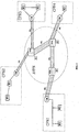
- Fig. 1 shows the basic diagram of a virtual private network AVPN (ATM Virtual Private Network) connecting a plurality of local networks CPN1, CPN2,...CPNn (Customer Premises Network) located in places even very far among them, from the geographical point of view.
- AVPN ATM Virtual Private Network
- CPN1, CPN2,...CPNn Customer Premises Network
- Each single local network is abutted, through a relevant interface device CM (CPN Manager), to access nodes of an ATM public network.
- Each local network CPN includes one or more user terminals WS.
- the AVPN network is configured as a completely meshed network of VCCs (Virtual Channel Connections) consisting in their turn of virtual links VCLs (Virtual Channel Links).
- VCCs Virtual Channel Connections
- VCLs Virtual Channel Links
- VCL Virtual Path Link
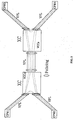
- Fig. 2 shows more in detail the grouping of the different links of VCCs inside VPLs.
- Cross connect points of the ATM network marked XC in Fig. 2, are fit, among other things, with capability of virtual channels (VC) switching.
- VC virtual channels
- a transmission bandwidth is associated to each VPL, which is reserved by the operating company of the ATM public network, to the AVPN network.
- This transmission bandwidth is agreed between the user and the public network operator at the AVPN setup time, on the basis of a trade off between the user's traffic needs, and of the service cost.
- Each VPL consists of a pool of VCC. Each one of them has to observe at input the bandwidth parameter negotiated between the user and the network on AVPN set-up. The bandwidth of each VCC is dynamically negotiated.
- the total value of the bandwidth actually employed by the user is obtained as a simple summation of the bandwidths of each one of the VCCs abutted in each VPL coming out from a node.
- each one of the nodes involved in the AVPN topology it is however possible to newly check in real time the bandwidth actually employed by the user, due to the "scattering" of VCCs and recomposition of VPL in new VPL.
- this bandwidth limit shall be considered hereafter static, but this does not exclude that this bandwidth can be changed against variation of the need for transmission bandwidth by the user of the AVPN network, as for a reconfiguration of the AVPN itself.
- one single VCC occupies all the transmission bandwidth allocated to one of the VPLs concurring to interconnect two CPNs.
- connections of other users of the public network could be compromised or even, the whole ATM access node could be blocked.
- PF control functions to dynamically enable the use of the transmission bandwidth, are implemented.
- PF functions are performed at inputs and outputs of each cross connect XC.
- control functions PF are performed, always according to this proposal, both on VPL at input, and on VPL at output, just because several VCC at input in an XC node could be all switched toward the same VPL at output.
- a first problem is represented by the fact that, in this way, local CPNs must always dialogue between them and must always know the load condition of each single path of the network.
- a second and more serious problem is that with such a solution it is not possible to implement in a simple way, traffic control functions capable to protect a node against congestion, occurring for instance for the concentration of several VCCs towards a unique VPL.
- Particular object of the present invention is to supply a method not requiring to the ATM node to implement heavy functions for the detection and transmission of information relevant to the occupation condition of each virtual path VPL of such virtual private network.
- Additional objects of this invention is to supply a simple, effective and low cost equipment for dynamic management of shared resource.
- a virtual private network ATM connecting a plurality of user local networks located in places even very far among them from the geographical point of view and each one abutted to an access node of an ATM public network whose information relevant to the different services is organized as information units having fixed length called ATM cells
- said public network ATM supporting a Fast Resource Management protocol called FRM and said virtual private network being configured as a completely meshed network of virtual channel connections consisting in their turn of virtual links, said virtual channel links being grouped, among different pairs of nodes and egress nodes in virtual path links through transit nodes and a transmission bandwidth agreed between the user of the virtual private network and the managing company of the public network ATM being reserved to said virtual path links, characterized by the fact to include for each user of said virtual private network abutted to an input access node of said public network ATM willing to transmit data with a given transmission bandwidth toward another user of said virtual private network abutted to another destination access node of said ATM network, the following
- the invention consists also of an equipment for the management in real time of the resources in a virtual private network in ATM technique connecting a plurality of user local networks located in places even distant among them from the geographical point of view and each one abutted to an access node of a public network ATM in which information relevant to the different services is organized as information units having fixed length called ATM cells, said public network ATM supporting a protocol of Fast Resource Management called FRM, said AVPN network being configured as a meshed network of virtual channel connections consisting in their turn of virtual channel links, said virtual channel links being grouped, among different pairs of access nodes and egress nodes in virtual path links through transit nodes and being reserved to said virtual path links a transmission bandwidth agreed between the user of the virtual private network and the managing company of the public network ATM, characterized by the fact to include, for each one of said nodes, a relevant server device at least connected to an output link of the relevant node, on which all ATM cells of the FRM type transit and cross the subject node, and to an input link of the relevant node, on which
- FRM cells Full Resource Management
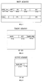
- FIG. 3 The structure of an ATM cell of the FRM type, particular case of the more general structure of Resource Management (RM) cell, is shown in Fig. 3.
- RM Resource Management
- the header HEADER of an ATM cell contains a virtual path identifier (Virtual Path Identifier), a virtual channel identifier VCI (Virtual Channel identifier), a payload type identifier PTI (Payload Type Identifier), a priority level identifier CLP (Cell Loss Priority) and a header error control field HEC (Header Error Control).
- RM cells can be distinguished from other ATM cells for the presence of value 110 included in the header PTI field. Also, the indication relevant to the specific FRM protocol is contained in the first byte PI (Protocol Identifier) of the payload.
- PI Protocol Identifier
- the FRM protocol having higher level compared to the ATM protocol, is transported in the subsequent field of the cell payload.
- the payload of the FRM cell contains a field indicating the type of FRM cell.
- Subsequent field of the payload contain information relevant to the protocol.
- some field of the payload of FRM cells are used to contain the values of bandwidth parameters of the VCC one wants to modify.
- FRM cell types are the following:
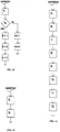
- Fig. 4 shows the elements of the AVPN involved in information exchanges relevant to bandwidth request phases preceding the transmission of data and the bandwidth release at the end of data transmission.
- the access node of the AVPN network to which the user network CPN willing to transmit its data is connected, has been indicated with AN (Access Node).
- the access node is connected to the Egress Node through a plurality of transit nodes TN1, TN2, TNn (Transit Node).
- the user local network CPN Before starting the transmission of data, the user local network CPN sends toward the access node AN a Reservation Request type cell. Another field of this FRM cell, still transported in the payload, contains inside a parameter BAND_REQ indicating the value of the requested transmission bandwidth.
- the access node AN transmits toward the user network CPN a Reservation Received cell indicating the occurred reception of the previous Reservation Request type cell.
- the access node AN attempts to reserve the bandwidth value indicated by the parameter BAN_REQ, for the VCC indicated by the request by the user network CPN.
- the access node AN transmits toward the user network CPM a Reservation Denied type cell.
- the access node AN before transmitting the Reservation Denied type cell can proceed to a preset number of reservation reattempts, spaced according to a time-out T1.
- the access node AN sends a Reservation Request type cell whose payload contains, once again, the BAN_REQ parameter indicating the value of the required transmission bandwidth toward the first transit node TN1.
- the access node AN updates the bandwidth value temporarily available on the CPL at output, subtracting the BAND_REQ value.
- the transit node TN1 attempts to reserve the bandwidth value indicated by the parameter BAND_REQ on the subsequent VPL.
- the transit node TN1 transmits toward the access node AN a Reservation Denied type cell.
- the access node AN provides then to send this cell toward the user network CPN which is thus immediately informed of the non availability of the bandwidth required on one of the VPLs concerned in the connection:
- the access node AN can reiterate this reservation attempt in automatic mode at the end of a given time-out T1.
- the transit node TN1 updates the occupation table at the address corresponding to the virtual channel VCC and updates the bandwidth value temporarily available on the VPL at output, subtracting the BAND_REQ value.
- the transit node TN1 sends towards the next transit node TN2 a Reservation Request Cell which payload contains, once again, the parameter BAND_REQ indicating the value of the required transmission bandwidth.
- This cycle of reservation attempts goes on, crossing all the transit nodes TN up to reaching the last node (EN) on the AVPN path.
- the last node EN tries to reserve the bandwidth value indicated by the BAND_REQ. parameter on the virtual path VP connecting the same to the destination user.
- the egress node EN sends backward a Reservation Accepted type cell to the access node AN, crossing all transit nodes TN.
- the last node EN sends the Reservation Accepted type cell backward, only after having received a similar cell of Reservation Accepted type by the destination user network CPN.
- the final acceptance is transferred to the final user network CPN which could even reject the acceptance for its own reasons even if the bandwidth is actually available up to the final link.
- transit nodes TN and the access node AN crossed by said cell of Reservation Accepted type confirm the bandwidth reservations previously made.
- the access node AN informs the parts performing the "policing" functions of the occurrence of this transmission bandwidth allocation.
- the user network CPN Upon completion of the data transmission phase, the user network CPN transmits a Release Request cell toward the access node AN.
- the access node AN after receipt of the Release Request cell, updates its occupation table at the address corresponding to the subject virtual channel VCC and informs policing function elements PF of the occurred bandwidth release.
- the access node AN re-transmits the Release Request type cell through all transit nodes TN up to the egress node EN. All these nodes proceed to updating of their occupation tables and possibly to inform the elements performing the policing functions of said bandwidth release completed.
- the egress node EN sends backward to the access node AN a FRM cell of the Release Completed type, confirming the completed bandwidth release on all VPLs concerned in the connection.
- the user network CPN resolving to transmit data can receive a confirmation message (Reservation Accepted Cell) at its transmission request (Reservation Request Cell) in a time equal to time required to a cell to reach the egress node EN (or the destination CPN in a different option previously described) and come back.
- a confirmation message Reservation Accepted Cell
- Reservation Request Cell transmission request
- the access node AN incorporates timer functions allowing to control critical situations, even if rather unlikely, such as the possible loss of FRM cells.
- the access node AN sets a time-out T2, having value equal to the network crossing time max. (Round Trip Delay).
- the access node AN certainly receives the corresponding confirmation message (Reservation Accepted Cell, Reservation Denied Cell or Release Completed Cell) before the end of the time-out T2.
- the access node can receive no answer before the end of the time-out T2.
- the access node AN proceeds to re-transmission of the request cell (Reservation Request Cell) or of the bandwidth release cell (Release Request Cell) for a preset number of times.
- An additional considerable advantage of the present invention is that, in this way, all the functions previously described for sending and receiving FRM cells can be implemented through dedicated servers, placed close to the nodes involved in the AVPN (AN, TN and EN).
- Fig. 5 shows a connection diagram of a server, identified as a whole with SERVER FRMU (Fast Resource Management Unit), with a switching node ATM, genetically indicated ATM_N.
- SERVER FRMU Full Resource Management Unit
- the ATM_N node of Fig. 5 can represent without distinction, among the nodes shown in Figures 1 and 2, the access node AN, transit nodes TN or the egress node EN.
- the output of the FRMU server is on the contrary connected to one of the input links LINK_IN of the ATM_N node.
- the FRMU server is seen by the ATM_N node as an user putting ATM cells on the input link LINK_IN and receiving ATM cells on the output link LINK_OUT.
- the node ATM_N examines the content of the PTI field of all the ATM cells it receives at its inputs and checks the presence, inside this field, of the value 110 identifying the ATM cell as RM type cell.
- the ATM_N node addresses all the cells acknowledged as RM cells toward its output link LINK_OUT, to which the server FRMU is connected.
- the server FRMU analyzes the RMPI field (RM Protocol Identifier) of the RM cell payload in order to separate RM cells employing the protocol herein described and those not employing it.
- RMPI field RM Protocol Identifier
- a functional block diagram shall be described, highlighting the different parts forming a server FRMU.
- the server FRMU includes an input buffer INPUT_BUFFER with input connected to the output LINK_OUT of the ATM_N node.
- the output of the input buffer INPUT_BUFFER is connected to a first processor of FRM cells, identified FCP_UP (FRM Cell Processor UPstream), connected in its turn to a control unit MCU (Main Control Unit).
- FCP_UP FRM Cell Processor UPstream
- the control unit MCU is connected to a memory unit MCU_MEMORY and to a timer control unit TCU (Timer Control Unit).
- the control unit MCU is also connected to a second cell processor FRM, labelled FCP_DW (FRM Cell Processor DoWnstream).
- FRM FRM Cell Processor DoWnstream
- the output of the cell processor FCP_DW is connected to the input of an output buffer OUTPUT_BUFFER whose output is connected to the input LINK_IN of the node ATM_N.
- the memory unit MCU_MEMORY includes a main memory unit MAIN_MEMORY, an output memory unit OUTPUT_MEMORY, and a timing memory unit TIMING_MEMORY.
- the memory MAIN_MEMORY contains information relevant to the status of all the AVPN calls involving the server FRMU.
- the memory OUTPUT_MEMORY contains information relevant to the quantity of bandwidth available of the different output links.
- the memory TIMING_MEMORY contains the identifiers of all the calls for which a timer has been set.
- Fig. 7 shows an embodiment of the memory MAIN_MEMORY consisting of the following fields: POSIZ: contains the information on the node position with respect to the specific call (AN, TN, EN); CH: contains an indication of the call status such as "under release” (00), “stand by” (01), “reserved” (10) and “stable” (11).
- CONT contains the number of attempts made by the access node for a given operation (fields CH and CONT are used only in the case of access node AN);
- OVL output VP Link
- IND contains the access address to the TIMING_MEMORY in the case of timer abatement (also this IND field is used only in the access node AN);
- BVC contains the information on the bandwidth currently associated to the call;
- Fig. 8 shows an embodiment of the memory TIMING_MEMORY which results consisting of 4096 words of 40 bits, one for each timer.
- the 40 bits of each word of the memory TIMING_MEMORY of Fig. 8 are divided into three parts, a first part MASK of 16 bits, a second part OCI (identifier of the virtual channel at output concerned by the operation requested through this FRM cell) of 12 bits, and a third part BAND_REQ of 12 bits.
- Fig. 9 shows an embodiment of the memory OUTPUT_MEMORY consisting of 16 bit words.
- the 16 bits of each word of the memory OUTPUT_MEMORY of Fig. 9 are divided into two parts, a first part BAND_DISP of 12 bits, and a second part of 4 bits destined to future applications.
- the FRMU device operates as follows.
- FRM cells reaching the connection LINK_OUT from the ATM_N node are stored in the buffer INPUT_BUFFER and are processed by the processor FCP_UP.
- the processor FCP_UP picks from the cell FRM the information contained in the same and particularly those relevant to the call identifier (OCI), to the cell type (Cell Type) and to the bandwidth requested (BAND_REQ).
- the main control unit MCU executes the FRM protocol having access to the information stored in the three memory units MAIN_MEMORY, OUTPUT_MEMORY and TIMING_MEMORY.
- the MCU unit commands the processor FCP_DW to send FRM cells toward the buffer OUTPUT_BUFFER.
- FRM cells stored in the buffer OUTPUT_BUFFER are finally sent to the connection LINK_IN of the ATM_N node.
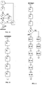
- This phase COMMON is common to all the different phases which shall be described later, and shall therefore be indicated only once.
- the MCU unit initially sets at a phase 1, where the arrival of a cell is recognized and in which the values of OCI, Cell Type and BAND_REQ values are read.
- the MCU unit sets at a phase 2. for the reading of the POSIZ value of the memory MAIN_MEMORY.
- the MCU unit sets then at a test phase 3., in which it is checked if the node in AN position.
- the MCU unit sets at a phase 3.1. where the CH value is acquired. This CH value has a meaning only for AN nodes.
- the MCU unit sets at a test phase 4., where compatibility between the type of message received and the position (possibly associated to the status) in which the node is, is checked.
- test 3. be not successful, the MCU unit, directly goes to the test 4. phase, skipping phase 3.1.
- test 4. has a negative result
- the MCU unit sets at a phase 4.1. in which an appropriate error signal is generated and the MCU units returns to phase 1. waiting for a next cell.
- the MCU unit While if test 4. is successful, the MCU unit quits the COMMON phase and goes on with differentiate processing phases according to the type of cell, to the role of the switching node ATM to which the server FRMU is connected playes for that connection and, in the case of node AN, to the status indicated by the field CH.
- the procedure accomplished by the server FRMU shall now be described in the case the switching node ATM to which the server itself is connected, is the access node AN and in which the cell identified in the COMMON phase is a Reservation Request type cell.
- the MCU unit sets at a phase 5. where the OVL value of the memory MAIN_MEMORY is read.
- the MCU unit sets at phase 6. in which a Reservation Received type cell is sent toward the user network CPN.
- the MCU unit sets at phase 7. in which the value of the BAND_DISP field is read by the memory OUTPUT_MEMORY.
- the MCU unit sets at test phase 8. where it is checked if the BAND_DISP value is higher than the BAND_REQ value.
- the MCU unit sets at a phase 8.1.2 where a value equal to the difference between the BAND_DISP value and the BAND_REQ value is written inside the memory OUTPUT_MEMORY.
- the MASK2 value represents therefore the time instant when the timer T2 shall be over (answer stand by).
- the MCU unit sets at a phase 8.1.4 in which values MASK2, BAND_REQ and OCI values calculated before are written in the memory TIMING_MEMORY.
- the MCU unit sets at a phase 8.1.5 in which a value indicating the access address to the memory location TIMING_MEMORY containing the information MASK2, is written inside the IND field of the memory MAIN_MEMORY. Whenever the bandwidth allocation request has positive result by the subsequent nodes, this IND field shall allow to find the location of timer to cancel in the memory TIMING_MEMORY.
- the MCU unit sets at phase 8.2.1 in which a "waiting call" indication is written inside the CH field of the memory MAIN_MEMORY and the value of the CONT field containing the number of new attempts is increased by one unit.
- the MASK1 value represents therefore the time instant in which the timer T1 shall be over (interval among new attempts).
- the MCU sets at phase 8.2.3 in which values MASK1, BAND_REQ and OCI values previously calculated are written inside the memory TIMING_MEMORY.
- the MCU unit sets at phase 5. where the IND value is read from the memory MAIN_MEMORY.
- the MCU unit sets at phase 6. in which the timer T2 is reset.
- the MCU unit sets at phase 7. in which an indication of "stable call" is written inside the field CH of the memory MAIN_MEMORY and the BCV value of the bandwidth associated to this call is updated.
- the MCU unit sets at phase 8 during which a reservation accepted cell is sent toward the user network CPN.
- the MCU unit sets at phase 9 in which an Updating cell is sent toward the devices performing the policing functions PF.
- the MCU unit sets at phase 5. in which the values contained in fields CONT and OVL of the memory MAIN_MEMORY are read.
- the MCU unit sets at the test phase 6. in which it is checked if the CONT value is lower than a maximum value MAX and where the timer T2 is reset.
- the MCU unit sets at phase 6.1.1. where an indication of "waiting call" is written inside the field CH of the memory MAIN_MEMORY and the value of the field CONT containing the number of new attempts is increased by one unit.
- the MASK1 value represents therefore the time instant on which the timer T1 shall be over (interval among new attempts).
- the MCU sets at phase 6.1.3 in which values MASK1, BAND_REQ and OCI values, previously calculated are written inside the memory TIMING_MEMORY.
- the MCU unit sets at phase 6.2.1. in which an indication of "stable call" is written-inside the field CH of the memory MAIN_MEMORY and the value of the CONT field containing the number of new attempts is reset.
- the MCU unit sets at phase 6.2.2 in which a Reservation Denied Cell is sent toward the user network CPN.
- the MCU unit sets at phase 5. in which the value contained in field OVL of the memory MAIN_MEMORY is read.
- the MCU unit sets at phase 6, where an indication of "call release” indication is written inside the CH field of the memory MAIN_MEMORY and the BVC value of the bandwidth associated to this call is updated.
- the MCU unit sets at phase 7. in which the updated value of the available bandwidth on the output link is written inside the memory OUTPUT_MEMORY.
- the output memory sets at phase 8. where a Release Request cell is sent toward the subsequent node.
- the MCU unit sets at phase 9. where an Updating cell is sent toward the policing devices PF.
- the MASK2 value represents therefore the time instant on which the timer T2 shall be over (answer stand by).
- the MCU sets at phase 11 in which values MASK2, BAND_REQ and OCI values, previously calculated are written inside the memory TIMING_MEMORY.
- the MCU unit sets at phase 12 in which a value indicating the access at TIMING_MEMORY location containing said MASK2 information is written inside the field IND.
- the MCU unit sets at phase 5. in which the value contained in field IND of the memory MAIN_MEMORY is read.
- the MCU unit sets at phase 5. in which the OVL value is read in the MAIN_MEMORY.
- the MCU unit sets at phase 6, where the BAND_DISP field value is read in the OUTPUT_MEMORY.
- the MCU unit sets at test phase 7. where it is checked if the BAND_DISP value is higher than the BAND_REQ value.
- the MCU unit sets at phase 7.1.1. in which the updating of the value of the bandwidth associated to the call is written inside the BVC field of the MAIN_MEMORY.
- the MCU unit sets at phase 7.1.2, where a value equal to the difference between BAND_DISP and the value BAND_REQ is written inside the OUTPUT_MEMORY.
- test 7. if test 7. is not successful, the MCU unit sets at a phase 7.2.1. in which a Reservation Denied cell is sent toward the previous node.
- the MCU unit sets at phase 5. in which a Reservation Accepted cell is sent toward the previous node.
- the MCU unit sets at phase 5. in which the value contained in the field OVL of the memory MAIN_MEMORY is read.
- the MCU unit sets at phase 6. in which the indication of the bandwidth associated to the call is written inside the BVC field, restoring the value preceding this unsuccessful reservation attempt.
- the MCU unit sets at phase 7. where the updated value of BAND_DISP is written inside the memory OUTPUT_MEMORY restoring the previous value, read in one of the information fields of the Reservation Denied cell.
- the MCU unit sets at phase 5. in which the value contained in the field OVL of the memory MAIN_MEMORY is read.
- the MCU unit sets at phase 6. in which the indication of the new value of the bandwidth associated to the call is written inside the BVC field of the MAIN_MEMORY.
- the MCU unit sets at phase 7. where the updated value of available bandwidth on the output link is written inside the memory OUTPUT_MEMORY, adding the bandwidth released with this operation.
- the MCU unit sets at phase 5. in which a Release Completed cell is sent toward the previous node.
- the EN node Whenever the FRM protocol is terminated by the destination user network CPN and not by the EN node, the EN node operates just as one of the TN nodes.
- the MCU unit sets at phase 5. in which the OVL value of the memory MAIN_MEMORY is read.
- the MCU unit sets at phase 6. in which the indication of the value of the field BAND_DISP is read by the OUTPUT_MEMORY.
- the MCU unit sets at phase 7. where the BAND_DISP value is checked to be higher than the BAND_REQ one.
- the MCU unit sets at phase 7.1.1 in which a value equal to the difference between the BAND_DISP value and the BAND_REQ value is written inside the OUTPUT_MEMORY.
- the MCU unit sets at phase 7.1.2. in which the content of the BVC field of the memory MAIN_MEMORY is updated and sent toward the previous node a Reservation Accepted cell.
- the MCU unit sets at phase 5. in which the OVL value of the memory MAIN_MEMORY is read.
- the MCU unit sets at phase 6. in which the updated value of BAND_DISP relevant to that connection is written in the OUTPUT_MEMORY.
- the MCU unit sets at phase 7. where the BVC field of the MAIN_MEMORY is updated subtracting the value of bandwidth released.
- the MCU unit sets at phase 8. in which a Release Completed cell is sent towards the previous node.
- policing functions PF must be performed only in the access node AN and not in transit nodes TN and in the final node EN.
- the performance of all the phases forming the method according to the present invention are carried out at FRM protocol level. Being the FRM protocol an ATM level protocol, all the operations are carried out with high effectiveness and speed.
- FRMU servers treat a very reduced cell flow.
- FRMU servers can be realized with simple and low cost devices.
- a typical server FRMU for an access node of average dimension could be realized using an ordinary Personal Computer.
Applications Claiming Priority (2)
| Application Number | Priority Date | Filing Date | Title |
|---|---|---|---|
| ITMI941481A IT1271667B (it) | 1994-07-14 | 1994-07-14 | Metodo ed apparecchiatura per la gestione in tempo reale delle risorse in una rete privata virturale in tecnica atm |
| ITMI941481 | 1994-07-14 |
Publications (3)
| Publication Number | Publication Date |
|---|---|
| EP0692892A2 true EP0692892A2 (de) | 1996-01-17 |
| EP0692892A3 EP0692892A3 (de) | 1998-07-22 |
| EP0692892B1 EP0692892B1 (de) | 2003-04-16 |
Family
ID=11369286
Family Applications (1)
| Application Number | Title | Priority Date | Filing Date |
|---|---|---|---|
| EP95201884A Expired - Lifetime EP0692892B1 (de) | 1994-07-14 | 1995-07-10 | Verfahren und Ausrüstung zur Echtzeitverwaltung von Kommunikationsmitteln in einem virtuellen Privatnetz in ATM-Technik |
Country Status (3)
| Country | Link |
|---|---|
| EP (1) | EP0692892B1 (de) |
| DE (1) | DE69530340T2 (de) |
| IT (1) | IT1271667B (de) |
Cited By (4)
| Publication number | Priority date | Publication date | Assignee | Title |
|---|---|---|---|---|
| WO1999007117A1 (en) * | 1997-08-04 | 1999-02-11 | At & T Corp. | Improved acknowledgment of bandwidth requests for the block transfer of data |
| DE10021502A1 (de) * | 2000-05-03 | 2001-11-08 | Siemens Ag | Verfahren zum Sichern der Dienstgüte von Verbindungen zwischen Teilbereichen eines paketorientierten Netzes mit einem Ressourcemanager |
| US8116203B2 (en) | 2001-07-23 | 2012-02-14 | Broadcom Corporation | Multiple virtual channels for use in network devices |
| US8750320B2 (en) | 1997-01-23 | 2014-06-10 | Broadcom Corporation | Fibre channel arbitrated loop bufferless switch circuitry to increase bandwidth without significant increase in cost |
Families Citing this family (6)
| Publication number | Priority date | Publication date | Assignee | Title |
|---|---|---|---|---|
| US7295555B2 (en) | 2002-03-08 | 2007-11-13 | Broadcom Corporation | System and method for identifying upper layer protocol message boundaries |
| US7346701B2 (en) | 2002-08-30 | 2008-03-18 | Broadcom Corporation | System and method for TCP offload |
| US7411959B2 (en) | 2002-08-30 | 2008-08-12 | Broadcom Corporation | System and method for handling out-of-order frames |
| US7934021B2 (en) | 2002-08-29 | 2011-04-26 | Broadcom Corporation | System and method for network interfacing |
| US8180928B2 (en) | 2002-08-30 | 2012-05-15 | Broadcom Corporation | Method and system for supporting read operations with CRC for iSCSI and iSCSI chimney |
| US7313623B2 (en) | 2002-08-30 | 2007-12-25 | Broadcom Corporation | System and method for TCP/IP offload independent of bandwidth delay product |
Family Cites Families (3)
| Publication number | Priority date | Publication date | Assignee | Title |
|---|---|---|---|---|
| DE69030037T2 (de) * | 1989-08-15 | 1997-06-26 | At & T Corp | Verfahren zur Verkehrsregelung in einem Hochgeschwindigkeitsdatennetz |
| CA2038646C (en) * | 1990-03-20 | 1995-02-07 | Katsumi Oomuro | Atm communication system with optimal traffic control by changing the allocated bandwidth |
| JPH04229747A (ja) * | 1990-08-17 | 1992-08-19 | Hitachi Ltd | パケット交換方法、およびパケット交換システム |
-
1994
- 1994-07-14 IT ITMI941481A patent/IT1271667B/it active IP Right Grant
-
1995
- 1995-07-10 EP EP95201884A patent/EP0692892B1/de not_active Expired - Lifetime
- 1995-07-10 DE DE69530340T patent/DE69530340T2/de not_active Expired - Fee Related
Non-Patent Citations (1)
| Title |
|---|
| None |
Cited By (6)
| Publication number | Priority date | Publication date | Assignee | Title |
|---|---|---|---|---|
| US8750320B2 (en) | 1997-01-23 | 2014-06-10 | Broadcom Corporation | Fibre channel arbitrated loop bufferless switch circuitry to increase bandwidth without significant increase in cost |
| WO1999007117A1 (en) * | 1997-08-04 | 1999-02-11 | At & T Corp. | Improved acknowledgment of bandwidth requests for the block transfer of data |
| DE10021502A1 (de) * | 2000-05-03 | 2001-11-08 | Siemens Ag | Verfahren zum Sichern der Dienstgüte von Verbindungen zwischen Teilbereichen eines paketorientierten Netzes mit einem Ressourcemanager |
| US7126919B2 (en) | 2000-05-03 | 2006-10-24 | Siemens Aktiengesellschaft | Method for assuring the quality of service of connections between subregions of a packet-oriented network having a resource manager |
| US8116203B2 (en) | 2001-07-23 | 2012-02-14 | Broadcom Corporation | Multiple virtual channels for use in network devices |
| US8493857B2 (en) | 2001-07-23 | 2013-07-23 | Broadcom Corporation | Multiple logical channels for use in network devices |
Also Published As
| Publication number | Publication date |
|---|---|
| ITMI941481A0 (it) | 1994-07-14 |
| DE69530340T2 (de) | 2004-03-04 |
| ITMI941481A1 (it) | 1996-01-14 |
| IT1271667B (it) | 1997-06-04 |
| EP0692892B1 (de) | 2003-04-16 |
| DE69530340D1 (de) | 2003-05-22 |
| EP0692892A3 (de) | 1998-07-22 |
Similar Documents
| Publication | Publication Date | Title |
|---|---|---|
| US5784358A (en) | Broadband switching network with automatic bandwidth allocation in response to data cell detection | |
| CA2184830C (en) | Broadband switching network | |
| US6442138B1 (en) | Method and apparatus for controlling admission of connection requests | |
| EP1235461B1 (de) | Verfahren zur Zugangssteuerung und Lenkung von Virtuelle Verbindungen | |
| AU718665B2 (en) | Broadband switching system | |
| EP0522391B1 (de) | Wiederzuteilung der Betriebsmittel für einen erzwungenen Benutzerverkehrsfluss | |
| US6707820B1 (en) | Virtual circuit network dynamic channel management | |
| EP0487235B1 (de) | Bandbreitenverwaltung und Überlastabwehr für den Zugang zu Breitband-ISDN-Netzen | |
| US7035211B1 (en) | Broadband switching network | |
| US6452905B1 (en) | Broadband switching system | |
| EP0847221A2 (de) | Steuerungsvorrichtung für ein ATM-Netzwerk | |
| US6282197B1 (en) | ATM switching apparatus and ATM communications network | |
| JP3211880B2 (ja) | 帯域制御方式 | |
| US5699345A (en) | Congestion control method in asynchronous transfer mode local area network | |
| EP0692892B1 (de) | Verfahren und Ausrüstung zur Echtzeitverwaltung von Kommunikationsmitteln in einem virtuellen Privatnetz in ATM-Technik | |
| CA2276681A1 (en) | Subscriber permissions and restrictions for switched connections in a communications network | |
| JP3457522B2 (ja) | パケット通信方法 | |
| EP0884923B1 (de) | Paketvermittlungsnetzwerk, Paketvermittlungseinrichtung und Netzwerkmanagementeinrichtung | |
| US7480239B1 (en) | Method and apparatus for true priority based connection establishment within a PNNI ATM network | |
| Burgin | Management of capacity and control in broadband ISDN | |
| US5982751A (en) | Rare probability connection call registration method using payload type indication field information for asynchronous transfer mode switching system | |
| JP3617868B2 (ja) | ノード装置及び網リソース予約方法 | |
| KR100241885B1 (ko) | 에이티엠 교환망의 소프트 피브이씨 구현 방법 | |
| WO2000060897A1 (en) | Modification of signalling resources in a communications system | |
| JPH08256152A (ja) | Atmユーザ構内網の呼処理制御方法 |
Legal Events
| Date | Code | Title | Description |
|---|---|---|---|
| PUAI | Public reference made under article 153(3) epc to a published international application that has entered the european phase |
Free format text: ORIGINAL CODE: 0009012 |
|
| AK | Designated contracting states |
Kind code of ref document: A2 Designated state(s): DE FR NL SE |
|
| PUAL | Search report despatched |
Free format text: ORIGINAL CODE: 0009013 |
|
| AK | Designated contracting states |
Kind code of ref document: A3 Designated state(s): DE FR NL SE |
|
| 17P | Request for examination filed |
Effective date: 19990129 |
|
| 17Q | First examination report despatched |
Effective date: 20011010 |
|
| GRAG | Despatch of communication of intention to grant |
Free format text: ORIGINAL CODE: EPIDOS AGRA |
|
| GRAG | Despatch of communication of intention to grant |
Free format text: ORIGINAL CODE: EPIDOS AGRA |
|
| GRAH | Despatch of communication of intention to grant a patent |
Free format text: ORIGINAL CODE: EPIDOS IGRA |
|
| GRAH | Despatch of communication of intention to grant a patent |
Free format text: ORIGINAL CODE: EPIDOS IGRA |
|
| RAP1 | Party data changed (applicant data changed or rights of an application transferred) |
Owner name: SIEMENS MOBILE COMMUNICATIONS S.P.A. Owner name: ITALTEL S.P.A. |
|
| GRAA | (expected) grant |
Free format text: ORIGINAL CODE: 0009210 |
|
| AK | Designated contracting states |
Designated state(s): DE FR NL SE |
|
| REF | Corresponds to: |
Ref document number: 69530340 Country of ref document: DE Date of ref document: 20030522 Kind code of ref document: P |
|
| REG | Reference to a national code |
Ref country code: SE Ref legal event code: TRGR |
|
| ET | Fr: translation filed | ||
| PLBE | No opposition filed within time limit |
Free format text: ORIGINAL CODE: 0009261 |
|
| STAA | Information on the status of an ep patent application or granted ep patent |
Free format text: STATUS: NO OPPOSITION FILED WITHIN TIME LIMIT |
|
| 26N | No opposition filed |
Effective date: 20040119 |
|
| PGFP | Annual fee paid to national office [announced via postgrant information from national office to epo] |
Ref country code: FR Payment date: 20090710 Year of fee payment: 15 |
|
| PGFP | Annual fee paid to national office [announced via postgrant information from national office to epo] |
Ref country code: SE Payment date: 20090708 Year of fee payment: 15 Ref country code: NL Payment date: 20090705 Year of fee payment: 15 Ref country code: DE Payment date: 20090702 Year of fee payment: 15 |
|
| REG | Reference to a national code |
Ref country code: NL Ref legal event code: V1 Effective date: 20110201 |
|
| REG | Reference to a national code |
Ref country code: FR Ref legal event code: ST Effective date: 20110331 |
|
| PG25 | Lapsed in a contracting state [announced via postgrant information from national office to epo] |
Ref country code: DE Free format text: LAPSE BECAUSE OF NON-PAYMENT OF DUE FEES Effective date: 20110201 |
|
| REG | Reference to a national code |
Ref country code: DE Ref legal event code: R119 Ref document number: 69530340 Country of ref document: DE Effective date: 20110201 |
|
| PG25 | Lapsed in a contracting state [announced via postgrant information from national office to epo] |
Ref country code: FR Free format text: LAPSE BECAUSE OF NON-PAYMENT OF DUE FEES Effective date: 20100802 Ref country code: NL Free format text: LAPSE BECAUSE OF NON-PAYMENT OF DUE FEES Effective date: 20110201 |
|
| PG25 | Lapsed in a contracting state [announced via postgrant information from national office to epo] |
Ref country code: SE Free format text: LAPSE BECAUSE OF NON-PAYMENT OF DUE FEES Effective date: 20100711 |