EP0692862A2 - Energieversorgung für den Stator einer mehrphasigen Reluktanzmaschine - Google Patents
Energieversorgung für den Stator einer mehrphasigen Reluktanzmaschine Download PDFInfo
- Publication number
- EP0692862A2 EP0692862A2 EP95304742A EP95304742A EP0692862A2 EP 0692862 A2 EP0692862 A2 EP 0692862A2 EP 95304742 A EP95304742 A EP 95304742A EP 95304742 A EP95304742 A EP 95304742A EP 0692862 A2 EP0692862 A2 EP 0692862A2
- Authority
- EP
- European Patent Office
- Prior art keywords
- phase
- stator
- switch means
- nodes
- units
- Prior art date
- Legal status (The legal status is an assumption and is not a legal conclusion. Google has not performed a legal analysis and makes no representation as to the accuracy of the status listed.)
- Granted
Links
- 238000004804 winding Methods 0.000 claims abstract description 44
- 239000003990 capacitor Substances 0.000 claims description 16
- 230000004907 flux Effects 0.000 claims description 14
- 238000000034 method Methods 0.000 claims description 10
- 230000000977 initiatory effect Effects 0.000 claims description 4
- 230000000694 effects Effects 0.000 claims description 2
- 125000004122 cyclic group Chemical group 0.000 claims 1
- 238000010586 diagram Methods 0.000 description 6
- 239000004065 semiconductor Substances 0.000 description 6
- 230000008901 benefit Effects 0.000 description 5
- 230000003247 decreasing effect Effects 0.000 description 5
- 239000008186 active pharmaceutical agent Substances 0.000 description 4
- 230000003134 recirculating effect Effects 0.000 description 2
- 230000005534 acoustic noise Effects 0.000 description 1
- 230000007423 decrease Effects 0.000 description 1
- 238000007789 sealing Methods 0.000 description 1
Images

Classifications
-
- H—ELECTRICITY
- H02—GENERATION; CONVERSION OR DISTRIBUTION OF ELECTRIC POWER
- H02K—DYNAMO-ELECTRIC MACHINES
- H02K19/00—Synchronous motors or generators
- H02K19/02—Synchronous motors
- H02K19/10—Synchronous motors for multi-phase current
-
- H—ELECTRICITY
- H02—GENERATION; CONVERSION OR DISTRIBUTION OF ELECTRIC POWER
- H02P—CONTROL OR REGULATION OF ELECTRIC MOTORS, ELECTRIC GENERATORS OR DYNAMO-ELECTRIC CONVERTERS; CONTROLLING TRANSFORMERS, REACTORS OR CHOKE COILS
- H02P9/00—Arrangements for controlling electric generators for the purpose of obtaining a desired output
- H02P9/40—Arrangements for controlling electric generators for the purpose of obtaining a desired output by variation of reluctance of magnetic circuit of generator
-
- H—ELECTRICITY
- H02—GENERATION; CONVERSION OR DISTRIBUTION OF ELECTRIC POWER
- H02K—DYNAMO-ELECTRIC MACHINES
- H02K3/00—Details of windings
- H02K3/04—Windings characterised by the conductor shape, form or construction, e.g. with bar conductors
- H02K3/28—Layout of windings or of connections between windings
-
- H—ELECTRICITY
- H02—GENERATION; CONVERSION OR DISTRIBUTION OF ELECTRIC POWER
- H02P—CONTROL OR REGULATION OF ELECTRIC MOTORS, ELECTRIC GENERATORS OR DYNAMO-ELECTRIC CONVERTERS; CONTROLLING TRANSFORMERS, REACTORS OR CHOKE COILS
- H02P3/00—Arrangements for stopping or slowing electric motors, generators, or dynamo-electric converters
- H02P3/06—Arrangements for stopping or slowing electric motors, generators, or dynamo-electric converters for stopping or slowing an individual dynamo-electric motor or dynamo-electric converter
- H02P3/065—Arrangements for stopping or slowing electric motors, generators, or dynamo-electric converters for stopping or slowing an individual dynamo-electric motor or dynamo-electric converter for stopping or slowing a reluctance motor
-
- H—ELECTRICITY
- H02—GENERATION; CONVERSION OR DISTRIBUTION OF ELECTRIC POWER
- H02K—DYNAMO-ELECTRIC MACHINES
- H02K19/00—Synchronous motors or generators
- H02K19/02—Synchronous motors
- H02K19/10—Synchronous motors for multi-phase current
- H02K19/103—Motors having windings on the stator and a variable reluctance soft-iron rotor without windings
-
- H—ELECTRICITY
- H02—GENERATION; CONVERSION OR DISTRIBUTION OF ELECTRIC POWER
- H02P—CONTROL OR REGULATION OF ELECTRIC MOTORS, ELECTRIC GENERATORS OR DYNAMO-ELECTRIC CONVERTERS; CONTROLLING TRANSFORMERS, REACTORS OR CHOKE COILS
- H02P9/00—Arrangements for controlling electric generators for the purpose of obtaining a desired output
- H02P9/02—Details of the control
Definitions
- This invention relates to polyphase reluctance machines.
- a polyphase switched reluctance machine running either as a motor or a generator, normally has two electrical connections for each phase between the switching circuitry and each phase winding.
- Other connection schemes have been proposed, where two or more phases have one connection in common. In these cases the number of electrical connections will be fewer than twice the number of phases but never as few as the number of phases itself. Examples of prior art which illustrate the number of connections required by a switched reluctance machine are illustrated in Figures 1 to 3.
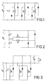
- FIG. 1 shows a typical converter circuit in which a three-phase switched reluctance motor is chosen for the purposes of illustration.
- Six electrical connections are required to the motor, shown at the ends of the motor phase windings 11,12 and 13.
- Energy is injected into a winding when both switches at the ends of each winding conduct together.
- Energy is returned from the winding to the dc supply 1 and its dc link capacitor 2 when the two diodes associated with each pair of switches conduct. If one switch and one diode of a phase conduct together, no energy flows to or from the dc supply - this is known as 'freewheeling'.
- stator may be in a different environment from the cables and there will then be a cost associated with the sealing of each cable entry to the environment.
- Figure 2 shows a converter circuit which may be used on a switched reluctance motor having an even number of phases.
- This circuit requires n+1 electrical terminals for n phases.
- a given phase receives energy from one of the capacitors 2,3 and from the dc supply when its switch conducts, and returns energy to the other capacitor and to the dc supply when its diode conducts.
- Figure 3 shows a converter circuit for a three-phase switched reluctance machine having four electrical terminals, one of which is common to all three phases.
- a switch e.g. in the form of a transistor
- its phase receives energy from the dc supply 1 and its capacitor 2 but when its diode conducts the phase returns energy to the capacitor 3 and the resistor 4.
- the energy returned to the capacitor 3, instead of being dissipated in the resistor 4 may be transferred by an additional switching circuit to the dc supply 1 and its capacitor 2.
- the invention applies to machines having two or more phases where, at most, only a respectively corresponding number of cables are required according to the invention.
- a polyphase reluctance machine comprising a rotor, a stator, a phase winding for each phase of the machine, and at least one uni-directional current device connected in series with each phase winding to form a phase unit therewith, the phase units being arranged in at least one conducting ring defining nodes at connections between the phase units.
- Each phase winding of a switched reluctance machine has a uni-directional current device connected in series with it to form the phase unit.
- Two or more phase units are connected in series to form a closed ring in which the conducting directions of the uni-directional current devices allow a current to circulate around the ring.
- Electrical supply connections to the machine are made at each of the nodes where one phase unit is connected to its neighbour, thus requiring the same number of supply cables as there are phase units.
- a two-phase motor has two phase units with two cable connections.
- a three-phase motor has three phase units connected in a delta configuration with three cable connections to the corners (constituting the nodes) of the delta.
- a four-phase motor has four phase units connected in a four-node configuration with four cable connections to the nodes.
- the uni-directional current device is a diode.
- the device may be arranged on one side of its respective phase winding and a further device may be connected to conduct in the same direction on the other side of the same phase winding.
- pairs of commonly connected uni-directional current devices at one of the nodes are formed in a single device package.
- the machine comprises n phases (n>3) and m conducting rings, where m is an integer never greater than n/2 and never less than 2.
- the m conducting rings may each comprise at least two phase units and may comprise up to n/2 units (n even) or (n+1)/2 units (n odd). Where two or more conducting rings comprise the same number of phase units, their respective nodes may be supplied by the same cable or by separate cables, thus being able to reduce the number of cables to the number of phase units in a conducting ring. When the conducting rings comprise different numbers of phase units, the total number of cables required is still equal to the number of phases.
- the phases of a four-phase motor may be taken in pairs and each pair of phases connected as for a two-phase motor.
- the invention is equally applicable to machines with more than four phases, for which the phase units may be configured in a polygon with cable connections to the respective nodes, or in a number of rings, such as deltas.
- a converter circuit for the machine includes switching circuits having a positive and a negative dc supply terminal, serially connected first and second switch means for each phase of the machine and means for transmitting electrical energy between each node of the conducting ring and the first and second switch means of the switching circuit, the pairs of serially connected switch means being connected across the positive and negative supply terminals.
- the means for transmitting electrical energy preferably comprises an electrically conductive line connected from between each of the first and second switch means, and supplying electrical energy to a respective one of the nodes.
- each of the first switch means connected with the positive supply terminal includes a diode connected across the said first switch means to conduct towards the positive supply terminal
- each of the second switch means connected with the negative supply terminal includes a diode connected across the said second switch means to conduct from the negative supply terminal
- the converter circuit for the machine includes a snubber capacitor connected across each of the switch means.
- the invention has the further benefit in that, in contrast to a conventional switched reluctance drive, where the cables of a phase carry a pulsating unidirectional current, the cables for a switched reluctance drive according to the invention carry equal alternating currents.
- This has a benefit compared with the circuits in Fig.2 or 3 in that the sum of the root mean squared (RMS) currents in the cables is less.
- RMS root mean squared
- a transformer can be interposed between the converter circuit and the nodes, i.e. in the cable connections carrying the power to the motor.
- these cables are unusually long, e.g.for a submersible pump operating in a very deep well, it is advantageous to design the motor for higher voltages than are convenient for the power converter so that the motor and its cables carry lower current at higher voltages than those occurring within the converter circuit, the step-up in voltage being performed by the transformer interposed between the converter and the cables supplying the motor.
- the method includes freewheeling the machine by oscillating the first or second switch means between on and off states repeatedly during the respective phase conduction cycle to reduce the average voltage applied to the phase windings.
- the supply voltage may be varied as a function of the speed of the motor.
- an inverter 8 is coupled to a three-phase switched reluctance machine 7 by only three electrical supply lines 10, 12 and 14.
- a 'motor' For the sake of convenience reference is made to a 'motor'.
- pairs of serially connected semiconductor switches S1/S6; S3/S2; S5/S4 are connected in parallel between positive and negative terminals of a supply voltage source V s .
- a dc link capacitor 16 is also connected across the positive and negative supply terminals.
- Each of the positive-side switches S1; S3; S5 has a recirculating diode D1; D3; D5 connected across it to conduct towards the positive supply terminal.
- Each of the negative-side switches S6; S2; S4 has a recirculating diode D6; D2; D4 connected across it to conduct from the negative supply terminal.
- Single diodes D1-D6 are shown. However, it will be appreciated by the skilled person that two or more diodes could be used, in place of each single diode shown, connected in parallel or in series.
- the three-phase motor 7 comprises three phase units, each comprising a phase winding RS; ST; TR and a serially connected phase diode DR; DS; DT.
- the phase diode may, in fact, each be a set of diodes connected in parallel.
- the phase units are connected in a delta configuration with each phase diode connected to conduct toward its winding.
- Each phase diode may be connected on the other side of its winding to equal effect.
- the diodes in the delta arrangement are thus arranged to allow current to circulate around the delta.
- the connections between the phase units define nodes R;S;T.
- the lines 10, 12 and 14 are each respectively connected between one of each of the nodes and the junction between the switches of one of the pairs of switches of the invertor.
- a motor with a plurality of phases can be split into groups (say a six-phase machine sub-divided into two delta groups, each delta having three phases).
- Each delta group may be fed by its own inverter such that there is still only one line per phase of the machine. Actuation of each of the separate inverters can be adjusted relative to the other. This then allows the control of the machine to reduce vibration, acoustic noise and output torque ripple because of the ability to shift the actuation of one set of phases relative to the other.
- the phase units of the machine in this embodiment comprise the winding/diode pairs RS/DR, ST/DS and TR/DT.
- the connections made to the nodes R, S and T are by cables to the output terminals R', S' and T' of the inverter 8.
- the inverter terminals R', S' and T' may be connected to the primary of a transformer 18 whose secondary is connected to the cables 10, 12, 14 supplying the motor through the nodes R, S and T.
- windings of the machine may be sequentially energised in synchronism with rotor rotation by control of the active semi-conductor switches S1-S6.
- Any type of semi-conductor or other switch capable of being turned on and off may be used in the circuit.
- the diodes D1-D6 provide for the continuation of current in a connecting cable or transformer winding when a semi-conductor switch of the associated phase is turned off.
- phase RS When one upper and one lower semi-conductor switch (as depicted in Fig.4) connected to different nodes of the delta ring of phase units are turned on together, e.g. S1 and S2, the phase RS is connected across the dc supply V s and flux will increase approximately linearly in the magnetic circuit associated with that phase winding. If S1 and S2 are both turned off, the current in the phase RS will transfer to D6 and D3. The polarity of the voltage across the phase RS reverses and the flux associated with the phase RS decreases approximately linearly. It should be noted that while diodes D6 and D3 conduct, a positive potential appears at node S of the motor and a negative potential appears at node R.
- the diodes DS and DT are forward biassed and current can increase in phases ST and TR, whilst diodes D3 and D6 remain conductive until current in the diodes DS and DT reaches equality with the currents in the diodes D3 and D6. Thereafter, the currents in RS, ST and TR, being equal, circulate around the delta connected phase units, eventually decaying to zero.
- the windings TR and RS are assumed to carry equal currents, with the current I RS increasing and the current I TR decreasing.
- the conduction of S1 and S2 causes I RS to increase, increasing the flux associated with the phase RS approximately linearly.
- the conduction of D4 and S1, demanded by the current in TR applies a reverse voltage -V s to TR, decreasing the flux therein approximately linearly.
- Table 1 summarises the conduction of switches S1-S6 and diodes D1-D6 with indications of current inequalities and flux variations. These refer to idealised conditions where the machine phase winding resistance and semiconductor volt-drop of the switches are ignored.
- the inverter circuit of Fig.5 offers the opportunity greatly to reduce the switch-off losses in the switches S1-S6.
- Like components are indicated by the corresponding numbering in Fig.4.
- the conducting lines 10, 12 and 14 are connected to their respective nodes as shown in Fig.4 with or without the transformer 18. Since with the conduction sequence of Table 1 the conduction of the diode, e.g. D2, always precedes the conduction of the switch, e.g. S2, it is possible to place snubber capacitors across each switch. This is illustrated by way of example by the snubber capacitors C connected in parallel across the switches S1-S6.
- a further embodiment of the invention is to use two diodes per phase unit, connected as shown in Fig.6.
- Each phase unit has a diode at each end of the phase winding, with both diodes arranged to conduct in the same direction as the original diode.
- This can have advantages in allowing the diodes to share the voltage across the phase unit on high voltage systems.
- adjacent diodes can be contained in a single module 20 as shown in Fig.6.
- machines such as reluctance machines can be constructed as linear motors in which the moving member is often referred to as a rotor.
- the term 'rotor' herein is intended to embrace such moving members of linear motors. Accordingly, the above description of several embodiments is made by way of example and not for purposes of limitation. The present invention is intended to be limited only by the spirit and scope of the following claims.
Landscapes
- Engineering & Computer Science (AREA)
- Power Engineering (AREA)
- Control Of Electric Motors In General (AREA)
- Synchronous Machinery (AREA)
- Control Of Ac Motors In General (AREA)
Applications Claiming Priority (2)
| Application Number | Priority Date | Filing Date | Title |
|---|---|---|---|
| GB9414116A GB9414116D0 (en) | 1994-07-13 | 1994-07-13 | Polyphase switched reluctance machines |
| GB9414116 | 1994-07-13 |
Publications (3)
| Publication Number | Publication Date |
|---|---|
| EP0692862A2 true EP0692862A2 (de) | 1996-01-17 |
| EP0692862A3 EP0692862A3 (de) | 1997-10-29 |
| EP0692862B1 EP0692862B1 (de) | 2003-04-02 |
Family
ID=10758253
Family Applications (1)
| Application Number | Title | Priority Date | Filing Date |
|---|---|---|---|
| EP95304742A Expired - Lifetime EP0692862B1 (de) | 1994-07-13 | 1995-07-06 | Energieversorgung für den Stator einer mehrphasigen Reluktanzmaschine |
Country Status (8)
| Country | Link |
|---|---|
| US (1) | US5703457A (de) |
| EP (1) | EP0692862B1 (de) |
| JP (1) | JPH08182383A (de) |
| KR (1) | KR960006213A (de) |
| CA (1) | CA2153526A1 (de) |
| DE (1) | DE69530147T2 (de) |
| GB (1) | GB9414116D0 (de) |
| TW (1) | TW342552B (de) |
Cited By (3)
| Publication number | Priority date | Publication date | Assignee | Title |
|---|---|---|---|---|
| FR2828030A1 (fr) * | 2001-07-30 | 2003-01-31 | Sagem | Procede de commande d'une machine a reluctance variable |
| CN106788119A (zh) * | 2017-03-14 | 2017-05-31 | 河北工业大学 | 一种永磁同步电机变频器及其应用方法 |
| WO2017191298A1 (en) * | 2016-05-04 | 2017-11-09 | Universiteit Gent | Switched reluctance machine and power converter |
Families Citing this family (26)
| Publication number | Priority date | Publication date | Assignee | Title |
|---|---|---|---|---|
| WO2006065988A2 (en) * | 2004-12-13 | 2006-06-22 | Borealis Technical Limited | Motor winding |
| US6838791B2 (en) * | 2000-11-15 | 2005-01-04 | Borealis Technical Limited | Mesh connected electrical rotating machine with span changing |
| EP0867853A3 (de) * | 1997-03-27 | 1998-12-23 | Hitachi, Ltd. | Schaltungsanordnung, Treiberschaltung und diese Komponente enthaltende Anzeigevorrichtung |
| GB9713136D0 (en) * | 1997-06-20 | 1997-08-27 | Switched Reluctance Drives Ltd | Switching circuit for a reluctance machine |
| US6137256A (en) * | 1998-11-10 | 2000-10-24 | Tridelta Industries, Inc. | Soft turn-off controller for switched reluctance machines |
| US7126298B2 (en) | 2000-10-23 | 2006-10-24 | Borealis Technical Limited | Mesh connected brake array for electrical rotating machines |
| US7928683B2 (en) | 2000-10-23 | 2011-04-19 | Borealis Technical Limited | High phase order AC machine with short pitch winding |
| US8198746B2 (en) * | 2000-11-15 | 2012-06-12 | Borealis Technical Limited | Chimney turbine |
| US20080042507A1 (en) * | 2000-11-15 | 2008-02-21 | Edelson Jonathan S | Turbine starter-generator |
| US6528964B2 (en) * | 2001-03-12 | 2003-03-04 | General Motors Corporation | Method and system of reducing turn-off loss and noise in a switched reluctance motor drive |
| US7201244B2 (en) * | 2003-10-03 | 2007-04-10 | Letourneau, Inc. | Vehicle for materials handling and other industrial uses |
| US20080054733A1 (en) * | 2004-05-12 | 2008-03-06 | Edelson Jonathan S | Slotless Ac Induction Motor |
| US20060273686A1 (en) * | 2004-06-21 | 2006-12-07 | Edelson Jonathan S | Hub motors |
| US9139294B2 (en) * | 2005-03-01 | 2015-09-22 | Borealis Technical Limited | Motor controller |
| KR100704482B1 (ko) * | 2005-04-01 | 2007-04-09 | 엘지전자 주식회사 | 저속 영역과 고속 영역에서의 발전 효율이 개선된 에스알발전기 |
| GB2440872B (en) * | 2005-04-19 | 2010-08-18 | Borealis Tech Ltd | Induction and switched reluctance motor |
| KR200408902Y1 (ko) * | 2005-12-05 | 2006-02-14 | 주식회사 인트론바이오테크놀로지 | 장갑형태의 핸드 팩용구 |
| AU2008321378B2 (en) * | 2007-11-13 | 2012-04-12 | Emerson Climate Technologies, Inc. | Three-phase detection module |
| US8729745B2 (en) * | 2010-10-25 | 2014-05-20 | Asm Assembly Automation Ltd | Multiple-phase linear switched reluctance motor |
| KR101534546B1 (ko) * | 2012-01-11 | 2015-07-07 | 니혼 덴산 가부시키가이샤 | 모터 제어기 |
| DE112013005863T5 (de) * | 2012-12-06 | 2015-08-20 | Nidec Corporation | Motorsteuerung |
| DE102014208747A1 (de) * | 2014-05-09 | 2015-11-12 | Robert Bosch Gmbh | Verfahren zum Wechsel eines Betriebszustands einer elektrischen Maschine und Vorrichtung zum Betriebszustandswechsel einer elektrischen Maschine |
| JP6451984B2 (ja) | 2014-12-26 | 2019-01-16 | 日本電産株式会社 | モータコントローラ |
| CN106100457A (zh) * | 2016-06-30 | 2016-11-09 | 冼毅 | 电容制动控制方法 |
| CN106100460A (zh) * | 2016-06-30 | 2016-11-09 | 冼毅 | 短接制动控制装置 |
| RU2662233C1 (ru) * | 2017-11-22 | 2018-07-25 | Общество с ограниченной ответственностью Научно-производственное предприятие "Резонанс" (ООО НПП "Резонанс") | Индукторная электрическая машина |
Citations (2)
| Publication number | Priority date | Publication date | Assignee | Title |
|---|---|---|---|---|
| EP0289425A1 (de) * | 1987-04-29 | 1988-11-02 | Valeo Equipements Electriques Moteur | Alternator mit einer induzierten Wicklung, die Gleichrichtkomponenten aufweist |
| JPH05219787A (ja) * | 1992-01-31 | 1993-08-27 | Brother Ind Ltd | 3相可変リラクタンスモータの駆動装置 |
Family Cites Families (7)
| Publication number | Priority date | Publication date | Assignee | Title |
|---|---|---|---|---|
| US3609492A (en) * | 1970-07-17 | 1971-09-28 | Sperry Rand Corp | Reversible brushless dc motor |
| US3678352A (en) * | 1970-11-06 | 1972-07-18 | Gen Electric | Compatible permanent magnet or reluctance brushless motors and controlled switch circuits |
| GB1604284A (en) * | 1978-05-26 | 1981-12-09 | Chloride Group Ltd | Variable reluctance motor systems |
| GB2037103B (en) * | 1978-05-26 | 1982-04-28 | Chloride Group Ltd | Variable reluctance motor systems |
| US4338557A (en) * | 1979-08-14 | 1982-07-06 | Wanlass Cravens Lamar | Variable speed electric machine having controlled magnetic flux density |
| US4445077A (en) * | 1982-01-25 | 1984-04-24 | Philips Kommunikations Industrie Ag | Drive circuit for step motor |
| US4983902A (en) * | 1989-11-01 | 1991-01-08 | Sundstrand Corporation | Fast current discharging switch for a variable reluctance motor drive |
-
1994
- 1994-07-13 GB GB9414116A patent/GB9414116D0/en active Pending
-
1995
- 1995-07-06 EP EP95304742A patent/EP0692862B1/de not_active Expired - Lifetime
- 1995-07-06 DE DE69530147T patent/DE69530147T2/de not_active Expired - Fee Related
- 1995-07-10 CA CA002153526A patent/CA2153526A1/en not_active Abandoned
- 1995-07-12 US US08/501,643 patent/US5703457A/en not_active Expired - Lifetime
- 1995-07-13 JP JP7199264A patent/JPH08182383A/ja active Pending
- 1995-07-13 KR KR1019950020654A patent/KR960006213A/ko not_active Application Discontinuation
- 1995-07-17 TW TW084107438A patent/TW342552B/zh active
Patent Citations (2)
| Publication number | Priority date | Publication date | Assignee | Title |
|---|---|---|---|---|
| EP0289425A1 (de) * | 1987-04-29 | 1988-11-02 | Valeo Equipements Electriques Moteur | Alternator mit einer induzierten Wicklung, die Gleichrichtkomponenten aufweist |
| JPH05219787A (ja) * | 1992-01-31 | 1993-08-27 | Brother Ind Ltd | 3相可変リラクタンスモータの駆動装置 |
Non-Patent Citations (1)
| Title |
|---|
| PATENT ABSTRACTS OF JAPAN vol. 017, no. 668 (E-1473) 09 December 1993 & JP 05 219 787 A (BROTHER IND LTD) 27 August 1993 * |
Cited By (5)
| Publication number | Priority date | Publication date | Assignee | Title |
|---|---|---|---|---|
| FR2828030A1 (fr) * | 2001-07-30 | 2003-01-31 | Sagem | Procede de commande d'une machine a reluctance variable |
| WO2003012973A1 (fr) * | 2001-07-30 | 2003-02-13 | Johnson Controls Automotive Electronics | Procede de commande d'une machine a reluctance variable |
| WO2017191298A1 (en) * | 2016-05-04 | 2017-11-09 | Universiteit Gent | Switched reluctance machine and power converter |
| US10491150B2 (en) | 2016-05-04 | 2019-11-26 | Universiteit Gent | Switched reluctance machine and power converter |
| CN106788119A (zh) * | 2017-03-14 | 2017-05-31 | 河北工业大学 | 一种永磁同步电机变频器及其应用方法 |
Also Published As
| Publication number | Publication date |
|---|---|
| DE69530147D1 (de) | 2003-05-08 |
| EP0692862B1 (de) | 2003-04-02 |
| KR960006213A (ko) | 1996-02-23 |
| EP0692862A3 (de) | 1997-10-29 |
| US5703457A (en) | 1997-12-30 |
| CA2153526A1 (en) | 1996-01-14 |
| TW342552B (en) | 1998-10-11 |
| GB9414116D0 (en) | 1994-08-31 |
| DE69530147T2 (de) | 2003-12-18 |
| JPH08182383A (ja) | 1996-07-12 |
Similar Documents
| Publication | Publication Date | Title |
|---|---|---|
| EP0692862B1 (de) | Energieversorgung für den Stator einer mehrphasigen Reluktanzmaschine | |
| EP0852425B1 (de) | Stromwandlervorrichtung und -verfahren | |
| CN107925366B (zh) | 嵌套式变换器 | |
| AU729691B2 (en) | Permanent magnet direct current (PMDC) machine with integral reconfigurable winding control | |
| US7026783B2 (en) | Drive system | |
| US5892677A (en) | Adaptive overlapping communication control of modular AC-AC converter and integration with device module of multiple AC-AC switches | |
| CN102511123B (zh) | 电力转换装置 | |
| US5666278A (en) | High voltage inverter utilizing low voltage power switches | |
| EP0188239B1 (de) | Leistungsversorgungseinrichtung für Reluktanzmotoren | |
| US7262982B2 (en) | Power conversion apparatus | |
| EP0088338A1 (de) | Wechselrichteranlage mit GTO-Thyristoren | |
| KR20080064162A (ko) | 전자 정류기 회로 | |
| US3887859A (en) | Self-commutating frequency converter with additional charging arrangement | |
| EP0752751A2 (de) | Schaltkreis für induktive Last | |
| US5025360A (en) | Inverter switch with parallel free-wheel diodes | |
| US5504410A (en) | Switching circuit | |
| US4609859A (en) | Induction motor drive circuits | |
| JP4153719B2 (ja) | 可変速駆動装置 | |
| US4716515A (en) | Switched capacitor induction motor drive | |
| EP0286267A2 (de) | Umformergespeiste Wechselstrommaschine ohne Dämpferwicklung | |
| JP3251802B2 (ja) | 直列多重電力変換装置 | |
| EP0752753B1 (de) | Leistungsschaltkreis für Reluktanzmaschine | |
| US4597039A (en) | Switched capacitor induction motor drive | |
| US4404512A (en) | Motor drive circuit | |
| US3984752A (en) | Electrical valve circuit apparatus |
Legal Events
| Date | Code | Title | Description |
|---|---|---|---|
| PUAI | Public reference made under article 153(3) epc to a published international application that has entered the european phase |
Free format text: ORIGINAL CODE: 0009012 |
|
| AK | Designated contracting states |
Kind code of ref document: A2 Designated state(s): DE ES FR GB IT NL SE |
|
| RAP1 | Party data changed (applicant data changed or rights of an application transferred) |
Owner name: SWITCHED RELUCTANCE DRIVES LIMITED |
|
| PUAL | Search report despatched |
Free format text: ORIGINAL CODE: 0009013 |
|
| AK | Designated contracting states |
Kind code of ref document: A3 Designated state(s): DE ES FR GB IT NL SE |
|
| 17P | Request for examination filed |
Effective date: 19980416 |
|
| 17Q | First examination report despatched |
Effective date: 19980702 |
|
| GRAH | Despatch of communication of intention to grant a patent |
Free format text: ORIGINAL CODE: EPIDOS IGRA |
|
| GRAH | Despatch of communication of intention to grant a patent |
Free format text: ORIGINAL CODE: EPIDOS IGRA |
|
| GRAA | (expected) grant |
Free format text: ORIGINAL CODE: 0009210 |
|
| AK | Designated contracting states |
Designated state(s): DE ES FR GB IT NL SE |
|
| PG25 | Lapsed in a contracting state [announced via postgrant information from national office to epo] |
Ref country code: NL Free format text: LAPSE BECAUSE OF FAILURE TO SUBMIT A TRANSLATION OF THE DESCRIPTION OR TO PAY THE FEE WITHIN THE PRESCRIBED TIME-LIMIT Effective date: 20030402 Ref country code: IT Free format text: LAPSE BECAUSE OF FAILURE TO SUBMIT A TRANSLATION OF THE DESCRIPTION OR TO PAY THE FEE WITHIN THE PRESCRIBED TIME-LIMIT;WARNING: LAPSES OF ITALIAN PATENTS WITH EFFECTIVE DATE BEFORE 2007 MAY HAVE OCCURRED AT ANY TIME BEFORE 2007. THE CORRECT EFFECTIVE DATE MAY BE DIFFERENT FROM THE ONE RECORDED. Effective date: 20030402 |
|
| REG | Reference to a national code |
Ref country code: GB Ref legal event code: FG4D |
|
| REF | Corresponds to: |
Ref document number: 69530147 Country of ref document: DE Date of ref document: 20030508 Kind code of ref document: P |
|
| PG25 | Lapsed in a contracting state [announced via postgrant information from national office to epo] |
Ref country code: SE Free format text: LAPSE BECAUSE OF FAILURE TO SUBMIT A TRANSLATION OF THE DESCRIPTION OR TO PAY THE FEE WITHIN THE PRESCRIBED TIME-LIMIT Effective date: 20030702 |
|
| NLV1 | Nl: lapsed or annulled due to failure to fulfill the requirements of art. 29p and 29m of the patents act | ||
| ET | Fr: translation filed | ||
| PG25 | Lapsed in a contracting state [announced via postgrant information from national office to epo] |
Ref country code: ES Free format text: LAPSE BECAUSE OF FAILURE TO SUBMIT A TRANSLATION OF THE DESCRIPTION OR TO PAY THE FEE WITHIN THE PRESCRIBED TIME-LIMIT Effective date: 20031030 |
|
| PLBE | No opposition filed within time limit |
Free format text: ORIGINAL CODE: 0009261 |
|
| STAA | Information on the status of an ep patent application or granted ep patent |
Free format text: STATUS: NO OPPOSITION FILED WITHIN TIME LIMIT |
|
| 26N | No opposition filed |
Effective date: 20040105 |
|
| PGFP | Annual fee paid to national office [announced via postgrant information from national office to epo] |
Ref country code: DE Payment date: 20050630 Year of fee payment: 11 |
|
| PGFP | Annual fee paid to national office [announced via postgrant information from national office to epo] |
Ref country code: FR Payment date: 20050708 Year of fee payment: 11 |
|
| PG25 | Lapsed in a contracting state [announced via postgrant information from national office to epo] |
Ref country code: DE Free format text: LAPSE BECAUSE OF NON-PAYMENT OF DUE FEES Effective date: 20070201 |
|
| REG | Reference to a national code |
Ref country code: FR Ref legal event code: ST Effective date: 20070330 |
|
| PG25 | Lapsed in a contracting state [announced via postgrant information from national office to epo] |
Ref country code: FR Free format text: LAPSE BECAUSE OF NON-PAYMENT OF DUE FEES Effective date: 20060731 |
|
| PGFP | Annual fee paid to national office [announced via postgrant information from national office to epo] |
Ref country code: GB Payment date: 20140703 Year of fee payment: 20 |
|
| REG | Reference to a national code |
Ref country code: GB Ref legal event code: PE20 Expiry date: 20150705 |
|
| PG25 | Lapsed in a contracting state [announced via postgrant information from national office to epo] |
Ref country code: GB Free format text: LAPSE BECAUSE OF EXPIRATION OF PROTECTION Effective date: 20150705 |