EP0692193B1 - Method and apparatus for aligning labels on shirred food casings - Google Patents
Method and apparatus for aligning labels on shirred food casings Download PDFInfo
- Publication number
- EP0692193B1 EP0692193B1 EP94114784A EP94114784A EP0692193B1 EP 0692193 B1 EP0692193 B1 EP 0692193B1 EP 94114784 A EP94114784 A EP 94114784A EP 94114784 A EP94114784 A EP 94114784A EP 0692193 B1 EP0692193 B1 EP 0692193B1
- Authority
- EP
- European Patent Office
- Prior art keywords
- casing
- eye
- portions
- sensing
- casings
- Prior art date
- Legal status (The legal status is an assumption and is not a legal conclusion. Google has not performed a legal analysis and makes no representation as to the accuracy of the status listed.)
- Expired - Lifetime
Links
Images


Classifications
-
- A—HUMAN NECESSITIES
- A22—BUTCHERING; MEAT TREATMENT; PROCESSING POULTRY OR FISH
- A22C—PROCESSING MEAT, POULTRY, OR FISH
- A22C11/00—Sausage making ; Apparatus for handling or conveying sausage products during manufacture
- A22C11/02—Sausage filling or stuffing machines
Definitions
- the invention relates generally to the control of a machine for automatically sizing and filling food casings, and, more particularly, to a method and apparatus for aligning labels on shirred food casings as the casings are being filled and clipped.
- Chub packages are typically made of fibrous material, polyethylene film, saran film, or a combination of polyethylene film and saran film.
- the film is typically stored on a roll, and is shirred into strands prior to filling.
- two or more plies of film are used, and at least one ply is imprinted with information about the product.
- the film functions both as a package and as a permanent label for the product.
- the shirred casing strands are placed on the stuffing horn and sizing ring of an automatic sizing and stuffing machine.
- the leading end of the first casing is clipped closed and food, in the form of an emulsion, is pumped through the stuffing horn.
- food in the form of an emulsion
- the shirred casing is pulled off the stuffing horn by the force of the food flow.
- Each casing is clipped to make individual chub packages. It is desirable that the imprinted label be centered between the end clips of each filled casing.
- United States Patent No. 4,580,316 discloses a machine for automatically manufacturing shirred sausage casings which includes means for measuring register marks on the casings.
- the shirred casings of this invention do not include imprinted labels and hence there is no problem of interference between the register marks and a label.
- United States Patent No. 4,625,362 discloses a method and device for automated manufacture of strings of sausages which incorporates a photocell for sensing sealing joints in shirred casings.
- the shirred casings of this invention are not imprinted with labels, and hence there is no interference problem between the sealing joints and the labels.
- the invention relates to a method for the continuous automated manufacture of stuffed food casings containing imprinted labels, wherein tubular material for the casings from a supply source is axially shirred into sections and the sections are stuffed with food emulsion into divided off portions, characterized by: measuring linear motion of the casing as the portions are filled with food emulsion; inputting the measured motion to a programmable logic controller; within the programmable logic controller, calculating an approximate distance between eye-mark bars separating the individual portions, where the calculation is based upon a known distance between eye-mark bars; based upon the calculated approximate distance and the measured motion, selectively sensing eye-mark bars which separate individual casings while ignoring printed label material between eye-mark bars; and, clipping individual sections of the casing closed at precise locations in response to the sensing of eye-mark bars to accurately position the labels between end-clips secured to ends of each of the portions.
- An apparatus operatively arranged to implement the method of the invention is also provided.
- a primary object of the invention is to provide a method and apparatus for centering labels between endclips of filled food casings.
- a secondary object is to provide a method and apparatus for centering labels between ends of filled food casings which does not require precise placement of the casing on a horn ring of a filling machine.
- the invention relates to a method for the continuous automated manufacture of stuffed food casings containing imprinted labels, wherein tubular material for the casings from a supply source is axially shirred into sections and the sections are stuffed with food emulsion into divided off portions, characterized by: measuring linear motion of the casing as the portions are filled with food emulsion; inputting the measured motion to a programmable logic controller; within the programmable logic controller, calculating an approximate distance between eye-mark bars separating the individual portions, where the calculation is based upon a known distance between eye-mark bars; based upon the calculated approximate distance and the measured motion, selectively sensing eye-mark bars which separate individual casings while ignoring printed label material between eye-mark bars; and, clipping individual sections of the casing closed at precise locations in response to the sensing of eye-mark bars to accurately position the labels between end-clips secured to ends of each of the portions.
- An apparatus operatively arranged to implement the method of the invention is also provided.
- the apparatus of the invention is an improvement to existing and well known food filling machines.
- the improvement is mounted to a sausage filling machine.
- a programmable logic controller is in communication with optical sensing means which sense eye-mark bars on casings to be filled, mechanical sensing means which measure the rate of motion of the casings, and clipping and cutting means which, in response to commands from the PLC, cut and clip the casing at precise locations to center a printed label between eye-mark bars on the individual casing portion.
- PLC programmable logic controller
- FIG. 1 illustrates a block diagram of the present invention.
- the heart of the invention is programmable logic controller 10 (model TI-335, or equivalent).
- the software necessary to run the PLC is listed in the Microfiche Appendix.
- the PLC receives signals from optical sensor 11 (SUNX FX-77, Des Moines, Iowa, or equivalent) which senses the eye-mark bars on the casing.
- the PLC also receives signals from mechanical sensing means 12 which measures the rate of the motion of the casing as it moves over the stuffing horn.
- the PLC sends a control signal to the crimper/cutter mechanism 13 which applies endclips to the leading and trailing ends of individual filled casings, which endclips are applied precisely proximate (on either side of) the eye-mark bars.
- Mechanism 13 also cuts the casing material between the trailing endclip of one casing portion and the leading endclip of the next casing portion. The cutting is done precisely at the eye-mark bar.
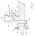
- Figure 2 is a side elevation of the apparatus 50 of the invention, showing a shirred casing portion 30 installed over the stuffing horn 14, but pulled back to reveal the horn ring 15 and stuffing horn.
- the casing material is tubular in shape and is initially stored on a supply reel (not shown).
- brake ring assembly 36 Also shown is brake ring assembly 36, index wheel 16, trailing endclip installers 23 and 25, leading endclip installers 24 and 26, and cutter 27.
- Index wheel 16 is partially broken away to reveal optical sensor 11.
- Figure 3 is a partial cross-sectional view taken generally along line A'-A' of Figure 2.
- Index wheel 16 is shown supported by vertical support members 21 and 22, which, in turn, are supported by horizontal member 39 which, in turn, is mounted to piston 38 of pneumatic cylinder 40.
- Cylinder 40 is mounted to top horizontal support member 19 which is mounted to the filling machine by vertical support member 18.
- the index wheel is brought into contact with horn ring 15 by pneumatic cylinder 40, which is driven by a 172 kPa (25 psi) source and is pressure regulated to ensure that the wheel turns in a 1:1 ratio as the casing moves over the horn ring.
- the necessary pressure is determined experimentally and may vary depending upon the diameter and coefficient of friction of the casing and horn ring. Obviously, too much pressure would tend to brake the casing, and too little pressure would result in the casing slipping with respect to the index wheel.
- index wheel 16 is approximately 30 cm (12 inches) in diameter and is divided into eighteen (18) pie sections (other diameter wheels and different pie section configurations may be used as well.) Index wheel 16 is coupled to proximity sensing device 12 which generates 24 VDC (volts direct current) pulses as the wheel rotates. The PLC uses these pulses to determine the rotational speed of the wheel and the rate of linear motion of the casing.
- VDC volts direct current
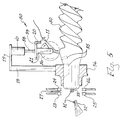
- Figure 4 is a view similar to that of Figure 2 except showing the casing portion 30 pulled over the horn ring 15 (shown in Figures 2 and 3) to align eye-mark bar 31 with sensing means 11, and also showing the leading end of the casing in position for clipping under clipping means 24 and 26.
- Clipping means 24 and 26 apply an endclip to the leading end of a casing portion
- clipping means 23 and 25 apply an endclip to the trailing end of a casing portion.
- Cutting means 27 is located between the leading and trailing clipping means and functions to cut the casing material at the eye-mark bar between filled casing portions, in response to a command from the PLC.
- the fixed length between eye-mark bars is manually programmed into the PLC.
- the starting point is then read into the PLC, which is the point where the first eye-mark bar is aligned with optical sensor 11 as shown in Figure 4.
- Optical sensor 11 is always active, but the PLC is programmed to ignore the printed label material between eye-mark bars.
- the PLC is programmed to look for the eye-mark bars within a certain distance window.
- this window may be 10 cm (four inches) in length, and may be programmed to begin at a point equal to the length of an individual casing portion minus 5 cm (two inches) [assuming a total individual casing portion length of 76 cm (thirty inches)].
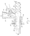
- Figure 6 is a view similar to that of Figure 2 except with trailing eye-mark bar 34 aligned under the sensing means, as the casing portion continues to be filled with food emulsion, and continues to move from right to left.
- This figure clearly shows how label 35 is being centered between the leading clipped end of the casing portion and the trailing end defined by eye-mark bar 34.
- the PLC processes a command to the clipper and cutter to precisely clip the casing and to cut it at eye-mark bar 34.
- Figure 7 is a view similar to that of Figure 2 except showing the trailing end of the filled casing portion being clipped and cut at eye-mark bar 34, and also illustrating the leading end of a subsequent casing portion being clipped as the process begins anew.
- Label 35 is centered perfectly between the ends of the stuffed casing portion.
- the appendix contains a program listing of software used to run the apparatus and is considered to be part of the description.
Landscapes
- Life Sciences & Earth Sciences (AREA)
- Engineering & Computer Science (AREA)
- Wood Science & Technology (AREA)
- Zoology (AREA)
- Food Science & Technology (AREA)
- Containers And Plastic Fillers For Packaging (AREA)
- Making Paper Articles (AREA)
Applications Claiming Priority (2)
| Application Number | Priority Date | Filing Date | Title |
|---|---|---|---|
| US261659 | 1988-10-24 | ||
| US08/261,659 US5573454A (en) | 1994-06-17 | 1994-06-17 | Method and apparatus for aligning labels on shirred food casings |
Publications (3)
| Publication Number | Publication Date |
|---|---|
| EP0692193A2 EP0692193A2 (en) | 1996-01-17 |
| EP0692193A3 EP0692193A3 (en) | 1997-07-02 |
| EP0692193B1 true EP0692193B1 (en) | 2000-08-23 |
Family
ID=22994273
Family Applications (1)
| Application Number | Title | Priority Date | Filing Date |
|---|---|---|---|
| EP94114784A Expired - Lifetime EP0692193B1 (en) | 1994-06-17 | 1994-09-20 | Method and apparatus for aligning labels on shirred food casings |
Country Status (7)
| Country | Link |
|---|---|
| US (1) | US5573454A (da) |
| EP (1) | EP0692193B1 (da) |
| CA (1) | CA2131978C (da) |
| DE (1) | DE69425652T2 (da) |
| DK (1) | DK0692193T3 (da) |
| ES (1) | ES2152962T3 (da) |
| FI (1) | FI104614B (da) |
Families Citing this family (21)
| Publication number | Priority date | Publication date | Assignee | Title |
|---|---|---|---|---|
| US5879385A (en) * | 1993-06-11 | 1999-03-09 | Hillway Surgical Limited | Surgical implant |
| DE19519394C2 (de) * | 1995-05-26 | 1997-03-13 | Poly Clip System Gmbh & Co Kg | Verfahren zum Herstellen von Würsten |
| US5600308A (en) * | 1995-06-23 | 1997-02-04 | Devro-Teepak, Inc. | Method for detecting a position on a product |
| US6558241B2 (en) * | 2000-10-05 | 2003-05-06 | Townsend Engineering Company | Method and apparatus for controlling the operation of a sausage making machine |
| DE50111970D1 (de) * | 2001-11-19 | 2007-03-15 | Handtmann Albert Maschf | Längeneinheit mit Clipmodul |
| US6719621B2 (en) * | 2002-05-31 | 2004-04-13 | Townsend Engineering Company | Method and means for stuffing natural casings with sausage emulsion |
| DE50206066D1 (de) * | 2002-11-22 | 2006-05-11 | Handtmann Albert Maschf | Vorrichtung mit Vakuumfüller und Clipmodul |
| US7704129B2 (en) * | 2005-07-12 | 2010-04-27 | Tipper Tie, Inc. | Ruckers capable of rucking fixed diameter coverings and associated devices, methods, systems and computer program products |
| US7775859B2 (en) * | 2005-07-25 | 2010-08-17 | Tipper Tie, Inc. | Low profile ruckers capable of rucking fixed diameter coverings and associated devices, methods, systems and computer program products |
| DE102005044879B3 (de) * | 2005-09-20 | 2006-09-28 | Poly-Clip System Gmbh & Co. Kg | Rückhaltevorrichtung mit Kurbelgetriebe |
| DE102007011422B3 (de) * | 2007-03-08 | 2008-08-21 | Poly-Clip System Gmbh & Co. Kg | Automatische Spreizverstellung |
| DE102007012777B4 (de) * | 2007-03-16 | 2010-06-24 | Poly-Clip System Gmbh & Co Kg | Verfahren und Vorrichtung zum gesteuerten Verschließen wenigstens eines Clips um einen füllgutfreien Zopfabschnitt zwischen zwei mit einer Hülle umschlossenen Füllgutabschnitten |
| DE102007021047A1 (de) * | 2007-05-04 | 2008-11-06 | Poly-Clip System Gmbh & Co. Kg | Verfahren und Vorrichtung zum gesteuerten Verschließen wenigstens eines Clips um einen füllgutfreien Zopfabschnitt einer schlauchförmigen Hülle an einem mit der Hülle umschlossenen Füllgutabschnitt |
| US8808066B2 (en) * | 2007-09-25 | 2014-08-19 | Poly-Clip System Corp. | Plastic wire clipper/stuffer |
| EP2489274A1 (en) * | 2011-02-15 | 2012-08-22 | Poly-clip System GmbH & Co. KG | Clipping machine and control method for loosely filled products |
| US8795037B2 (en) * | 2012-08-15 | 2014-08-05 | Precitec Corp. | Double clipper |
| US10011380B2 (en) | 2013-08-26 | 2018-07-03 | Tipper Tie, Inc. | Ruckers, reruckers, deruckers and/or skin brakes with stacked gripper layers and related grippers |
| USD729294S1 (en) | 2013-08-26 | 2015-05-12 | Tipper Tie, Inc. | Gripper for automated ruckers, reruckers, deruckers and/or skin brakes |
| EP3162213B1 (en) * | 2014-06-30 | 2018-08-15 | Mayekawa Mfg. Co., Ltd. | Scapula incision device |
| US9669952B2 (en) | 2014-10-31 | 2017-06-06 | Tipper Tie, Inc. | Systems with wheel saddles that can cooperate with wheels of encoders and related devices and methods |
| US11160283B2 (en) * | 2020-02-28 | 2021-11-02 | Poly-Clip System Gmbh & Co. Kg | Four clip clipping machine |
Family Cites Families (13)
| Publication number | Priority date | Publication date | Assignee | Title |
|---|---|---|---|---|
| NL212967A (da) * | 1955-12-27 | 1900-01-01 | ||
| US3112516A (en) * | 1960-09-19 | 1963-12-03 | Tee Pak Inc | Control for shirring machine |
| DE2025620A1 (de) * | 1970-05-26 | 1971-12-09 | Schnell, Karl, 7065 Winterbach | Wurstfullvomchtung |
| US4044426A (en) * | 1975-10-30 | 1977-08-30 | Union Carbide Corporation | Stuffing apparatus |
| US4017941A (en) * | 1975-10-30 | 1977-04-19 | Union Carbide Corporation | Casing sensing means for stuffing apparatus |
| EP0096378B1 (de) * | 1982-06-02 | 1986-04-30 | Teepak Produktie N.V. | Verfahren und Anordnung zum automatisierten Herstellen von Würsten im Strang |
| US4580316A (en) * | 1984-02-02 | 1986-04-08 | Teepak Produktie, N.V. | Hose material to be used as sausage casing, in particular in the automated manufacture of sausage strings on a sausage stuffing machine |
| DE3608983A1 (de) * | 1986-03-18 | 1987-10-01 | Niedecker Herbert | Verfahren zum verschliessen einer gefuellten verpackungshuelle |
| US4991260A (en) * | 1989-01-17 | 1991-02-12 | Viskase Corporation | Stuffing method and apparatus |
| DE9001076U1 (de) * | 1990-01-31 | 1990-08-30 | Albert Handtmann Maschinenfabrik GmbH & Co KG, 7950 Biberach | Füllmaschine zum Herstellen von Würsten durch Abteilen eines Wurststranges |
| US5372537A (en) * | 1992-06-25 | 1994-12-13 | Stiles; Michael F. | Apparatus and method for arranging elongated food casings on a support |
| DE9400771U1 (de) * | 1994-01-18 | 1994-03-03 | Poly-Clip System GmbH, 60489 Frankfurt | Vorrichtung zum Verschließen von gefüllten Verpackungshüllen |
| US5405288A (en) * | 1994-04-26 | 1995-04-11 | Teepak, Inc. | Devices for gathering and clipping tubular food casings and food stuffing machines equipped therewith |
-
1994
- 1994-06-17 US US08/261,659 patent/US5573454A/en not_active Expired - Fee Related
- 1994-09-13 CA CA002131978A patent/CA2131978C/en not_active Expired - Fee Related
- 1994-09-20 ES ES94114784T patent/ES2152962T3/es not_active Expired - Lifetime
- 1994-09-20 DE DE69425652T patent/DE69425652T2/de not_active Expired - Fee Related
- 1994-09-20 EP EP94114784A patent/EP0692193B1/en not_active Expired - Lifetime
- 1994-09-20 DK DK94114784T patent/DK0692193T3/da active
- 1994-09-27 FI FI944470A patent/FI104614B/fi active
Also Published As
| Publication number | Publication date |
|---|---|
| DE69425652D1 (de) | 2000-09-28 |
| FI944470A0 (fi) | 1994-09-27 |
| ES2152962T3 (es) | 2001-02-16 |
| FI104614B (fi) | 2000-03-15 |
| DE69425652T2 (de) | 2001-05-03 |
| US5573454A (en) | 1996-11-12 |
| DK0692193T3 (da) | 2000-12-27 |
| EP0692193A2 (en) | 1996-01-17 |
| CA2131978A1 (en) | 1995-12-18 |
| CA2131978C (en) | 2002-11-12 |
| EP0692193A3 (en) | 1997-07-02 |
| FI944470A7 (fi) | 1995-12-18 |
Similar Documents
| Publication | Publication Date | Title |
|---|---|---|
| EP0692193B1 (en) | Method and apparatus for aligning labels on shirred food casings | |
| US5743792A (en) | Process of producing sausages | |
| FI74589C (fi) | Foerfarande och anordning foer automatisk framstaellning av korvstaenger. | |
| US3383222A (en) | Shirred sausage casing having compressed plug end closure | |
| EP2460412B1 (en) | Clipping machine and method for controlling said clipping machine | |
| AU2003218387B2 (en) | Method and means for stuffing natural casings with sausage emulsion | |
| US3865954A (en) | Closure for shirred casing sticks | |
| US6920738B2 (en) | Push/pull clip feed configuration for selectively delivering or withdrawing a clip to allow output of one clip alone or two clips concurrently and associated devices, methods, systems and computer program products | |
| NZ231280A (en) | Dividing intestine used for sausages into lengths having certain diameters and feeding same onto individual supports | |
| EP1553842B1 (en) | Method and means for stuffing natural casings with a food emulsion | |
| EP0156938B1 (en) | Article for controlling casing depletion | |
| US4649961A (en) | High coherency shirred casings | |
| EP2428119B1 (en) | Whey suction device | |
| EP0760210B1 (en) | Zero time clipper | |
| GB2100571A (en) | Tension sleeve supported casing article | |
| US4756057A (en) | Method of making high coherency shirred casing | |
| US4748720A (en) | Hornless stuffing method and apparatus | |
| EP0687415A2 (en) | Eye-mark bar printed casing for position control by an automatic sizing machine | |
| EP3732979A1 (en) | Clipping machine with improved discharge device | |
| MXPA96002289A (en) | Engrapadora in time c | |
| NZ215415A (en) | Apparatus for detecting depletion of casing from shirred casing strand |
Legal Events
| Date | Code | Title | Description |
|---|---|---|---|
| PUAI | Public reference made under article 153(3) epc to a published international application that has entered the european phase |
Free format text: ORIGINAL CODE: 0009012 |
|
| AK | Designated contracting states |
Kind code of ref document: A2 Designated state(s): BE DE DK ES FR GB IT NL |
|
| PUAL | Search report despatched |
Free format text: ORIGINAL CODE: 0009013 |
|
| AK | Designated contracting states |
Kind code of ref document: A3 Designated state(s): BE DE DK ES FR GB IT NL |
|
| 17P | Request for examination filed |
Effective date: 19971201 |
|
| GRAG | Despatch of communication of intention to grant |
Free format text: ORIGINAL CODE: EPIDOS AGRA |
|
| 17Q | First examination report despatched |
Effective date: 19990823 |
|
| GRAG | Despatch of communication of intention to grant |
Free format text: ORIGINAL CODE: EPIDOS AGRA |
|
| GRAH | Despatch of communication of intention to grant a patent |
Free format text: ORIGINAL CODE: EPIDOS IGRA |
|
| RAP1 | Party data changed (applicant data changed or rights of an application transferred) |
Owner name: TEEPAK INVESTMENTS, INC. |
|
| GRAH | Despatch of communication of intention to grant a patent |
Free format text: ORIGINAL CODE: EPIDOS IGRA |
|
| GRAA | (expected) grant |
Free format text: ORIGINAL CODE: 0009210 |
|
| AK | Designated contracting states |
Kind code of ref document: B1 Designated state(s): BE DE DK ES FR GB IT NL |
|
| PG25 | Lapsed in a contracting state [announced via postgrant information from national office to epo] |
Ref country code: BE Free format text: LAPSE BECAUSE OF FAILURE TO SUBMIT A TRANSLATION OF THE DESCRIPTION OR TO PAY THE FEE WITHIN THE PRESCRIBED TIME-LIMIT Effective date: 20000823 |
|
| REF | Corresponds to: |
Ref document number: 69425652 Country of ref document: DE Date of ref document: 20000928 |
|
| ITF | It: translation for a ep patent filed | ||
| ET | Fr: translation filed | ||
| REG | Reference to a national code |
Ref country code: DK Ref legal event code: T3 |
|
| REG | Reference to a national code |
Ref country code: ES Ref legal event code: FG2A Ref document number: 2152962 Country of ref document: ES Kind code of ref document: T3 |
|
| PLBE | No opposition filed within time limit |
Free format text: ORIGINAL CODE: 0009261 |
|
| STAA | Information on the status of an ep patent application or granted ep patent |
Free format text: STATUS: NO OPPOSITION FILED WITHIN TIME LIMIT |
|
| 26N | No opposition filed | ||
| PGFP | Annual fee paid to national office [announced via postgrant information from national office to epo] |
Ref country code: FR Payment date: 20010911 Year of fee payment: 8 |
|
| PGFP | Annual fee paid to national office [announced via postgrant information from national office to epo] |
Ref country code: DK Payment date: 20010913 Year of fee payment: 8 |
|
| PGFP | Annual fee paid to national office [announced via postgrant information from national office to epo] |
Ref country code: GB Payment date: 20010919 Year of fee payment: 8 |
|
| PGFP | Annual fee paid to national office [announced via postgrant information from national office to epo] |
Ref country code: ES Payment date: 20010920 Year of fee payment: 8 |
|
| PGFP | Annual fee paid to national office [announced via postgrant information from national office to epo] |
Ref country code: NL Payment date: 20010927 Year of fee payment: 8 |
|
| PGFP | Annual fee paid to national office [announced via postgrant information from national office to epo] |
Ref country code: DE Payment date: 20011009 Year of fee payment: 8 |
|
| REG | Reference to a national code |
Ref country code: GB Ref legal event code: IF02 |
|
| PGFP | Annual fee paid to national office [announced via postgrant information from national office to epo] |
Ref country code: BE Payment date: 20020118 Year of fee payment: 8 |
|
| PG25 | Lapsed in a contracting state [announced via postgrant information from national office to epo] |
Ref country code: GB Free format text: LAPSE BECAUSE OF NON-PAYMENT OF DUE FEES Effective date: 20020920 |
|
| PG25 | Lapsed in a contracting state [announced via postgrant information from national office to epo] |
Ref country code: ES Free format text: LAPSE BECAUSE OF NON-PAYMENT OF DUE FEES Effective date: 20020921 |
|
| PG25 | Lapsed in a contracting state [announced via postgrant information from national office to epo] |
Ref country code: DK Free format text: LAPSE BECAUSE OF NON-PAYMENT OF DUE FEES Effective date: 20020930 |
|
| BERE | Be: lapsed |
Owner name: *TEEPAK INVESTMENTS INC. Effective date: 20020930 |
|
| PG25 | Lapsed in a contracting state [announced via postgrant information from national office to epo] |
Ref country code: NL Free format text: LAPSE BECAUSE OF NON-PAYMENT OF DUE FEES Effective date: 20030401 Ref country code: DE Free format text: LAPSE BECAUSE OF NON-PAYMENT OF DUE FEES Effective date: 20030401 |
|
| REG | Reference to a national code |
Ref country code: DK Ref legal event code: EBP |
|
| GBPC | Gb: european patent ceased through non-payment of renewal fee |
Effective date: 20020920 |
|
| PG25 | Lapsed in a contracting state [announced via postgrant information from national office to epo] |
Ref country code: FR Free format text: LAPSE BECAUSE OF NON-PAYMENT OF DUE FEES Effective date: 20030603 |
|
| REG | Reference to a national code |
Ref country code: FR Ref legal event code: ST |
|
| REG | Reference to a national code |
Ref country code: ES Ref legal event code: FD2A Effective date: 20031011 |
|
| PG25 | Lapsed in a contracting state [announced via postgrant information from national office to epo] |
Ref country code: IT Free format text: LAPSE BECAUSE OF NON-PAYMENT OF DUE FEES Effective date: 20050920 |