EP0691602A1 - Biegsame Tastaturstruktur für ein Rechner des Typs Notebook - Google Patents
Biegsame Tastaturstruktur für ein Rechner des Typs Notebook Download PDFInfo
- Publication number
- EP0691602A1 EP0691602A1 EP95304274A EP95304274A EP0691602A1 EP 0691602 A1 EP0691602 A1 EP 0691602A1 EP 95304274 A EP95304274 A EP 95304274A EP 95304274 A EP95304274 A EP 95304274A EP 0691602 A1 EP0691602 A1 EP 0691602A1
- Authority
- EP
- European Patent Office
- Prior art keywords
- plate member
- upper side
- side portion
- keyboard structure
- support plate
- Prior art date
- Legal status (The legal status is an assumption and is not a legal conclusion. Google has not performed a legal analysis and makes no representation as to the accuracy of the status listed.)
- Withdrawn
Links
Images
Classifications
-
- G—PHYSICS
- G06—COMPUTING OR CALCULATING; COUNTING
- G06F—ELECTRIC DIGITAL DATA PROCESSING
- G06F1/00—Details not covered by groups G06F3/00 - G06F13/00 and G06F21/00
- G06F1/16—Constructional details or arrangements
- G06F1/1613—Constructional details or arrangements for portable computers
- G06F1/1615—Constructional details or arrangements for portable computers with several enclosures having relative motions, each enclosure supporting at least one I/O or computing function
- G06F1/1616—Constructional details or arrangements for portable computers with several enclosures having relative motions, each enclosure supporting at least one I/O or computing function with folding flat displays, e.g. laptop computers or notebooks having a clamshell configuration, with body parts pivoting to an open position around an axis parallel to the plane they define in closed position
-
- G—PHYSICS
- G06—COMPUTING OR CALCULATING; COUNTING
- G06F—ELECTRIC DIGITAL DATA PROCESSING
- G06F1/00—Details not covered by groups G06F3/00 - G06F13/00 and G06F21/00
- G06F1/16—Constructional details or arrangements
- G06F1/1613—Constructional details or arrangements for portable computers
- G06F1/1633—Constructional details or arrangements of portable computers not specific to the type of enclosures covered by groups G06F1/1615 - G06F1/1626
- G06F1/1662—Details related to the integrated keyboard
- G06F1/1664—Arrangements for ergonomically adjusting the disposition of keys of the integrated keyboard
-
- H—ELECTRICITY
- H01—ELECTRIC ELEMENTS
- H01H—ELECTRIC SWITCHES; RELAYS; SELECTORS; EMERGENCY PROTECTIVE DEVICES
- H01H13/00—Switches having rectilinearly-movable operating part or parts adapted for pushing or pulling in one direction only, e.g. push-button switch
- H01H13/70—Switches having rectilinearly-movable operating part or parts adapted for pushing or pulling in one direction only, e.g. push-button switch having a plurality of operating members associated with different sets of contacts, e.g. keyboard
-
- H—ELECTRICITY
- H01—ELECTRIC ELEMENTS
- H01H—ELECTRIC SWITCHES; RELAYS; SELECTORS; EMERGENCY PROTECTIVE DEVICES
- H01H2217/00—Facilitation of operation; Human engineering
- H01H2217/028—Facilitation of operation; Human engineering on planes with different or alterable inclination, e.g. convex plane
- H01H2217/03—Concave plane
-
- H—ELECTRICITY
- H01—ELECTRIC ELEMENTS
- H01H—ELECTRIC SWITCHES; RELAYS; SELECTORS; EMERGENCY PROTECTIVE DEVICES
- H01H2223/00—Casings
- H01H2223/046—Casings convertible
- H01H2223/052—Casings convertible reductible in size, e.g. for transportation
Definitions
- the present invention relates generally to computer apparatus and, in a preferred embodiment thereof, more particularly relates to keyboard structures for portable computers such as notebook computers.
- This design challenge arises from two conflicting design goals - the desire to even further reduce the size of the keyboard structure, and the desirability of having the notebook computer emulate as closely as possible the size and typing "feel" of a desktop computer keyboard.
- a feature which has previously been built into a desktop computer keyboard is a "sculpted" configuration in which the keyboard is upwardly and rearwardly tilted and given an upwardly concave configuration to improve typing comfort. This has been done on desktop keyboards by bending the components onto a rigid curved base structure with the keyboard remaining permanently flexed.
- a portable computer representatively a notebook computer
- the computer includes a base housing having a top side, a bottom side, and opposed front and rear sides.
- a lid housing is secured to the rear side of the base housing for pivotal movement relative thereto between a closed position in which the lid housing extends across and covers the base housing top side, and an open position in which the lid housing uncovers and exposes the base housing top side.
- the flexible keyboard structure extends across the top side of the base housing and includes a flexible upper side portion upon which a series of key members are operatively carried, the upper side portion of the keyboard structure being resiliently bendable between an essentially flat storage and transport orientation in which the upper side portion is essentially parallel to the top side of the base housing, and a use orientation in which the upper side portion of the keyboard structure is resiliently bent to an upwardly concave curvature and preferably slopes in a rearward and upward direction relative to the base housing.
- Linkage means interconnect the lid housing and the flexible upper side portion of the keyboard structure.
- the linkage means are operative to (1) position the upper side portion of the keyboard in its storage and transport orientation in response to movement of the lid housing to its closed position, and (2) position the upper side portion of the keyboard in its use orientation in response to movement of the lid housing to its open position.
- the keyboard structure in its flat storage and transport orientation is not appreciably thicker than portable computer keyboard structures of conventional constructions.
- the keyboard structure advantageously emulates the comfortable shape and typing feel of a sculpted desktop computer keyboard.
- the present invention provides a portable computer, illustratively a notebook computer 10, having incorporated therein a specially designed flexing keyboard structure 12 embodying principles of the present invention.
- Computer 10 includes a hollow rectangular base housing 14 having an open top side 16; a bottom horizontal side wall 20; front and rear vertical end walls 22,24; and a pair of opposite vertical side walls 26,28.
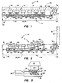
- Lid housing 30 may upwardly pivoted to place the computer 10 in an open use orientation (FIG. 2) in which the top side 16 of the base housing 14 is exposed and the display screen 32 forwardly faces the user of the computer, or downwardly pivoted to place the computer 10 in a closed storage and transport orientation (FIG. 1) in which the lid housing extends across and covers the top side of the base housing 14.
- Suitable latch means (not shown) are provided to releasably retain the lid housing 30 in its FIG. 1 closed orientation.
- the flexing keyboard structure 12 of the present invention extends across an upper portion of the interior of the base housing 14, adjacent its open upper side 16, and includes a horizontally oriented rigid support plate 36 anchored within the interior of the base housing 14 and forming the base of the flexing keyboard structure 12.
- a horizontally oriented rigid support plate 36 anchored within the interior of the base housing 14 and forming the base of the flexing keyboard structure 12.
- three spaced apart stop projections 38,40,42 are formed on the top side of the support plate 36 adjacent each of its opposite ends 44,46.
- a rigid position adjusting plate member 48 is suitably secured to the top side of the support plate 36 for sliding front-to-rear movement relative thereto.
- a central rear portion of the plate member 48 has a slot 50 formed therein, and a pair of rectangular openings 52 are formed in the plate member, forwardly of the slot 50, to define thereon three arm portions 54 extending between and joining front and rear sections of the plate 48.
- upwardly projecting wedge members 56 extend across the top sides of the position adjusting plate arms 56 at their front ends.
- the flexing keyboard structure 12 also includes a generally conventional multi-layer membrane type flexible signal pad structure 58 which overlies the position adjusting plate 48 and has a central portion 60 anchored to the rigid support plate 36.
- the bottom side of the flexible signal pad structure 58 is defined by a resiliently bendable metal plate member 62. Disposed atop the metal plate member 62 are the usual series of plastic sheets upon which various keystroke detection and output circuitry is operatively disposed.
- the top or dome sheet layer of the pad structure 58 has a spaced series of resilient elastomeric key return domes 64 which underlie a series of key cap members 66 operatively secured to the top side of the pad structure 58.
- an upper side portion of the overall keyboard structure 12, namely the signal pad structure 58 that operatively carries the key cap members 66, is selectively and resiliently bendable between an essentially flat storage and transport orientation (FIG. 1), in which the signal pad structure 58 is generally parallel to the bottom wall 20 of the base housing 14, and a use orientation (FIG. 2) in which the top side of the keyboard structure is tilted upwardly and rearwardly and has an upwardly concave curvature giving it the "sculpted" use configuration of a desktop computer keyboard.
- the flexing keyboard structure 12 is automatically moved to its FIG. 1 flat storage and transport orientation in response to closing the lid housing 30, and is automatically moved to its FIG. 2 use orientation (see FIG. 3 also) in response to opening the lid housing 30. Accordingly, in its flat storage and transport orientation the keyboard structure 12 has a vertical thickness comparable to that of a conventional notebook computer keyboard, and in its use orientation the flexing keyboard structure 12 is provided with an upwardly curved, vertically thicker configuration that emulates the shape and typing feel of a sculpted desktop keyboard.
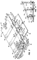
- the flexible multilayer signal pad structure 58 is associated with the lid housing 30 for movement between the FIG. 1 and 2 positions of the pad structure 58 in response to opening and closing of the lid housing 30 by linkage means that include the movable position adjusting plate 48, three rectangular pivot plate members 68,70 and 72, and a pair of intermeshed circular gear members 74,76 rotatably supported within a rear portion of the base housing 14.
- Gear 74 is linked to the lid housing 30 by a rack member 78 secured to the lid housing adjacent its hinge joint 74 and intermeshed with a top side portion of the gear 74.
- Gear 76 is drivingly linked to the position adjusting plate 48 by a lever 80 fixedly secured to the gear 76, projecting radially outwardly therefrom, and extending downwardly through the rear side slot 50 in the position adjusting plate 48.
- a rear side portion of the flexible signal pad structure 58 is linked to the position adjusting plate 48 by the three pivot plate members 68,70 and 72, with plate member 68 being positioned forwardly of plate member 70 which, in turn, is positioned forwardly of plate member 72.
- bottom side edge portions of the plate members 68,70,72 have three notches 82 formed therein, and mounting pins 84 extend horizontally across the notches 82.
- the pins 84 pivotally secure lower side edge portions of the pivot plate members 68,70,72 to the position adjustment plate 48 and are received in sets of three upturned eye members 86,88,90 formed on each of the arm portions 54 of the plate 48.
- Upper corner portions 92 of the pivot plate members 68,70,72 are transversely enlarged and are pivotally secured, as best illustrated in FIG. 3, to the opposite ends 94,96 of the flexible signal pad structure 58.
- the width of the front pivot plate member 68 (between its pivot points) is less than the width of the intermediate pivot plate member 70 which, in turn, is less than the width of the rear pivot plate member 72.
- the vertical heights and horizontal widths of the eyes 86,88,90 are varied as best indicated in FIG. 4. Specifically, the width of the eye 86 is greater than the width of eye 88 which, in turn, is greater than the width of eye 90. The height of eye 86 is less than the height of eye 88 which, in turn, is less than the height of eye 90.
- the signal pad structure 58 is essentially parallel to the bottom base housing wall 20, the wedge members 56 are disposed forwardly of the front end of the signal pad structure 58, and the signal pad structure is releasably secured in its flat orientation by a spaced plurality of rearwardly opening hook members 98 (see FIG. 5) disposed on a front underside portion of the signal pad structure 58 and releasably interlocked with a spaced plurality of forwardly opening hook members 100 disposed on a front upper side portion of the position adjusting plate 48.
- the gear 74 is driven in a clockwise direction, thereby rotating the gear 66 and its associated lever 80 in a counterclockwise direction.
- the lever 80 is driven in a counterclockwise direction it rearwardly drives the position adjusting plate 48 relative to the rigid support plate 36 and the flexible signal pad structure.
- This rearward driven movement of the position adjusting plate 48 rearwardly drives the wedge members 56 between front portions of the support plate 36 and the flexible signal pad structure 58, thereby upwardly bending a front portion of the signal pad structure as indicated.
- the rearward movement of the position adjusting plate 48 disengages the hook members 98 from the hook members 100, thereby permitting the upward bending of a front portion of the signal pad structure 58.
- the rearward driven movement of the position adjusting plate 48 also forcibly translates the bottom side edges of the pivot plate members 68,70,72 in a rearward direction, until they are brought into engagement with the stop projections 38,40 and 42 (see FIG. 3), and at the same time forcibly pivots the plate members 68,70,72 in counterclockwise directions about their bottom side edges to their indicated upright positions in which the upright plate members 68,70,72 upwardly bend a rear portion of the flexible signal pad structure.
- the interaction of the wedge member 56 and the pivot plate members 68,70,72 with the flexible signal pad structure 58 in response to the opening of the lid housing 30 holds the signal pad structure 58 in a rearwardly and upwardly sloped use orientation in which an upper side portion of the overall keyboard structure assumes an upwardly concave curvature that emulates the sculpted configuration of a similarly sloped and curved desktop computer keyboard.
- the gear 74 is rotated in a counterclockwise direction, and the gear 76 and its associated lever 80 are driven in clockwise directions.
- the clockwise movement of the lever 80 forwardly drives the position plate 48 relative to the support plate 36 and the signal pad structure 58, thereby removing the wedge members 56 from between the signal pad structure 58 and the support plate 36, collapsing the pivot plate members 68,70,72 to their FIG. 1 orientations, and returning the signal pad structure 58 to its FIG. 1 flat storage and transport orientation.
- the hook members 98 are again engaged with their associated hook members 100 to hold the signal pad structure in its flat storage and transport orientation.
Landscapes
- Engineering & Computer Science (AREA)
- Computer Hardware Design (AREA)
- Theoretical Computer Science (AREA)
- Physics & Mathematics (AREA)
- Human Computer Interaction (AREA)
- General Engineering & Computer Science (AREA)
- General Physics & Mathematics (AREA)
- Mathematical Physics (AREA)
- Input From Keyboards Or The Like (AREA)
Applications Claiming Priority (2)
| Application Number | Priority Date | Filing Date | Title |
|---|---|---|---|
| US268622 | 1994-06-30 | ||
| US08/268,622 US5490037A (en) | 1994-06-30 | 1994-06-30 | Flexing keyboard structure for a notebook computer |
Publications (1)
| Publication Number | Publication Date |
|---|---|
| EP0691602A1 true EP0691602A1 (de) | 1996-01-10 |
Family
ID=23023790
Family Applications (1)
| Application Number | Title | Priority Date | Filing Date |
|---|---|---|---|
| EP95304274A Withdrawn EP0691602A1 (de) | 1994-06-30 | 1995-06-20 | Biegsame Tastaturstruktur für ein Rechner des Typs Notebook |
Country Status (3)
| Country | Link |
|---|---|
| US (1) | US5490037A (de) |
| EP (1) | EP0691602A1 (de) |
| CA (1) | CA2152865C (de) |
Cited By (1)
| Publication number | Priority date | Publication date | Assignee | Title |
|---|---|---|---|---|
| GB2327209A (en) * | 1997-06-30 | 1999-01-20 | Daewoo Telecom Ltd | Notebook computer with keyboard tilting on opening of computer cover |
Families Citing this family (33)
| Publication number | Priority date | Publication date | Assignee | Title |
|---|---|---|---|---|
| US5615393A (en) * | 1993-03-15 | 1997-03-25 | Elonex I.P. Holdings Ltd. | Computer system having a cordless keyboard and an induction coil in a plug-in electronic card module |
| US5635928A (en) * | 1994-12-23 | 1997-06-03 | Brother Kogyo Kabushiki Kaisha | Data processing device with a keyboard having pop-up keys |
| KR0130878Y1 (ko) * | 1995-07-18 | 1998-12-15 | 김광호 | 휴대용 컴퓨터의 키보드 분할 구조 |
| KR100204158B1 (ko) * | 1995-10-06 | 1999-06-15 | 윤종용 | 분리형 키보드와 이분리형 키보드를 사용한 컴퓨터 |
| JPH09138723A (ja) * | 1995-11-13 | 1997-05-27 | Alps Electric Co Ltd | キーボード装置 |
| US5774384A (en) * | 1995-12-13 | 1998-06-30 | Dell, U.S.A., L.P. | Keyboard with elevatable keys |
| US5764474A (en) * | 1997-03-03 | 1998-06-09 | Compaq Computer Corporation | Portable computer with tilting keyboard that exposes pointing device |
| US6008986A (en) * | 1997-07-30 | 1999-12-28 | International Business Machines Corporation | Laptop computer with slideable keyboard for exposing a heat generating surface for more efficient heat dissipation |
| US6028768A (en) * | 1997-07-30 | 2000-02-22 | International Business Machines Corporation | Mechanism for deploying a keyboard for a portable computer |
| US6038127A (en) * | 1998-02-27 | 2000-03-14 | Comarco Wireless Technologies, Inc. | Keypad assembly using a lead screw assembly for moving a curved member |
| AU3093699A (en) * | 1998-03-16 | 1999-10-11 | Level Iv Technology, Ltd. | Portable computer system with modular interchangeable components |
| JP2002149268A (ja) * | 2000-10-25 | 2002-05-24 | Internatl Business Mach Corp <Ibm> | 携帯情報端末における筐体、その補強方法及びそれを用いた携帯情報端末 |
| US6510048B2 (en) | 2001-01-04 | 2003-01-21 | Apple Computer, Inc. | Keyboard arrangement |
| US6879317B2 (en) | 2001-05-11 | 2005-04-12 | Brian P. Quinn | Collapsible data entry panel |
| US6729783B2 (en) * | 2002-05-20 | 2004-05-04 | Dell Products L.P. | Keyboard deflection control |
| US6762931B2 (en) * | 2002-07-18 | 2004-07-13 | Mitac Technology Corp. | Notebook computer with a keyboard with adjustable angles |
| US9153960B2 (en) | 2004-01-15 | 2015-10-06 | Comarco Wireless Technologies, Inc. | Power supply equipment utilizing interchangeable tips to provide power and a data signal to electronic devices |
| TWI293549B (en) * | 2004-12-24 | 2008-02-11 | Benq Corp | A movement for preventing from generating signal when keypad is touched incautiously |
| US20080024327A1 (en) * | 2006-04-03 | 2008-01-31 | Downs Trevor A | Method and apparatus for ergonomic keyboard |
| USD540335S1 (en) | 2006-04-03 | 2007-04-10 | Downs Trevor A | Wave keypad |
| US8132975B2 (en) * | 2007-04-13 | 2012-03-13 | Hewlett-Packard Development Company, L.P. | Keyboard stiffening system |
| JP5082139B2 (ja) * | 2008-02-28 | 2012-11-28 | Necインフロンティア株式会社 | ブラケットをベースに実装する装置 |
| CN102096444A (zh) * | 2010-12-28 | 2011-06-15 | 富泰华工业(深圳)有限公司 | 具有可升降键盘的电子装置 |
| TWI454885B (zh) * | 2011-09-13 | 2014-10-01 | Wistron Corp | 具有支撐功能之可攜式電子裝置 |
| US9040850B2 (en) | 2011-12-05 | 2015-05-26 | Blackberry Limited | Assembling a keypad to a mobile device |
| US9465413B2 (en) * | 2012-12-10 | 2016-10-11 | Intel Corporation | Keyboard configuration for an electronic device |
| TWI555049B (zh) * | 2012-12-18 | 2016-10-21 | 仁寶電腦工業股份有限公司 | 電子裝置 |
| TWI520168B (zh) * | 2013-06-03 | 2016-02-01 | 緯創資通股份有限公司 | 具有可升降按鍵模組之可攜式電子裝置 |
| US9715286B2 (en) | 2014-01-28 | 2017-07-25 | Solid Art Labs, Inc. | Hand-controllable signal-generating devices and systems |
| US10474201B1 (en) * | 2018-04-23 | 2019-11-12 | Lenovo (Singapore) Pte. Ltd. | Electronic apparatus having an elevation mechanism and method using the same |
| USD1046864S1 (en) | 2022-10-20 | 2024-10-15 | Dunwyvern LLC | Curved keypad |
| TWI857755B (zh) * | 2023-08-18 | 2024-10-01 | 宏碁股份有限公司 | 具快拆鍵盤的筆記型電腦 |
| TW202619442A (zh) * | 2024-10-28 | 2026-05-01 | 緯創資通股份有限公司 | 掀蓋式電子裝置機殼 |
Citations (2)
| Publication number | Priority date | Publication date | Assignee | Title |
|---|---|---|---|---|
| US5278372A (en) * | 1991-11-19 | 1994-01-11 | Brother Kogyo Kabushiki Kaisha | Keyboard having connecting parts with downward open recesses |
| JPH06124154A (ja) * | 1991-07-09 | 1994-05-06 | Nec Corp | 携帯型情報処理装置 |
Family Cites Families (3)
| Publication number | Priority date | Publication date | Assignee | Title |
|---|---|---|---|---|
| SE431955B (sv) * | 1982-07-28 | 1984-03-12 | Ericsson Telefon Ab L M | Tangentbord for terminaler, skrivmaskiner och liknande |
| KR900006479Y1 (ko) * | 1983-04-20 | 1990-07-26 | 부라더 고오교 가부시기가이샤 | 키보드 |
| US5262762A (en) * | 1992-07-02 | 1993-11-16 | Hughes-Avicom International, Inc. | Computer terminal including multi-position attached keyboard |
-
1994
- 1994-06-30 US US08/268,622 patent/US5490037A/en not_active Expired - Lifetime
-
1995
- 1995-06-20 EP EP95304274A patent/EP0691602A1/de not_active Withdrawn
- 1995-06-28 CA CA002152865A patent/CA2152865C/en not_active Expired - Fee Related
Patent Citations (2)
| Publication number | Priority date | Publication date | Assignee | Title |
|---|---|---|---|---|
| JPH06124154A (ja) * | 1991-07-09 | 1994-05-06 | Nec Corp | 携帯型情報処理装置 |
| US5278372A (en) * | 1991-11-19 | 1994-01-11 | Brother Kogyo Kabushiki Kaisha | Keyboard having connecting parts with downward open recesses |
Non-Patent Citations (2)
| Title |
|---|
| "DESIGN FOR ADJUSTABLE KEY HIGHTS ON A COMPUTER KEYBOARD", IBM TECHNICAL DISCLOSURE BULLETIN, vol. 34, no. 8, NEW YORK US, pages 101 - 102, XP000302060 * |
| PATENT ABSTRACTS OF JAPAN vol. 018, no. 417 (P - 1781) 4 August 1994 (1994-08-04) * |
Cited By (1)
| Publication number | Priority date | Publication date | Assignee | Title |
|---|---|---|---|---|
| GB2327209A (en) * | 1997-06-30 | 1999-01-20 | Daewoo Telecom Ltd | Notebook computer with keyboard tilting on opening of computer cover |
Also Published As
| Publication number | Publication date |
|---|---|
| US5490037A (en) | 1996-02-06 |
| CA2152865A1 (en) | 1995-12-31 |
| CA2152865C (en) | 1998-12-29 |
Similar Documents
| Publication | Publication Date | Title |
|---|---|---|
| US5490037A (en) | Flexing keyboard structure for a notebook computer | |
| US5654872A (en) | Collapsible keyboard structure for a notebook computer | |
| US5168427A (en) | Portable computer with tiltable keyboard structure | |
| US5590020A (en) | Collapsible notebook computer keyboard structure with resiliently deflectable key cap skirts | |
| US5602715A (en) | Collapsible keyboard structure for a notebook computer, responsive to opening and closing of the computer's lid via relatively shiftable key support member and shift member | |
| JP4347917B2 (ja) | ポータブル・コンピュータ及びそのキーボード装置 | |
| US5587875A (en) | Collapsible notebook computer keyboard structure with horizontally and downwardly shiftable key return domes | |
| US5621610A (en) | Collapsible computer keyboard structure with associated collapsible pointing stick | |
| US5539615A (en) | Notebook computer keyboard with slot-supported sliding pin tilt mechanism | |
| US6870730B2 (en) | Computer with a pen or touch sensitive display | |
| US5754395A (en) | Ergonomic keyboard for a portable computer which is moveable between two positions | |
| US6903927B2 (en) | Convertible mobile computing device | |
| US5629832A (en) | Electronic device keyboard with pivot bar tilt mechanism | |
| KR100204158B1 (ko) | 분리형 키보드와 이분리형 키보드를 사용한 컴퓨터 | |
| US6125031A (en) | Plastic computer housing/access door apparatus with integrally molded dual function hinge assembly | |
| WO1996003685A1 (en) | Portable computing device having an adjustable hinge | |
| US5729480A (en) | Portable information processing apparatus | |
| US6137676A (en) | Collapsible keyboard mechanism with integrated LCD display | |
| US6034866A (en) | Equipment having openable cover | |
| US5126725A (en) | Foldable electronic apparatus having a display inclinable relative to a keyboard with balance stabilization | |
| US6390699B1 (en) | Keyboard with moveable base plate providing key travel | |
| US5790370A (en) | Collapsible portable computer keyboard structure having springless lid-to-keyboard drive linkage | |
| US6437972B1 (en) | Keyboard with interior stiffening ribs | |
| JP3661504B2 (ja) | 情報処理装置 | |
| US6262881B1 (en) | Compact notebook computer with movable keyboard section |
Legal Events
| Date | Code | Title | Description |
|---|---|---|---|
| PUAI | Public reference made under article 153(3) epc to a published international application that has entered the european phase |
Free format text: ORIGINAL CODE: 0009012 |
|
| AK | Designated contracting states |
Kind code of ref document: A1 Designated state(s): AT BE CH DE DK ES FR GB IE IT LI NL SE |
|
| K1C1 | Correction of patent application (title page) published |
Effective date: 19960110 |
|
| 17P | Request for examination filed |
Effective date: 19960621 |
|
| 17Q | First examination report despatched |
Effective date: 19991006 |
|
| STAA | Information on the status of an ep patent application or granted ep patent |
Free format text: STATUS: THE APPLICATION IS DEEMED TO BE WITHDRAWN |
|
| 18D | Application deemed to be withdrawn |
Effective date: 20000229 |