EP0691000B1 - Optisches system zur zwei- und dreidimensionalen darstellung von information - Google Patents
Optisches system zur zwei- und dreidimensionalen darstellung von information Download PDFInfo
- Publication number
- EP0691000B1 EP0691000B1 EP94912436A EP94912436A EP0691000B1 EP 0691000 B1 EP0691000 B1 EP 0691000B1 EP 94912436 A EP94912436 A EP 94912436A EP 94912436 A EP94912436 A EP 94912436A EP 0691000 B1 EP0691000 B1 EP 0691000B1
- Authority
- EP
- European Patent Office
- Prior art keywords
- prisms
- light
- optical system
- mask
- prism
- Prior art date
- Legal status (The legal status is an assumption and is not a legal conclusion. Google has not performed a legal analysis and makes no representation as to the accuracy of the status listed.)
- Expired - Lifetime
Links
Images



Classifications
-
- G—PHYSICS
- G03—PHOTOGRAPHY; CINEMATOGRAPHY; ANALOGOUS TECHNIQUES USING WAVES OTHER THAN OPTICAL WAVES; ELECTROGRAPHY; HOLOGRAPHY
- G03B—APPARATUS OR ARRANGEMENTS FOR TAKING PHOTOGRAPHS OR FOR PROJECTING OR VIEWING THEM; APPARATUS OR ARRANGEMENTS EMPLOYING ANALOGOUS TECHNIQUES USING WAVES OTHER THAN OPTICAL WAVES; ACCESSORIES THEREFOR
- G03B35/00—Stereoscopic photography
- G03B35/18—Stereoscopic photography by simultaneous viewing
- G03B35/24—Stereoscopic photography by simultaneous viewing using apertured or refractive resolving means on screens or between screen and eye
-
- G—PHYSICS
- G02—OPTICS
- G02B—OPTICAL ELEMENTS, SYSTEMS OR APPARATUS
- G02B30/00—Optical systems or apparatus for producing three-dimensional [3D] effects, e.g. stereoscopic images
- G02B30/20—Optical systems or apparatus for producing three-dimensional [3D] effects, e.g. stereoscopic images by providing first and second parallax images to an observer's left and right eyes
- G02B30/26—Optical systems or apparatus for producing three-dimensional [3D] effects, e.g. stereoscopic images by providing first and second parallax images to an observer's left and right eyes of the autostereoscopic type
- G02B30/27—Optical systems or apparatus for producing three-dimensional [3D] effects, e.g. stereoscopic images by providing first and second parallax images to an observer's left and right eyes of the autostereoscopic type involving lenticular arrays
-
- G—PHYSICS
- G02—OPTICS
- G02B—OPTICAL ELEMENTS, SYSTEMS OR APPARATUS
- G02B30/00—Optical systems or apparatus for producing three-dimensional [3D] effects, e.g. stereoscopic images
- G02B30/20—Optical systems or apparatus for producing three-dimensional [3D] effects, e.g. stereoscopic images by providing first and second parallax images to an observer's left and right eyes
- G02B30/26—Optical systems or apparatus for producing three-dimensional [3D] effects, e.g. stereoscopic images by providing first and second parallax images to an observer's left and right eyes of the autostereoscopic type
- G02B30/33—Optical systems or apparatus for producing three-dimensional [3D] effects, e.g. stereoscopic images by providing first and second parallax images to an observer's left and right eyes of the autostereoscopic type involving directional light or back-light sources
-
- G—PHYSICS
- G02—OPTICS
- G02B—OPTICAL ELEMENTS, SYSTEMS OR APPARATUS
- G02B30/00—Optical systems or apparatus for producing three-dimensional [3D] effects, e.g. stereoscopic images
- G02B30/20—Optical systems or apparatus for producing three-dimensional [3D] effects, e.g. stereoscopic images by providing first and second parallax images to an observer's left and right eyes
- G02B30/34—Stereoscopes providing a stereoscopic pair of separated images corresponding to parallactically displaced views of the same object, e.g. three-dimensional [3D] slide viewers
- G02B30/36—Stereoscopes providing a stereoscopic pair of separated images corresponding to parallactically displaced views of the same object, e.g. three-dimensional [3D] slide viewers using refractive optical elements, e.g. prisms, in the optical path between the images and the observer
-
- H—ELECTRICITY
- H04—ELECTRIC COMMUNICATION TECHNIQUE
- H04N—PICTORIAL COMMUNICATION, e.g. TELEVISION
- H04N13/00—Stereoscopic video systems; Multi-view video systems; Details thereof
- H04N13/30—Image reproducers
- H04N13/302—Image reproducers for viewing without the aid of special glasses, i.e. using autostereoscopic displays
- H04N13/305—Image reproducers for viewing without the aid of special glasses, i.e. using autostereoscopic displays using lenticular lenses, e.g. arrangements of cylindrical lenses
-
- H—ELECTRICITY
- H04—ELECTRIC COMMUNICATION TECHNIQUE
- H04N—PICTORIAL COMMUNICATION, e.g. TELEVISION
- H04N13/00—Stereoscopic video systems; Multi-view video systems; Details thereof
- H04N13/30—Image reproducers
- H04N13/302—Image reproducers for viewing without the aid of special glasses, i.e. using autostereoscopic displays
- H04N13/32—Image reproducers for viewing without the aid of special glasses, i.e. using autostereoscopic displays using arrays of controllable light sources; using moving apertures or moving light sources
-
- H—ELECTRICITY
- H04—ELECTRIC COMMUNICATION TECHNIQUE
- H04N—PICTORIAL COMMUNICATION, e.g. TELEVISION
- H04N13/00—Stereoscopic video systems; Multi-view video systems; Details thereof
- H04N13/30—Image reproducers
- H04N13/366—Image reproducers using viewer tracking
- H04N13/368—Image reproducers using viewer tracking for two or more viewers
-
- H—ELECTRICITY
- H04—ELECTRIC COMMUNICATION TECHNIQUE
- H04N—PICTORIAL COMMUNICATION, e.g. TELEVISION
- H04N13/00—Stereoscopic video systems; Multi-view video systems; Details thereof
- H04N13/30—Image reproducers
- H04N13/366—Image reproducers using viewer tracking
- H04N13/376—Image reproducers using viewer tracking for tracking left-right translational head movements, i.e. lateral movements
-
- H—ELECTRICITY
- H04—ELECTRIC COMMUNICATION TECHNIQUE
- H04N—PICTORIAL COMMUNICATION, e.g. TELEVISION
- H04N13/00—Stereoscopic video systems; Multi-view video systems; Details thereof
- H04N13/30—Image reproducers
- H04N13/398—Synchronisation thereof; Control thereof
-
- H—ELECTRICITY
- H04—ELECTRIC COMMUNICATION TECHNIQUE
- H04N—PICTORIAL COMMUNICATION, e.g. TELEVISION
- H04N13/00—Stereoscopic video systems; Multi-view video systems; Details thereof
- H04N13/20—Image signal generators
- H04N13/204—Image signal generators using stereoscopic image cameras
-
- H—ELECTRICITY
- H04—ELECTRIC COMMUNICATION TECHNIQUE
- H04N—PICTORIAL COMMUNICATION, e.g. TELEVISION
- H04N13/00—Stereoscopic video systems; Multi-view video systems; Details thereof
- H04N13/20—Image signal generators
- H04N13/286—Image signal generators having separate monoscopic and stereoscopic modes
-
- H—ELECTRICITY
- H04—ELECTRIC COMMUNICATION TECHNIQUE
- H04N—PICTORIAL COMMUNICATION, e.g. TELEVISION
- H04N13/00—Stereoscopic video systems; Multi-view video systems; Details thereof
- H04N13/30—Image reproducers
- H04N13/302—Image reproducers for viewing without the aid of special glasses, i.e. using autostereoscopic displays
- H04N13/31—Image reproducers for viewing without the aid of special glasses, i.e. using autostereoscopic displays using parallax barriers
-
- H—ELECTRICITY
- H04—ELECTRIC COMMUNICATION TECHNIQUE
- H04N—PICTORIAL COMMUNICATION, e.g. TELEVISION
- H04N13/00—Stereoscopic video systems; Multi-view video systems; Details thereof
- H04N13/30—Image reproducers
- H04N13/332—Displays for viewing with the aid of special glasses or head-mounted displays [HMD]
- H04N13/337—Displays for viewing with the aid of special glasses or head-mounted displays [HMD] using polarisation multiplexing
-
- H—ELECTRICITY
- H04—ELECTRIC COMMUNICATION TECHNIQUE
- H04N—PICTORIAL COMMUNICATION, e.g. TELEVISION
- H04N13/00—Stereoscopic video systems; Multi-view video systems; Details thereof
- H04N13/30—Image reproducers
- H04N13/332—Displays for viewing with the aid of special glasses or head-mounted displays [HMD]
- H04N13/341—Displays for viewing with the aid of special glasses or head-mounted displays [HMD] using temporal multiplexing
-
- H—ELECTRICITY
- H04—ELECTRIC COMMUNICATION TECHNIQUE
- H04N—PICTORIAL COMMUNICATION, e.g. TELEVISION
- H04N13/00—Stereoscopic video systems; Multi-view video systems; Details thereof
- H04N13/30—Image reproducers
- H04N13/332—Displays for viewing with the aid of special glasses or head-mounted displays [HMD]
- H04N13/344—Displays for viewing with the aid of special glasses or head-mounted displays [HMD] with head-mounted left-right displays
-
- H—ELECTRICITY
- H04—ELECTRIC COMMUNICATION TECHNIQUE
- H04N—PICTORIAL COMMUNICATION, e.g. TELEVISION
- H04N13/00—Stereoscopic video systems; Multi-view video systems; Details thereof
- H04N13/30—Image reproducers
- H04N13/361—Reproducing mixed stereoscopic images; Reproducing mixed monoscopic and stereoscopic images, e.g. a stereoscopic image overlay window on a monoscopic image background
-
- H—ELECTRICITY
- H04—ELECTRIC COMMUNICATION TECHNIQUE
- H04N—PICTORIAL COMMUNICATION, e.g. TELEVISION
- H04N13/00—Stereoscopic video systems; Multi-view video systems; Details thereof
- H04N13/30—Image reproducers
- H04N13/366—Image reproducers using viewer tracking
- H04N13/38—Image reproducers using viewer tracking for tracking vertical translational head movements
Definitions
- the invention relates to an optical system for two- and three-dimensional representation of information using transmission displays for computer and video technology, for head-up displays in the aerospace industry, in advertising and presentation, in medical technology, in the area of virtual reality and in other areas.
- the two stereoscopic fields are usually assigned using additional aids.
- the light representing the two fields is polarized perpendicularly to one another, with the polarization glasses being assigned to the viewer's eyes.
- Another possibility is the sequential presentation of the two fields, which are correctly assigned to the viewer's eyes via synchronously switching shutter glasses.
- the best-known autostereoscopic method uses a lenticular screen, which projects the fields onto the eyes of the viewer pixel by pixel.
- the fixed position of the viewer whose lateral range of motion is limited to one eye distance, is a particular disadvantage.
- the number of pixels per raster lens must be increased.
- the image jumping occurs with the annoying reversal of the depth relationships in the viewed image. Solutions for multiple viewers place even greater demands on the resolution of the displays.
- Such a method for a picture tube is known from WO92 / 03021, it being further proposed here to use prisms instead of the lenticular screen.
- a field lens is not provided.
- Another autostereoscopic method projects linear or point-shaped light sources through the pixels of a transmission display onto the eyes of the viewer.
- the correct assignment is achieved by arranging the light sources so that they are only visible to the right and left eye due to the even and odd columns in the display. Disadvantages are the fixed position of the viewer, the complicated lighting device and the high power for operating the lighting device.
- a switchover for viewing two-dimensional scenes is provided. Processes of this type are known as barrier processes.
- a grid is arranged in front of the display in such a way that only the columns corresponding to the left field are seen on the display through the grid with the left eye. The same applies to the right eye and the corresponding image content.
- the method according to the Australian patent represents a varied barrier method.
- a screen with an otherwise geometrically identical arrangement of prisms is used.
- the prism-free columns of the screen are used as a gate for both the right and the left Field used.
- the rigid assignment of display and viewer is very disadvantageous.
- the two fields or parts of the fields are alternately channeled to the viewer's eyes by a light source from a pair of light sources. This is achieved by means of optical elements with a lens function, the transmission display being located in the area of the aperture diaphragms of the optical elements.
- a disadvantage of this time-sequential method is the required doubling of the image frequency, which, given the switching frequency of the transmission displays, which is still very limited at the present time, places high demands on the implementation if the image is to be seen without flickering.
- the object of the invention is to use a transmission display to offer one or more viewers a clearly visible two-dimensional or three-dimensional autostereographic image, the viewers being able to move laterally and vertically as desired and to see the image without aids.
- the transmission display always contains both fields at the same time. Switching between the fields is not necessary.
- a light source arrangement with at least one punctiform or linear light source, a collimation lens for Parallelization of the light, a transmission display, a prism mask with prisms arranged in a matrix, which have two different prism angles, a field lens as focusing optics, and a phase mask.
- the light is parallelized by the collimation optics and thus projects the left field on a pixel-by-pixel basis onto the associated (left) prisms with one prism angle and the right field onto the associated (right) prisms with the other prism angle.
- the two fields are spatially separated from one another in their directions.
- the focusing optics With the focusing optics, the two parallel bundles are brought together in two points that correspond to the distance between the eyes. The effect of the focusing optics is therefore a single field lens that encompasses the entire image.
- the image composed of the fields can only be seen from these locations.
- the collimation optics produce other directions of parallel bundles, which after passing through the transmission display and the prisms corresponding to the stereoscopic fields are split into other directions and brought together at other points by the focusing optics.
- the stereoscopic fields of the position of the viewer can be tracked.
- several or many viewers can be realized by additional light sources or light source arrangements which deliver the stereoscopic fields at additional locations. They can all move sideways, with the associated light sources being tracked.
- the head movement and the tracking of the light source arrangement can also be used to offer new image contents which correspond to the respective position of the viewer (s). So there is the possibility as in holography, to look behind the displayed object.
- the parallelized light emerging from the collimation optics for one or more viewers can also be formed by several or any number of point or line light sources.
- the lighting can be formed by an array of point-shaped light sources, the light of which is collimated in a direction given by the position of the light sources by means of an array-shaped collimation lens.
- the light output can be reduced and the image can be seen even in bright ambient light.
- phase elements assigned to each pixel with phase strokes randomly distributed across the display act like a matt screen and ensure that the eyes no longer adapt to the brightest point, the light source. Relatively homogeneous image fields can thus be viewed reliably.
- the fields are taken from a two-dimensional information source, e.g. B. every second column for the left or right eye (in the known change of assignment after each scan), and then, distracted and focused on the eyes, to a very visible two-dimensional image with the highest resolution by the transmissions -Display is given, and great brightness reassembled.
- a two-dimensional information source e.g. B. every second column for the left or right eye (in the known change of assignment after each scan)
- distracted and focused on the eyes to a very visible two-dimensional image with the highest resolution by the transmissions -Display is given, and great brightness reassembled.
- the two image contents, each containing two fields, are sequentially activated with the light corresponding to the fields for the viewer. It is also possible to offer more than two TV programs to several viewers at the same time. If all viewers see the same program, no sequential switching is necessary.
- the two fields are offered by activating the light.
- Two or more viewers can only see the images contained in the projections onto the viewer's eyes. This means that the pictures are not accessible to any other person or to any further viewing, and that the pictures do not overlap for two or more viewers. This can be used to advantage. Despite the audience, information can be entered and transmitted via a laptop without third parties being able to see the information. Interesting uses include ATMs, the banking industry and the transmission of confidential information from the business and media sectors.
- the optical system consists of a light source 1, a collimation optics 2, a phase mask 3, a transmission display 4, a prism mask 5 and a focusing optics 6.
- the light of the light source 1 passes through the phase mask 3 and the transmission display 4. Then it is divided into two directions by the prism mask 5 and focused on the eyes 7r and 71 of the viewer by the focusing optics.
- Fig. 2 shows a section consisting of phase mask 3, transmission display 4, prism mask 5 and focusing optics 6 for an observer.
- the prism mask 5 is made up of left and right Prisms formed that direct the light onto the left or right eye of the viewer.
- the prism angles of the right and left prisms are identical to one another over the entire matrix area, but different from one another.
- a prism angle e.g. B. that of the left prisms, zero.
- the light passes these left "prisms" without being deflected and is focused on the left eye of the viewer by the subsequent focusing optics.
- the actually (right) prisms of the prism mask 5 deflect the light entering in parallel. Together with the focusing optics 6, this light is focused on the other (right) eye of the viewer.
- the right and left prisms are assigned 4 right and left pixels in the transmission display, each of which contains the field for the right and left eye.
- the viewer sees a three-dimensional representation. If the fields are stereoscopic fields, the viewer sees a three-dimensional representation. If the fields are taken from a two-dimensional scene, the viewer sees a two-dimensional representation.
- the modulation of the light with randomly distributed optical phase strokes prevents the viewer from adapting to the light source.
- phase and prism mask as well as the focusing optics can be produced as holographic optical elements and / or by means of embossing technology.
- phase mask 3 shows a combination of elements as shown in FIG. 2. 2, the phase mask 3 and the prism mask 5 are advantageously combined to form the combined mask 8 in FIG. 3.
- phase mask 3 shows, according to the invention, a further summary of the elements of phase mask 3, prism mask shown in FIG. 2 5 and focusing optics 6 for the combined mask 9.
- the transmission display 4 and the focusing optics can also be combined with one another in any other order and number.
- the transmission display can be arranged between the combined mask 8 and the focusing optics 6.
- the masks 3, 5, 8, 9 or other masks created by a combination can also be applied directly to the surface of the transmission display.
- a further advantageous embodiment according to the invention consists in the fact that the function of the focusing optics in the mask 6 or in any other combined masks which contain this function is eliminated and is taken over by the collimation optics.
- Fig. 5 shows an arrangement of this type according to the invention.
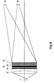
- the viewing direction can be tracked according to the invention. According to FIG. 6 this can be achieved by changing the location of the light source by moving it or by switching on differently positioned light sources 1.
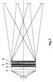
- Fig. 7 shows an optical arrangement with one point or line light source per viewer.
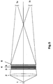
- the optical system enables a customary two-dimensional representation with an enlarged observation angle, as shown in FIG. 8.
- a larger light source 1 is used or generated by switching on further adjacent light sources.
Landscapes
- Physics & Mathematics (AREA)
- Engineering & Computer Science (AREA)
- Multimedia (AREA)
- Signal Processing (AREA)
- General Physics & Mathematics (AREA)
- Optics & Photonics (AREA)
- Testing, Inspecting, Measuring Of Stereoscopic Televisions And Televisions (AREA)
- Stereoscopic And Panoramic Photography (AREA)
- Controls And Circuits For Display Device (AREA)
Description
- Die Erfindung betrifft ein optisches System zur zwei- und dreidimensionalen Darstellung von Information unter Verwendung von Transmissions-Displays für die Computer- und Videotechnik, für Head-Up-Displays in der Luft- und Raumfahrt, in der Werbung und Präsentation, in der Medizintechnik, im Bereich virtuelle Realität und in anderen Bereichen.
- Die zweidimensionale Darstellung von Information unter Verwendung von Transmission-Displays mit matrixförmig angeordneten und elektronisch ansteuerbaren Pixeln ist seit langem bekannt und wird vor allem in der Computer- und Videotechnik und für Spiele und Anzeigen, insbesondere in tragbaren Computern, wie Laptops oder Palmtops, eingesetzt. Ein besonderer Nachteil bei diesen Systemen ist die erhebliche Leistung zum Betreiben der Beleuchtung, die die Batteriebetriebszeit herabsetzt.
- Zur dreidimensionalen Darstellung von Information sind einige Lösungen bekannt.
- Die wichtigste Rolle spielen hierbei stereoskopische Verfahren. Üblicherweise erfolgt die Zuordnung der beiden stereoskopischen Halbbilder durch zusätzliche Hilfsmittel. Dazu wird bei einem bekannten Verfahren das die beiden Halbbilder repräsentierende Licht zueinander senkrecht polarisiert, wobei durch eine Polarisationsbrille die Zuordnung auf die Augen des Betrachters erfolgt.
- Eine andere Möglichkeit besteht in der sequentielle Darbietung der beiden Halbbilder, die über eine synchron schaltende Shutter-Brille den Augen des Betrachters richtig zugeordnet werden.
- Stereoskopische Verfahren haben den großen Nachteil, daß die zusätzlichen Hilfsmittel erforderlich sind. Autostereoskopische Verfahren benötigen diese Hilfsmittel nicht.
- Das bekannteste autostereoskopische Verfahren benutzt ein Linsenraster, das die Halbbilder pixelweise auf die Augen des Betrachters projiziert. Nachteilig ist vor allem die fixierte Position des Betrachters, dessen seitlicher Bewegungsraum auf einen Augenabstand beschränkt ist. Um diesen Spielraum zu vergrößern, muß die Anzahl der Pixel pro Rasterlinse vergrößert werden. Außerdem tritt das Bildspringen mit der lästigen Umkehr der Tiefenverhältnisse im betrachteten Bild auf. Noch größere Forderungen an die Auflösung der Displays stellen Lösungen für mehrere Betrachter. Ein solches Verfahren für eine Bild röhre ist aus WO92/03021 bekannt, wobei hier weiterhin vorgeschlagen wird, anstatt der Linsenraster Prismen zu verwenden. Eine Feldlinse ist jedoch nicht vorgesehen.
- Ein weiteres autostereoskopisches Verfahren (US Patent 5,036,385) projiziert linien- oder punktfömige Lichtquellen durch die Pixel eines Transmissions-Displays auf die Augen des Betrachters. Die richtige Zuordnung entsteht, indem die Lichtquellen so angeordnet sind, daß sie durch die geradzahligen bzw. ungeradzahligen Spalten im Display jeweils nur für das rechte bzw. linke Auge sichbar sind. Nachteilig ist die fixierte Position des Betrachters, die komplizierte Beleuchtungseinrichtung und die große Leistung zum Betreiben der Beleuchtungseinrichtung. Eine Umschaltung für die Betrachtung zweidimensionaler Szenen ist vorgesehen. Verfahren dieser Art sind als Barriereverfahren bekannt. Beim Barriereverfahren ist ein Gitter so vor dem Display angeordnet, daß durch das Gitter hindurch mit dem linken Auge nur die dem linken Halbbild entsprechenden Spalten auf dem Display gesehen werden. Für das rechte Auge und den entsprechendem Bildinhalt gilt Analoges.
- Das Verfahren nach dem australischen Patent (AU-A-13076/92) stellt ein variiertes Barriereverfahren dar. Anstelle des Gitters wird ein Schirm mit sonst geometrisch gleicher Anordnung von Prismen verwendet. Die prismenfreien Spalten des Schirms werden als Tor sowohl für das rechte als auch für das linke Halbbild verwendet. Wie in anderen Barriereverfahren ist die starre Zuordnung von Display und Betrachter sehr nachteilig.
- Beim autostereoskopischen Verfahren nach der DE-OS 40 04 739 werden die beiden Halbbilder oder Teile der Halbbilder durch jeweils eine Lichtquelle eines Lichtquellenpaares abwechselnd auf die Augen des Betrachters kanalisiert. Dies wird durch optische Elemente mit Linsenfunktion erreicht, wobei sich das Transmissions-Display im Bereich der Aperturblenden der optischen Elemente befindet.
- Nachteilig bei diesem zeitsequentiellen Verfahren ist die erforderliche Verdopplung der Bildfrequenz, die bei der zumindest gegenwärtig noch sehr begrenzten Umschaltfrequenz der Transmissions-Displays hohe Anforderungen an die Realisierung stellt, wenn das Bild flackerfrei gesehen werden soll.
- Aufgabe der Erfindung ist es, unter Verwendung eines Transmissions-Display einem oder mehreren Betrachtern ein gut sichtbares zweidimensionales oder dreidimensionales autostereografisches Bild anzubieten, wobei die Betrachter sich beliebig seitlich und in der Höhe bewegen und das Bild ohne Hilfsmittel sehen können.
- Erfindungsgemäß wird die Aufgabe mit den im Anspruch 1 genannten und in den Ausführungsbeispielen näher erläuterten Mitteln gelöst. Dem Oberbegriff des Anspruchs 1 liegt die Druckschrift DE'739 zugrunde.
- Das Transmissions-Display enthält gleichzeitig immer beide Halbbilder. Ein Umschalten zwischen den Halbbildern ist nicht erforderlich.
- Ein bevorzugtes Ausführungsbeispiel des optischen Systems zur zwei- und dreidimensionalen Darstellung von Information enthält folgende Elemente:
- Eine Lichtquellenanordnung mit mindestens einer punkt- oder linienförmigen Lichtquelle, eine Kollimationsoptik zur Parallelisierung des Lichts, ein Transmissions-Display, eine Prismenmaske mit matrixförmig angeordneten Prismen, die zwei voneinander verschiedene Prismenwinkel haben, eine Feldlinse als Fokussieroptik, sowie eine Phasenmaske.
- Das Licht wird durch die Kollimationsoptik parallelisiert und projiziert so pixelweise das linke Halbbild auf die zugehörigen (linken) Prismen mit dem einen Prismenwinkel und das rechte Halbbild auf die zugehörigen (rechten) Prismen mit dem anderen Prismenwinkel. Dadurch werden die beiden Halbbilder in ihren Richtungen räumlich voneinander getrennt. Mit der Fokussieroptik werden die beiden parallelen Bündel in zwei Punkten zusammengeführt, die dem Augenabstand entsprechen. Die Fokussieroptik ist daher in ihrer Wirkung eine einzige, das gesamte Bild umfassende, Feldlinse.
- Das aus den Halbbildern zusammengesetzte Bild kann nur von diesen Orten aus gesehen werden.
- Durch seitliche horizontale Verschiebung der Lichtquelle oder Lichtquellenanordnung erzeugt die Kollimationsoptik andere Richtungen paralleler Bündel, die nach Passieren des Transmissions-Displays und der den stereoskopischen Halbbildern entsprechenden Prismen in andere Richtungen aufgespaltet und durch die Fokussieroptik an anderen Punkten zusammengeführt werden. Auf diese Weise können die stereoskopischen Halbbilder der Position des Betrachters nachgeführt werden. Analog lassen sich durch zusätzliche Lichtquellen oder Lichtquellenanordnungen, die an zusätzlichen Orten die stereoskopischen Halbbilder liefern, mehrere bzw. viele Betrachter realisieren. Sie können sich alle seitlich bewegen, wobei die zugehörigen Lichtquellen nachgeführt werden.
- Für einen oder einige wenige Betrachter können mit der Kopfbewegung und der Nachführung der Lichtquellenanordnung auch neue Bildinhalte angeboten werden, die der jeweiligen Position des oder der Betrachter entsprechen. So besteht die Möglichkeit, wie in der Holografie, auch hinter das dargestellte Objekt zu schauen.
- Das aus der Kollimationsoptik austretende parallelisierte Licht für einen oder mehrere Betrachter kann auch von mehreren oder beliebig vielen punkt- oder linienförmigen Lichtquellen gebildet werden. Beispielsweise kann für einen Betrachter die Beleuchtung durch ein Array von punktförmigen Lichtquellen gebildet werden, deren Licht durch eine arrayförmig gestaltete Kollimationsoptik in eine durch die Lage der Lichtquellen gegebene Richtung kollimiert wird.
- Durch die Bündelung des Lichts kann die Lichtleistung verringert und das Bild auch bei hellem Umgebungslicht gesehen werden.
- Die jedem Pixel zugeordneten Phasenelemente mit zufällig über das Display verteilten Phasenhüben wirken wie eine Mattscheibe und sichern, daß die Augen nicht mehr auf die hellste Stelle, die Lichtquelle, adaptieren. Damit können auch relativ homogene Bildfelder zuverlässig betrachtet werden.
- Insgesamt wird eine hohe Bildqualität erreicht, und zwar sowohl bei der zwei- als auch bei der dreidimensionalen (autostereoskopischen) Darstellung von Information.
- Zur zweidimensionalen Darstellung werden die Halbbilder einer zweidimensionalen Informationsquelle entnommen, z. B. jede zweite Spalte für das linke bzw. rechte Auge (bei dem bekannten Wechsel der Zuordnung nach jeder Abtastung), und anschließend, auf die Augen abgelenkt und gebündelt, zu einem sehr gut sichtbaren zweidimensionalen Bild mit der höchsten Auflösung, die durch das Transmissons-Display gegeben ist, und großer Helligkeit wieder zusammengesetzt.
- Gegenüber der üblichen Betrachtung entspricht dies einer Kanalisierung des Lichts vom Display auf einen kleinen Betrachtungswinkel. Dadurch kann der überwiegende Anteil der Energie, die sonst zur Beleuchtung erforderlich ist, eingespart werden. Außerdem ist die Betrachtung nur innerhalb dieses Betrachtungswinkels möglich. Hier werden vor allem Einsatzmöglichkeiten für Laptops gesehen.
- Es ist möglich, mit ein und demselben optischen System bei Einsatz in der TV-Technik zwei verschiedene TV-Programme gleichzeitig zwei oder mehreren Personen anzubieten. Dazu werden synchron die beiden Bildinhalte, die je zwei Halbbilder enthalten, mit dem den Halbbildern für die Betrachter entsprechendem Licht sequentiell aktiviert. Es lassen sich auch mehr als zwei TV-Programme gleichzeitig mehreren Betrachtern anbieten. Sehen alle Betrachter das gleiche Programm, ist kein sequentielles Umschalten erforderlich. Die beiden Halbbilder werden durch Aktivieren des Lichts angeboten.
- Zwei oder mehrere Betrachter können nur die Bilder sehen, die in den Projektionen auf die Augen des Betrachters enthalten sind. Das bedeutet, daß die Bilder keinen weiteren Personen oder keiner weiteren Betrachtung zugänglich sind, und daß sich die Bilder für zwei oder mehrere Betrachter nicht überlagern. Das kann vorteilhaft genutzt werden. So lassen sich trotz Publikum Informationen über ein Laptop eingeben und übermitteln, ohne daß Dritte die Informationen einsehen können. Interessante Einsatzmöglichkeiten sind Geldautomaten, das Bankgewerbe, die Übermittlung von vertraulichen Informationen aus dem Geschäfts- und Medienbereich.
- Die Erfindung wird nachfolgend in Ausführungsbeispielen dargestellt. In den Zeichnungen zeigen
- Fig. 1
- ein erfindungsgemäß ausgeführtes optisches System für einen Betrachter,
- Fig. 2
- einen Ausschnitt aus einer erfindungsgemäßen Anordnung von Phasenmaske, Transmissions-Display, Prismenmaske und Fokussieroptik für einen Betrachter,
- Fig. 3
- eine erfindungsgemäße Anordnung wie in Fig. 2, wobei jedoch die Phasen- und die Prismenmaske zu einer kombinierten Maske zusammengefaßt sind,
- Fig. 4
- eine erfindungsgemäße Anordnung wie in Fig. 2, wobei jedoch die Phasen- und die Prismenmaske sowie die Fokussieroptik zu einer kombinierten Maske zusammengefaßt sind,
- Fig. 5
- eine erfindungsgemäße Anordnung, wobei die Funktion der Fokussieroptik durch die Kollimationsoptik übernommen wird,
- Fig. 6
- eine erfindungsgemäße Anordnung für einen bewegten Betrachter,
- Fig. 7
- eine erfindungsgemäße Anordnung für zwei Betrachter,
- Fig. 8
- eine erfindungsgemäße Anordnung für die Betrachtung von zweidimensionalen Szenen mit einem vergrößerten Beobachtungswinkel.
- In Fig. 1 besteht das optische System aus einer Lichtquelle 1, einer Kollimationsoptik 2, einer Phasenmaske 3, einem Transmissions-Display 4, einer Prismenmaske 5 und einer Fokussieroptik 6. Das Licht der Lichtquelle 1 tritt nach der Kollimationsoptik parallel durch die Phasenmaske 3 und das Transmissions-Display 4. Danach wird es durch die Prismenmaske 5 in zwei Richtungen aufgeteilt und durch die Fokussieroptik auf die Augen 7r und 71 des Betrachters fokussiert.
- Fig. 2 zeigt einen Ausschnitt, bestehend aus Phasenmaske 3, Transmissions-Display 4, Prismenmaske 5 und Fokussieroptik 6 für einen Betrachter. Die Prismenmaske 5 wird aus linken und rechten Prismen gebildet, die das Licht auf das linke bzw. auf das rechte Auge des Betrachters lenken. Die Prismenwinkel der rechten bzw. der linken Prismen sind untereinander über die gesamte Matrixfläche gleich, aber voneinander verschieden. Im Fall der Fig. 2 ist ein Prismenwinkel, z. B. der der linken Prismen, Null. Das Licht passiert diese linken "Prismen" ohne Ablenkung und wird durch die nachfolgende Fokussieroptik auf das linke Auge des Betrachters fokussiert. Dagegen lenken die tatsächlich (rechten) Prismen der Prismenmaske 5 das parallel eintretende Licht ab. Zusammen mit der Fokussieroptik 6 wird dieses Licht auf das andere (das rechte) Auge des Betrachters fokussiert.
- Den rechten und den linken Prismen sind im Transmissions-Display 4 rechte und linke Pixel zugeordnet, die jeweils das Halbbild für das rechte bzw. linke Auge enthalten.
- Sind die Halbbilder stereoskopische Halbbilder, so sieht der Betrachter eine dreidimensionale Darstellung. Sind die Halbbilder einer zweidimensionalen Szene entnommen, so sieht der Betrachter eine zweidimensionale Darstellung.
- Durch die Modulation des Lichts mit zufallsverteilten optischen Phasenhüben wird verhindert, daß der Betrachter auf die Lichtquelle adaptiert.
- Die Phasen- und die Prismenmaske sowie die Fokussieroptik können als holografische optische Elemente und/oder mittels Prägetechnik hergestellt sein.
- Fig. 3 zeigt erfindungsgemäß eine Kombination von Elementen, wie sie in Fig. 2 dargestellt sind. Hierbei sind aus Fig. 2 die Phasenmaske 3 und die Prismenmaske 5 vorteilhaft zur kombinierten Maske 8 in Fig. 3 zusammengefaßt.
- Fig. 4 zeigt erfindungsgemäß eine weitergehende Zusammenfassung der in Fig. 2 dargestellten Elemente Phasenmaske 3, Prismenmaske 5 und Fokussieroptik 6 zur kombinierten Maske 9.
- Die Masken 3, 5, 8, 9 oder andere durch Kombination entstandene Masken, das Transmissions-Display 4 und die Fokussieroptik können erfindungsgemäß auch in beliebiger anderer Reihenfolge und Zahl miteinander kombiniert werden. So kann, statt wie in Fig. 3 dargestellt, das Transmissions-Display zwischen der kombinierten Maske 8 und der Fokussieroptik 6 angeordnet sein.
- Die Masken 3, 5, 8, 9 oder andere durch Kombination entstandene Masken können erfindungsgemäß auch direkt auf der Oberfläche des Transmissions-Displays aufgebracht sein.
- Eine weitere vorteilhafte Ausführung besteht erfindungsgemäß darin, daß die Funktion der Fokussieroptik in der Maske 6 oder in beliebig anderen kombinierten Masken, die diese Funktion enthalten, entfällt und durch die Kollimatonsoptik übernommen wird. Fig. 5 stellt eine erfindungsgemäße Anordnung dieser Art dar.
- Ändert der Betrachter seinen Beobachtungsort, kann die Betrachtungsrichtung erfindungsgemäß nachgeführt werden. Nach Fig. 6 läßt sich das dadurch erreichen, daß der Ort der Lichtquelle durch ihre Verschiebung oder durch Einschalten anders positionierter Lichtquellen 1 verändert wird.
- Fig. 7 zeigt eine optische Anordnung mit je einer punkt- oder linienförmigen Lichtquelle je Betrachter.
- Das optische System ermöglicht erfindungsgemäß eine übliche zweidimensionale Darstellung mit vergrößertem Beobachtungswinkel, wie in Fig. 8 dargestellt. Dabei wird eine größere Lichtquelle 1 verwendet oder dadurch erzeugt, daß weitere benachbarte Lichtquellen zugeschaltet werden.
Claims (10)
- Optisches System zur zwei- oder dreidimensionalen Darstellung von Information, mit einem Transmissions-Display (4) mit matrixförmig angeordneten, elektronisch ansteuerbaren Pixeln, einer Lichtquellenanordnung mit mindestens einer punkt- oder linienförmigen Lichtquelle (1), die, von einem Betrachter aus gesehen, hinter dem Transmissions-Display (4) liegt, einer Kollimationsoptik (2), die der Lichtquellenanordnung nachgeordnet ist, sowie einer Fokussieroptik (6), gekennzeichnet dadurch, daß das linke und rechte stereoskopische Halbbild gleichzeitig dargestellt, wird, eine Prismenmaske (5) vorgesehen ist, die Prismen mit zwei voneinander verschiedenen Prismenwinkeln in einer matrixförmigen Anordnung enthält, die Prismen in ihrer räumlichen Anordnung auf der Prismenmaske mit den Pixeln des Transmissions-Displays deckungsgleich sind, die Pixel für das linke stereoskopische Halbbild den Prismen mit dem einen Prismenwinkel und die Pixel für das rechte stereoskopische Halbbild den Prismen mit dem anderen Prismenwinkel zugeordnet sind, die Fokussieroptik (6) als Feldlinse für das gesamte Display ausgebildet ist mit einer Brennweite, die dem Betrachtungsabstand entspricht, und das Licht für einen Betrachter von der Lichtquellenanordnung (1) und der Kollimationsoptik (2) aus etwa parallel in die Prismen (5) eintritt sowie von den einen Prismen und der Fokussieroptik (6) auf das eine Auge des Betrachters und von den anderen Prismen und der Fokussieroptik (6) auf das andere Auge des Betrachters gerichtet ist.
- Optisches System nach Anspruch 1, gekennzeichnet dadurch, daß eine Phasenmaske (3) vorgesehen ist, wobei jedem Pixel ein Phasenelement der Phasenmaske (3) mit zufallsverteilten optischen Phasenhüben zugeordnet ist.
- Optisches System nach Anspruch 1, gekennzeichnet dadurch, daß die Prismen der Prismenmaske (5) spaltenförmig oder zeilenförmig mit gleichem Prismenwinkel je Spalte oder je Zeile angeordnet sind.
- Optisches System nach Anspruch 1, gekennzeichnet dadurch, daß die Fokussieroptik als Maske (6) mit Feldlinsenfunktion ausgebildet ist.
- Optisches System nach den Ansprüchen 2 bis 4, gekennzeichnet dadurch, daß wenigsten zwei der Masken als eine kombinierte Maske (8 oder 9) ausgebildet sind.
- Optisches System nach den Ansprüchen 2 bis 5, gekennzeichnet dadurch, daß die Phasenelemente bzw. Prismen wenigstens einer Maske als holografische optische Elemente ausgeführt sind.
- Optisches System nach den Ansprüchen 2 bis 5, gekennzeichnet dadurch, daß die Phasenelemente bzw. Prismen wenigstens einer Maske in Prägetechnik ausgeführt sind.
- Optisches System nach Anspruch 1, gekennzeichnet dadurch, daß bei einer Ausführung für jeden weiteren Betrachter eine weitere Lichtquellenanordnung (1), seitlich gegen die andere(n) versetzt, vorgesehen ist.
- Optisches System nach den Ansprüchen 1 und 8, gekennzeichnet dadurch, daß bei einer Ausführung für wenigstens zwei Betrachter der Bildinhalt des Transmissions-Displays (4) synchron mit den für die Betrachter entsprechenden Lichtquellenanordnungen sequentiell umschaltbar ist.
- Optisches System nach Anspruch 1, gekennzeichnet dadurch, daß der Ort der Lichtquellenanordnung (1) etwa parallel zum Transmissions-Display (4) verschiebbar ist.
Applications Claiming Priority (3)
| Application Number | Priority Date | Filing Date | Title |
|---|---|---|---|
| DE4309667 | 1993-03-26 | ||
| DE4309667A DE4309667A1 (de) | 1993-03-26 | 1993-03-26 | Optisches System zur zwei- und dreidimensionalen Darstellung von Information |
| PCT/DE1994/000342 WO1994023340A1 (de) | 1993-03-26 | 1994-03-25 | Optisches system zur zwei- und dreidimensionalen darstellung von information |
Publications (2)
| Publication Number | Publication Date |
|---|---|
| EP0691000A1 EP0691000A1 (de) | 1996-01-10 |
| EP0691000B1 true EP0691000B1 (de) | 1997-08-06 |
Family
ID=6483798
Family Applications (1)
| Application Number | Title | Priority Date | Filing Date |
|---|---|---|---|
| EP94912436A Expired - Lifetime EP0691000B1 (de) | 1993-03-26 | 1994-03-25 | Optisches system zur zwei- und dreidimensionalen darstellung von information |
Country Status (8)
| Country | Link |
|---|---|
| US (1) | US5774262A (de) |
| EP (1) | EP0691000B1 (de) |
| JP (1) | JP3269823B2 (de) |
| AT (1) | ATE156601T1 (de) |
| DE (2) | DE4309667A1 (de) |
| DK (1) | DK0691000T3 (de) |
| ES (1) | ES2110741T3 (de) |
| WO (1) | WO1994023340A1 (de) |
Families Citing this family (25)
| Publication number | Priority date | Publication date | Assignee | Title |
|---|---|---|---|---|
| GB2294350A (en) * | 1994-10-21 | 1996-04-24 | Sharp Kk | Light source and display |
| EP1209508B1 (de) * | 1993-12-01 | 2004-10-27 | Sharp Kabushiki Kaisha | Display für dreidimensionale Bilder |
| GB9411561D0 (en) * | 1994-06-07 | 1994-08-03 | Richmond Holographic Res | Stereoscopic display |
| EP0704721A3 (de) * | 1994-09-27 | 1997-12-17 | AT&T Corp. | Methode und Vorrichtung zum Erzeugen une Zeigen von holographischen Bildern unter Verwendung eines Laserzeigers |
| DE19641480A1 (de) | 1996-10-09 | 1998-04-30 | Tan Helmut | Verfahren zur stereoskopischen Projektion von 3D-Bilddarstellungen auf einer Bildanzeigeeinrichtung |
| WO1998027451A1 (de) * | 1996-12-18 | 1998-06-25 | Technische Universität Dresden | Verfahren und anordnung zur dreidimensionalen darstellung von information |
| DE10030196C2 (de) * | 2000-06-22 | 2002-05-08 | 4D Vision Gmbh | Anordnung und Verfahren zur Aufnahme von mehreren Ansichten einer Szene oder eines Gegenstandes |
| CH697522B1 (fr) * | 2001-09-08 | 2008-11-28 | Tag Heuer Sa | Bracelet muni d'un fermoir. |
| GB0128983D0 (en) * | 2001-12-04 | 2002-01-23 | Koninkl Philips Electronics Nv | Directional image dislay |
| GB2406731A (en) * | 2003-08-30 | 2005-04-06 | Sharp Kk | Multiple view display having directional backlight |
| GB2405519A (en) * | 2003-08-30 | 2005-03-02 | Sharp Kk | A multiple-view directional display |
| DE10340089B4 (de) * | 2003-08-30 | 2005-12-22 | Seereal Technologies Gmbh | Sweet-Spot-Beamsplitter zur Bildtrennung |
| CN100395609C (zh) * | 2003-11-17 | 2008-06-18 | 鸿富锦精密工业(深圳)有限公司 | 液晶显示装置 |
| DE102005010250B4 (de) * | 2005-02-25 | 2007-02-01 | Seereal Technologies Gmbh | Verfahren und Einrichtung zum Nachführen von Sweet-Spots |
| DE102005040597A1 (de) * | 2005-02-25 | 2007-02-22 | Seereal Technologies Gmbh | Verfahren und Einrichtung zum Nachführen von Sweet-Spots |
| GB2428129A (en) * | 2005-07-08 | 2007-01-17 | Sharp Kk | A multiple-view directional display |
| JP4374387B2 (ja) | 2007-09-14 | 2009-12-02 | 株式会社沖データ | 三次元表示装置 |
| CN103558689B (zh) | 2008-07-10 | 2017-09-26 | 实景成像有限公司 | 用户接口以及用于实施浮于空中用户接口的方法 |
| KR101732131B1 (ko) * | 2010-11-12 | 2017-05-04 | 삼성전자주식회사 | 사용자 위치 기반의 영상 제공 장치 및 방법 |
| US10036884B2 (en) | 2012-12-18 | 2018-07-31 | Samsung Electronics Co., Ltd. | Display including electrowetting prism array |
| KR102402048B1 (ko) | 2015-10-14 | 2022-05-26 | 삼성전자주식회사 | 전자 장치 및 그 제어 방법 |
| DE102016002648A1 (de) | 2016-03-04 | 2017-10-05 | Maximilian Notar | viritueller Realitätsapparat |
| KR102427854B1 (ko) | 2017-09-25 | 2022-08-01 | 삼성전자주식회사 | 영상 렌더링 방법 및 장치 |
| TWI821229B (zh) * | 2017-12-21 | 2023-11-11 | 盧森堡商喜瑞爾工業公司 | 跟蹤虛擬可見區域之顯示裝置及方法 |
| JP2019139227A (ja) * | 2018-02-14 | 2019-08-22 | 国立大学法人東北大学 | 立体映像液晶表示装置 |
Citations (2)
| Publication number | Priority date | Publication date | Assignee | Title |
|---|---|---|---|---|
| DE4004739A1 (de) * | 1990-02-15 | 1991-08-22 | Holtronic Gmbh | Optisches system zur stereoskopischen darstellung von informationen |
| AU1307692A (en) * | 1991-04-08 | 1992-10-15 | Stereoptics Limited | Stereoscopic television/video system |
Family Cites Families (11)
| Publication number | Priority date | Publication date | Assignee | Title |
|---|---|---|---|---|
| US963959A (en) * | 1909-10-14 | 1910-07-12 | Samuel L Stratton | Spirit-level. |
| US2574186A (en) * | 1946-03-04 | 1951-11-06 | American Optical Corp | Apparatus for viewing stereoscopic pictures |
| US2891444A (en) * | 1955-10-24 | 1959-06-23 | Eastman Kodak Co | Stereo table viewer |
| US4772094A (en) * | 1985-02-05 | 1988-09-20 | Bright And Morning Star | Optical stereoscopic system and prism window |
| GB8600021D0 (en) * | 1986-01-02 | 1986-02-12 | Rca Corp | Light box |
| US5036385A (en) * | 1986-03-07 | 1991-07-30 | Dimension Technologies, Inc. | Autostereoscopic display with multiple sets of blinking illuminating lines and light valve |
| DE3712170A1 (de) * | 1987-04-10 | 1989-02-09 | Holtronic Gmbh | Stereoskopisches display-system |
| DE4006868A1 (de) * | 1990-03-05 | 1991-09-12 | Hildebrand Peter Rene | Verfahren und vorrichtung zur erzeugung von dreidimensional wirkenden darstellungen |
| FR2661259B1 (fr) * | 1990-04-20 | 1992-07-31 | Pochet Roger | Systeme de presentation d'images stereoscopiques par projection sur ecran lenticulaire. |
| GB9016902D0 (en) * | 1990-08-01 | 1990-09-12 | Delta System Design Ltd | Deep vision |
| US5258833A (en) * | 1991-04-08 | 1993-11-02 | Schenk Alan G | Sterescopic television/video system |
-
1993
- 1993-03-26 DE DE4309667A patent/DE4309667A1/de not_active Withdrawn
-
1994
- 1994-03-25 WO PCT/DE1994/000342 patent/WO1994023340A1/de not_active Ceased
- 1994-03-25 AT AT94912436T patent/ATE156601T1/de not_active IP Right Cessation
- 1994-03-25 DK DK94912436.6T patent/DK0691000T3/da active
- 1994-03-25 US US08/530,134 patent/US5774262A/en not_active Expired - Lifetime
- 1994-03-25 EP EP94912436A patent/EP0691000B1/de not_active Expired - Lifetime
- 1994-03-25 DE DE59403661T patent/DE59403661D1/de not_active Expired - Lifetime
- 1994-03-25 ES ES94912436T patent/ES2110741T3/es not_active Expired - Lifetime
- 1994-03-25 JP JP52153294A patent/JP3269823B2/ja not_active Expired - Fee Related
Patent Citations (2)
| Publication number | Priority date | Publication date | Assignee | Title |
|---|---|---|---|---|
| DE4004739A1 (de) * | 1990-02-15 | 1991-08-22 | Holtronic Gmbh | Optisches system zur stereoskopischen darstellung von informationen |
| AU1307692A (en) * | 1991-04-08 | 1992-10-15 | Stereoptics Limited | Stereoscopic television/video system |
Also Published As
| Publication number | Publication date |
|---|---|
| DE4309667A1 (de) | 1994-09-29 |
| DE59403661D1 (de) | 1997-09-11 |
| WO1994023340A1 (de) | 1994-10-13 |
| ATE156601T1 (de) | 1997-08-15 |
| ES2110741T3 (es) | 1998-02-16 |
| DK0691000T3 (da) | 1998-03-02 |
| US5774262A (en) | 1998-06-30 |
| JP3269823B2 (ja) | 2002-04-02 |
| EP0691000A1 (de) | 1996-01-10 |
| JPH09504616A (ja) | 1997-05-06 |
Similar Documents
| Publication | Publication Date | Title |
|---|---|---|
| EP0691000A1 (de) | Optisches system zur zwei- und dreidimensionalen darstellung von information | |
| DE69518907T2 (de) | Composition mit mehreren bildern | |
| EP0946895B1 (de) | Verfahren und anordnung zur dreidimensionalen darstellung von information | |
| DE10339076B4 (de) | Autostereoskopisches Multi-User-Display | |
| DE69331114T2 (de) | Autostereoskopische Anzeigevorrichtung | |
| DE69227947T2 (de) | Anzeigevorrichtung | |
| EP1695562B1 (de) | Autostereoskopische Anzeigevorrichtung für mehrere Benutzer und mit Positionsnachführung | |
| EP0836332B1 (de) | Positionsadaptiver, autostereoskoper Monitor (PAM) | |
| DE69524192T2 (de) | Anzeigevorrichtung | |
| DE102008001644B4 (de) | Vorrichtung zur Darstellung von dreidimensionalen Bildern | |
| DE69508960T2 (de) | Stereoskopisches anzeigeverfahren und vorrichtung dazu | |
| EP1776837A1 (de) | Sweet-spot-bildtrenneinrichtung für autostereoskopische multi-user-displays | |
| DE102006059400A1 (de) | Display-Einrichtung zur Erzeugung von Rekonstruktionen dreidimensionaler Darstellungen | |
| DE10340089B4 (de) | Sweet-Spot-Beamsplitter zur Bildtrennung | |
| EP1766459A1 (de) | Multi-linsen-lentikular und beleuchtungseinrichtung für autostereoskopisches display | |
| DE102008043620A1 (de) | Beleuchtungseinrichtung für ein autostereoskopisches Display | |
| DE69610206T2 (de) | Stereoskopische anzeigevorrichtung | |
| DE69511704T2 (de) | Dreidimensionales anzeigeverfahren und -gerät | |
| DE102005058586B4 (de) | Wiedergabevorrichtung zur autostereoskopen Wiedergabe von dreidimensionalen Darstellungen | |
| DE10249338A1 (de) | Anordnung zum Projizieren eines Bildes auf eine Projektionsfläche und zugehörige Transformationsoptik | |
| DE10311306A1 (de) | Bildanzeigeeinrichtung | |
| EP1544662B1 (de) | Beobachtungssystem und -verfahren | |
| DE19652689B4 (de) | Verfahren zur dreidimensionalen Darstellung von Information | |
| DE19836886C2 (de) | Verfahren zur autostereoskopischen Bilderzeugung und Bildwiedergabe | |
| DE19736035A1 (de) | Anordnung und Verfahren zur dreidimensionalen Darstellung von Information |
Legal Events
| Date | Code | Title | Description |
|---|---|---|---|
| PUAI | Public reference made under article 153(3) epc to a published international application that has entered the european phase |
Free format text: ORIGINAL CODE: 0009012 |
|
| 17P | Request for examination filed |
Effective date: 19950828 |
|
| AK | Designated contracting states |
Kind code of ref document: A1 Designated state(s): AT BE CH DE DK ES FR GB IT LI NL SE |
|
| GRAG | Despatch of communication of intention to grant |
Free format text: ORIGINAL CODE: EPIDOS AGRA |
|
| 17Q | First examination report despatched |
Effective date: 19960617 |
|
| GRAH | Despatch of communication of intention to grant a patent |
Free format text: ORIGINAL CODE: EPIDOS IGRA |
|
| GRAH | Despatch of communication of intention to grant a patent |
Free format text: ORIGINAL CODE: EPIDOS IGRA |
|
| GRAA | (expected) grant |
Free format text: ORIGINAL CODE: 0009210 |
|
| AK | Designated contracting states |
Kind code of ref document: B1 Designated state(s): AT BE CH DE DK ES FR GB IT LI NL SE |
|
| REF | Corresponds to: |
Ref document number: 156601 Country of ref document: AT Date of ref document: 19970815 Kind code of ref document: T |
|
| REG | Reference to a national code |
Ref country code: CH Ref legal event code: EP |
|
| REF | Corresponds to: |
Ref document number: 59403661 Country of ref document: DE Date of ref document: 19970911 |
|
| ITF | It: translation for a ep patent filed | ||
| REG | Reference to a national code |
Ref country code: CH Ref legal event code: NV Representative=s name: OK PAT AG |
|
| GBT | Gb: translation of ep patent filed (gb section 77(6)(a)/1977) |
Effective date: 19971111 |
|
| ET | Fr: translation filed | ||
| REG | Reference to a national code |
Ref country code: ES Ref legal event code: FG2A Ref document number: 2110741 Country of ref document: ES Kind code of ref document: T3 |
|
| REG | Reference to a national code |
Ref country code: DK Ref legal event code: T3 |
|
| PLBE | No opposition filed within time limit |
Free format text: ORIGINAL CODE: 0009261 |
|
| STAA | Information on the status of an ep patent application or granted ep patent |
Free format text: STATUS: NO OPPOSITION FILED WITHIN TIME LIMIT |
|
| 26N | No opposition filed | ||
| PGFP | Annual fee paid to national office [announced via postgrant information from national office to epo] |
Ref country code: ES Payment date: 20010321 Year of fee payment: 8 |
|
| PGFP | Annual fee paid to national office [announced via postgrant information from national office to epo] |
Ref country code: SE Payment date: 20010326 Year of fee payment: 8 |
|
| PGFP | Annual fee paid to national office [announced via postgrant information from national office to epo] |
Ref country code: CH Payment date: 20010328 Year of fee payment: 8 |
|
| PGFP | Annual fee paid to national office [announced via postgrant information from national office to epo] |
Ref country code: DK Payment date: 20010330 Year of fee payment: 8 |
|
| PGFP | Annual fee paid to national office [announced via postgrant information from national office to epo] |
Ref country code: NL Payment date: 20010331 Year of fee payment: 8 Ref country code: AT Payment date: 20010331 Year of fee payment: 8 |
|
| PGFP | Annual fee paid to national office [announced via postgrant information from national office to epo] |
Ref country code: BE Payment date: 20010726 Year of fee payment: 8 |
|
| REG | Reference to a national code |
Ref country code: GB Ref legal event code: IF02 |
|
| REG | Reference to a national code |
Ref country code: CH Ref legal event code: PUE Owner name: TECHNISCHE UNIVERSITAET DRESDEN TRANSFER- GESELLSC |
|
| PG25 | Lapsed in a contracting state [announced via postgrant information from national office to epo] |
Ref country code: AT Free format text: LAPSE BECAUSE OF NON-PAYMENT OF DUE FEES Effective date: 20020325 |
|
| PG25 | Lapsed in a contracting state [announced via postgrant information from national office to epo] |
Ref country code: SE Free format text: LAPSE BECAUSE OF NON-PAYMENT OF DUE FEES Effective date: 20020326 Ref country code: ES Free format text: LAPSE BECAUSE OF NON-PAYMENT OF DUE FEES Effective date: 20020326 |
|
| PG25 | Lapsed in a contracting state [announced via postgrant information from national office to epo] |
Ref country code: LI Free format text: LAPSE BECAUSE OF NON-PAYMENT OF DUE FEES Effective date: 20020331 Ref country code: CH Free format text: LAPSE BECAUSE OF NON-PAYMENT OF DUE FEES Effective date: 20020331 Ref country code: BE Free format text: LAPSE BECAUSE OF NON-PAYMENT OF DUE FEES Effective date: 20020331 |
|
| PG25 | Lapsed in a contracting state [announced via postgrant information from national office to epo] |
Ref country code: DK Free format text: LAPSE BECAUSE OF NON-PAYMENT OF DUE FEES Effective date: 20020402 |
|
| REG | Reference to a national code |
Ref country code: FR Ref legal event code: TP |
|
| BERE | Be: lapsed |
Owner name: *TECHNISCHE UNIVERSITAT DRESDEN Effective date: 20020331 |
|
| PG25 | Lapsed in a contracting state [announced via postgrant information from national office to epo] |
Ref country code: NL Free format text: LAPSE BECAUSE OF NON-PAYMENT OF DUE FEES Effective date: 20021001 |
|
| EUG | Se: european patent has lapsed |
Ref document number: 94912436.6 |
|
| REG | Reference to a national code |
Ref country code: CH Ref legal event code: PL |
|
| NLV4 | Nl: lapsed or anulled due to non-payment of the annual fee |
Effective date: 20021001 |
|
| REG | Reference to a national code |
Ref country code: DK Ref legal event code: EBP |
|
| REG | Reference to a national code |
Ref country code: GB Ref legal event code: 732E |
|
| REG | Reference to a national code |
Ref country code: FR Ref legal event code: TP |
|
| REG | Reference to a national code |
Ref country code: ES Ref legal event code: FD2A Effective date: 20030410 |
|
| PG25 | Lapsed in a contracting state [announced via postgrant information from national office to epo] |
Ref country code: IT Free format text: LAPSE BECAUSE OF NON-PAYMENT OF DUE FEES;WARNING: LAPSES OF ITALIAN PATENTS WITH EFFECTIVE DATE BEFORE 2007 MAY HAVE OCCURRED AT ANY TIME BEFORE 2007. THE CORRECT EFFECTIVE DATE MAY BE DIFFERENT FROM THE ONE RECORDED. Effective date: 20050325 |
|
| PGFP | Annual fee paid to national office [announced via postgrant information from national office to epo] |
Ref country code: GB Payment date: 20080318 Year of fee payment: 15 |
|
| PGFP | Annual fee paid to national office [announced via postgrant information from national office to epo] |
Ref country code: FR Payment date: 20080314 Year of fee payment: 15 |
|
| GBPC | Gb: european patent ceased through non-payment of renewal fee |
Effective date: 20090325 |
|
| REG | Reference to a national code |
Ref country code: FR Ref legal event code: ST Effective date: 20091130 |
|
| PG25 | Lapsed in a contracting state [announced via postgrant information from national office to epo] |
Ref country code: GB Free format text: LAPSE BECAUSE OF NON-PAYMENT OF DUE FEES Effective date: 20090325 Ref country code: FR Free format text: LAPSE BECAUSE OF NON-PAYMENT OF DUE FEES Effective date: 20091123 |
|
| PGFP | Annual fee paid to national office [announced via postgrant information from national office to epo] |
Ref country code: DE Payment date: 20100316 Year of fee payment: 17 |
|
| PG25 | Lapsed in a contracting state [announced via postgrant information from national office to epo] |
Ref country code: DE Free format text: LAPSE BECAUSE OF NON-PAYMENT OF DUE FEES Effective date: 20111001 |
|
| REG | Reference to a national code |
Ref country code: DE Ref legal event code: R119 Ref document number: 59403661 Country of ref document: DE Effective date: 20111001 |