EP0690643A2 - Arrangement de stations de base pour réseau radio à couverture par zones - Google Patents
Arrangement de stations de base pour réseau radio à couverture par zones Download PDFInfo
- Publication number
- EP0690643A2 EP0690643A2 EP95108281A EP95108281A EP0690643A2 EP 0690643 A2 EP0690643 A2 EP 0690643A2 EP 95108281 A EP95108281 A EP 95108281A EP 95108281 A EP95108281 A EP 95108281A EP 0690643 A2 EP0690643 A2 EP 0690643A2
- Authority
- EP
- European Patent Office
- Prior art keywords
- radio
- transmission
- station
- stations
- area
- Prior art date
- Legal status (The legal status is an assumption and is not a legal conclusion. Google has not performed a legal analysis and makes no representation as to the accuracy of the status listed.)
- Granted
Links
- 230000005540 biological transmission Effects 0.000 claims abstract description 239
- 230000008878 coupling Effects 0.000 claims description 21
- 238000010168 coupling process Methods 0.000 claims description 21
- 238000005859 coupling reaction Methods 0.000 claims description 21
- 238000000034 method Methods 0.000 claims description 8
- 230000003287 optical effect Effects 0.000 claims description 8
- 230000002457 bidirectional effect Effects 0.000 claims description 7
- 230000035484 reaction time Effects 0.000 claims description 2
- 238000000280 densification Methods 0.000 claims 1
- 230000004044 response Effects 0.000 description 11
- 230000003321 amplification Effects 0.000 description 8
- 238000003199 nucleic acid amplification method Methods 0.000 description 8
- 230000008901 benefit Effects 0.000 description 7
- 241000264877 Hippospongia communis Species 0.000 description 6
- 230000000694 effects Effects 0.000 description 6
- 230000002093 peripheral effect Effects 0.000 description 6
- 238000010586 diagram Methods 0.000 description 5
- 230000002349 favourable effect Effects 0.000 description 5
- 230000005855 radiation Effects 0.000 description 5
- 238000004891 communication Methods 0.000 description 4
- 230000000295 complement effect Effects 0.000 description 4
- 238000011161 development Methods 0.000 description 4
- 230000008859 change Effects 0.000 description 3
- 238000009434 installation Methods 0.000 description 3
- 230000009467 reduction Effects 0.000 description 3
- 230000000712 assembly Effects 0.000 description 2
- 238000000429 assembly Methods 0.000 description 2
- 238000006243 chemical reaction Methods 0.000 description 2
- 230000006835 compression Effects 0.000 description 2
- 238000007906 compression Methods 0.000 description 2
- 230000001419 dependent effect Effects 0.000 description 2
- 238000013461 design Methods 0.000 description 2
- 238000012544 monitoring process Methods 0.000 description 2
- 238000011144 upstream manufacturing Methods 0.000 description 2
- 230000003213 activating effect Effects 0.000 description 1
- 238000003780 insertion Methods 0.000 description 1
- 230000037431 insertion Effects 0.000 description 1
- 238000004519 manufacturing process Methods 0.000 description 1
- 230000007246 mechanism Effects 0.000 description 1
- 238000005457 optimization Methods 0.000 description 1
- 230000000246 remedial effect Effects 0.000 description 1
- 238000000926 separation method Methods 0.000 description 1
- 238000012549 training Methods 0.000 description 1
- 238000012546 transfer Methods 0.000 description 1
Images
Classifications
-
- H—ELECTRICITY
- H04—ELECTRIC COMMUNICATION TECHNIQUE
- H04W—WIRELESS COMMUNICATION NETWORKS
- H04W16/00—Network planning, e.g. coverage or traffic planning tools; Network deployment, e.g. resource partitioning or cells structures
- H04W16/02—Resource partitioning among network components, e.g. reuse partitioning
- H04W16/12—Fixed resource partitioning
-
- H—ELECTRICITY
- H04—ELECTRIC COMMUNICATION TECHNIQUE
- H04B—TRANSMISSION
- H04B7/00—Radio transmission systems, i.e. using radiation field
- H04B7/24—Radio transmission systems, i.e. using radiation field for communication between two or more posts
- H04B7/26—Radio transmission systems, i.e. using radiation field for communication between two or more posts at least one of which is mobile
- H04B7/2603—Arrangements for wireless physical layer control
- H04B7/2609—Arrangements for range control, e.g. by using remote antennas
-
- H—ELECTRICITY
- H04—ELECTRIC COMMUNICATION TECHNIQUE
- H04W—WIRELESS COMMUNICATION NETWORKS
- H04W16/00—Network planning, e.g. coverage or traffic planning tools; Network deployment, e.g. resource partitioning or cells structures
- H04W16/02—Resource partitioning among network components, e.g. reuse partitioning
-
- H—ELECTRICITY
- H04—ELECTRIC COMMUNICATION TECHNIQUE
- H04W—WIRELESS COMMUNICATION NETWORKS
- H04W16/00—Network planning, e.g. coverage or traffic planning tools; Network deployment, e.g. resource partitioning or cells structures
- H04W16/24—Cell structures
Definitions
- the invention is directed to several arrangements of fixed transmission stations of a nationwide radio network and to a method for operating such an arrangement.
- the invention encompasses stationary transmission stations adapted to the new arrangements and a method for the subsequent compression of an existing, nationwide radio network.
- an area-wide network of fixed transmitting stations is required to operate radio telephones in order to ensure interference-free radio operation at every location in the area covered.
- the operating area is divided into a large number of individual radio zones, each of which is assigned its own, fixed transmitter station.
- an assignment, recognizable for a radio telephone, to each of a fixed transmitting station can be achieved.
- the radio telephone adjusts itself to a special frequency of the current radio zones, the radio communication is directed to exactly one fixed transmitting station, from where the call is forwarded to a radio concentrator. Since one and the same transmission frequency can be assigned to several radio zones that are at a relatively large distance from one another, a limited number of transmission frequencies can be used transfer a very large number of calls at the same time.
- a radio network is composed of a large number of fixed transmission stations arranged in a certain structure, the mutual distance of which is determined by the range dependent on the transmission power.
- the spatial succession of different transmission frequencies is designed on the one hand in such a way that adjacent, stationary transmission stations are assigned different frequencies and, in addition, a minimum distance is maintained for stationary transmission stations that use the same transmission frequencies in order to be able to exclude interference with certainty.
- the number of radio zones should be as large as possible without increasing the number of fixed transmitting stations. With a large number of radio zones, a large number of calls can be transmitted simultaneously.
- every conventional, fixed transmission station causes high investment costs, which make the radio network considerably more expensive.
- such a procedure requires a greatly increased expenditure on antennas and equipment.
- the subscriber capacity to be managed can be increased by increasing the number of channels per radio zone.
- the more channels there are in a radio zone the more participants can make calls from this radio zone at the same time.
- the total number of frequencies should not be increased, since the available transmission frequencies are limited due to a large number of other message transmission systems.
- the frequencies must be able to be repeated as close as possible.
- gem. the prior art a hexagonal grid, in which the fixed transmission stations are arranged in mutually parallel rows, the transmitting stations of adjacent rows being offset from one another by half a distance in the row direction.
- the assigned radio zones have a hexagonal shape, which then complement each other to form a network similar to a large number of seamlessly adjacent honeycombs. In some applications, these base areas are further subdivided by a sectorization of the antennas described above. With the hexagonal structure, an elementary system is composed of seven fixed transmission stations, each of which requires different transmission frequencies, since each radio zone is adjacent to six further radio zones.
- the two optimization criteria mentioned above namely the product of the radio zone area and the number of cost-intensive ones, can be used because Fixed stations coupled with a radio concentrator and do not change the ratio of the number of channels per radio zone to the total number of transmission frequencies.
- the area per radio zone per area can be reduced by reducing the transmission power, but this also means an increase in the number of base stations.
- the minimum number of radio zones with different transmission frequencies is predetermined (for example a seven-way structure), the number of channels per radio zone can only be increased by increasing the number of frequencies overall.
- the problem on which the invention is based arises from these disadvantages of known arrangements of fixed transmission stations of a nationwide radio network.
- This consists in changing the basic structure of the network in such a way that the number of radio zones per surface area is increased without increasing the number of expensive, fixed transmitter stations coupled to a radio concentrator and / or the number of channels is increased without increasing the total number of frequencies of the radio network can be increased per radio zone.
- the invention provides, in a first arrangement of fixed transmitting stations of a nationwide radio network, which are at least partially coupled to radio concentrators, that each fixed transmitting station coupled to a radio concentrator is surrounded by a plurality of further, decentralized transmitting stations, which are connected to the central one Transmitter station are coupled and form one or more radio range (s) with different transmission frequencies.
- the advantage of this arrangement is that the coverage area of a fixed one, coupled to a radio concentrator Transmitting station is increased by the decentralized transmitting stations without increasing the transmission power of the central transmitting station coupled to a radio concentrator.
- the number of radio zones per unit area can thereby be increased without the number of fixed stations coupled to a radio concentrator having to be increased.
- the decentralized transmitting stations By coupling the decentralized transmitting stations to a central transmitting station rather than a radio concentrator, they can be produced very easily and inexpensively, as will be explained further below.
- the number of frequencies required for the basic coverage (1 channel / radio zone) is reduced (e.g. 2x1 + 4x1) by a favorable arrangement of the fixed transmitter stations and the decentralized transmitter stations, so that within an elementary basic cell (approx. 9 times the area of a single stationary radio station) ) even all frequencies can be used.
- the number of channels per unit area can thus be increased.
- the decentralized radio area (s) in its entirety completely surround the central radio zone (s).
- the number of stationary transmitting stations coupled to a radio concentrator can thus be reduced by a corresponding factor.
- the central radio area is completely enclosed by the decentralized radio areas, so that the transmission frequencies of the central radio zone (s) can be used again at the closest transmitting stations coupled to a radio concentrator.
- the decentralized radio areas have an approximately ring-shaped or ring-sector shape, delimited by approximately circular-arc-shaped and / or polygonal boundary lines.
- the outer radio areas in their entirety form a ring which encloses the central radio zone (s), so that the inner boundary line of the decentralized radio areas ideally has the shape of an arc of a circle.
- a radio area according to the invention is followed by the sum of the central and decentralized radio areas of a central transmitting station coupled to a radio concentrator, a plurality of identical radio areas, which reproduce the elementary radio area, for example in the form of a checkerboard-like or honeycomb-like grid, to form a nationwide network.
- the outer boundary lines of the radio areas are therefore formed approximately from straight line sections.
- several ring-shaped radio areas can be grouped around the decentralized radio zone (s) and / or ring sector-shaped radio areas can be created by different frequency assignments of individual decentralized transmission stations within a ring.
- the transmission power of the channel units for the area coverage of the decentralized transmission stations is lower than the transmission power (s) of the channel units for the area coverage of the central radio zone (s).
- the dimensions of the decentralized transmitting stations can be reduced.
- the power requirement is low and can possibly be covered by a rechargeable battery. This results in low manufacturing and investment costs and fewer problems with the approval.
- the invention undergoes a useful development in that several adjacent, decentralized transmitting stations are combined to form a radio area with identical frequencies. If, for example, a checkerboard-like grid is chosen from among identical radio areas, the decentralized radio areas have a strongly distorted shape (corners of a square), so that it is cheaper to cover these areas by means of several, decentralized transmitting stations. In order not to increase the number of necessary transmission frequencies, it is advisable to assign the same frequencies to neighboring decentralized transmission stations and thereby combine them into a common radio area. Any runtime differences that occur can be compensated for.
- a multiplicity of radio areas each formed from a central and a plurality of decentralized transmitting stations, is put together to form a nationwide network with an approximately grid-like and / or hexagonal structure.
- the terrain can be completely covered by means of such checkerboard and / or honeycomb-like lattice structures.
- An advantageous embodiment resides in the fact that the transmitting stations are located within each of the radio areas placed next to one another at geometrically roughly corresponding relative positions to one another. These correlations can be traced back to the identical basic structure of each individual radio area assigned to a transmitting station coupled to a radio concentrator. In practice, however, the relative positions will fluctuate within certain limits, because on the one hand the shape of the terrain is different and therefore results in different ranges of the transmitting stations, and on the other hand the local ones in the selection of a location for a decentralized transmitter station, certain flexibility of radio planning is required.
- the frequencies of the antennas for area coverage are identical to one another due to their geometrically approximately corresponding relative positions of corresponding transmitting stations of different radio areas.
- the frequencies of the antennas for area coverage are identical to one another due to their geometrically approximately corresponding relative positions of corresponding transmitting stations of different radio areas.
- the decentralized part of a radio area is divided into several, preferably four radio areas with different transmission frequencies, with each radio area being assigned approximately constant center angles with respect to the central transmitting station.
- at least the outer ring of the radio area must be subdivided into several, approximately ring-shaped radio areas; so that when such radio areas are put together, two radio areas with identical transmission frequencies never adjoin one another.
- the outer ring For this purpose, it is advisable to divide the outer ring into four radio areas, each with a center angle of approximately 90 °, in the case of a checkerboard-like grating; in the case of a honeycomb-like grid structure, on the other hand, it makes sense to divide the outer ring into six radio areas with different transmission frequencies, one radio area approximately a center angle of 60 ° covered with respect to the central transmitting station coupled with a radio concentrator.
- the invention further provides that the coupling of the decentralized transmission stations with the relevant central transmission station comprises a wireless point-to-point connection.
- a wireless point-to-point connection is not only to be understood as directional radio connections in the strict sense, but also connections in which the antenna of the central transmitter station has little or no directional characteristic, for example to address several antennas of decentralized transmitter stations of a radio area at the same time.
- each decentralized transmission station is coupled to the central transmission station by means of its own directional radio or, for example, laser transmission link.
- the common antenna for connecting several decentralized transmission stations is identical to the antenna for the area coverage of the central radio zone.
- the use of the area coverage antenna of the central radio zone (s) represents the arrangement with the least additional effort.
- the frequencies of the point-to-point connections differ from the frequencies for the area coverage of the central radio zone (s). This measure prevents the occurrence of interference due to interference with the signal for the area coverage of the central radio zone (s).
- the transmission power of the point-to-point connections is lower than the transmission power for the area coverage of the central radio zone (s).
- the transmission power can be reduced in order to rule out interference due to overreach.
- a reduction in the transmission power in the case of radiation for example via the antenna for the area coverage of the central radio zone (s) can be used to provide information to a mobile station based on different reception field strengths, which information can be used to select the signal for the area coverage area.
- the invention can be developed in such a way that the frequencies of the point-to-point connections lie in a directional radio frequency band or in an optical frequency band.
- the choice of such transmission frequencies is advisable for technical reasons.
- the frequencies of the point-to-point connections may be in the network operator frequency range. This may save additional fees for additional microwave frequencies.
- the frequencies of the point-to-point connections can differ from the frequencies for the area coverage of the decentralized radio zone in question. This almost completely eliminates feedback, so that trouble-free operation is guaranteed.
- the frequencies of the point-to-point connections correspond to the frequencies for the area coverage of the decentralized radio zone in question.
- the directional antenna of the decentralized transmitting station for coupling to the central transmitting station is spatially separated from all antennas serving the area coverage of the same decentralized transmitting station and / or is decoupled by further measures in order to avoid disruptive feedback.
- the invention provides a method for the subsequent compression of an existing, nationwide radio network with fixed transmission stations which are coupled with radio concentrators, each existing transmission station being surrounded by a plurality of decentralized transmission stations which are coupled to the central transmission station and one or more , which form the decentralized radio zone (s) in the outside space surrounding radio area (s), each with different transmission frequencies.
- a reception field strength sufficient for in-door operation can be achieved even in the critical outer area of each central radio zone without the expenditure associated with the installation of conventional, fixed transmitter stations coupled to a radio concentrator.
- the arrangement according to the invention of fixed transmission stations of a nationwide radio network requires special, fixed transmission stations both for the central and for the decentralized transmission stations.
- the central transmitting stations coupled to a radio concentrator are distinguished by the fact that, in addition to the channel units for the area coverage, there are further channel units for the bidirectional information transmission to at least one further, stationary transmitting station.
- the signals for the area coverage of the decentralized radio areas are generated or processed in the central transmitting station, so that in the decentralized transmitting stations only amplification, possibly combined with frequency conversion, has to take place. Therefore, for everyone Channel of the outer radio areas of the radio area has its own channel unit in the relevant central transmission station.
- Each channel unit preferably consists of a control module, two anti-parallel transmit or receive units and a filter module.
- the additional channel units are connected to additional directional antennas and / or optical transmitting and receiving devices.
- the coupling of a decentralized transmitting station takes place in the form of a real, directional point-to-point connection.
- the additional channel units can be connected to the antenna (s) for the area coverage.
- the signals to be transmitted to the decentralized transmitting stations can also be emitted or received via the area coverage antenna (s) if the additional channel units are connected to this antenna.
- the transmission power of the transmission devices of the additional channel units is lower than the transmission power of the transmission device for the area coverage.
- optimal separation due to the reduced reception field strength is possible, even when using a frequency of the network operator frequency band for coupling the decentralized transmitting stations, so that the mobile station can clearly distinguish the signal for the area coverage from the coupling signal for a decentralized transmitting station.
- the invention experiences an advantageous further development in that for one or more of the additional directional antennas and / or optical transmission and reception devices there is one timer in each case, which is started by the additional transmission device and which activates the additional reception device after its time constant has expired.
- a constant running time which corresponds to the distance between the central and decentralized transmitting station, is added to the running time of a signal between the decentralized transmitting station and the mobile station, which is dependent on the location of the mobile station.
- a response signal can arrive at the central transmitting station with a delay of at least twice the constant transit time between the fixed transmitting stations.
- This constant delay can be taken into account by a timer whose time constant corresponds to approximately twice the value of the constant transit time between the central and decentralized transmitting station.
- the invention is characterized by one or more selection circuit (s) in order to select the assigned coupling antenna (s) as a function of the reception field strength of a signal transmitted by a plurality of the coupled, fixed transmitting stations.
- the radio zones of several, decentralized transmitters belong to one radio area are combined with common frequencies, the radio signal of a mobile station is received most strongly by the decentralized transmitting station in whose radio zone the mobile station is currently located.
- a weakened signal is received by the other transmitting stations in this radio area and transmitted to the central transmitting station.
- this selects the transmitter station of this radio range whose reception field strength is the highest, and then radiates the signal directed to the mobile station exclusively to the selected, decentralized transmitter station.
- the additional channel units are coupled to a radio concentrator.
- the system-related outputs / inputs of the additional channel units, which are connected to the decentralized transmitting stations, are connected in parallel with the conventional channel units for forwarding the telephone calls and are connected to a radio concentrator via a directional radio link and / or a cable.
- a directional antenna or optical transmitting and receiving device for bidirectional information transmission is in addition to the antenna (s) for the area coverage to another, fixed transmitter station available. This eliminates the labor-intensive and costly laying of a coupling cable between the distant, stationary transmitter stations.
- An antenna with directional characteristic should be used at least at the decentralized transmitting stations in order to keep the transmitting power for the coupling connection as low as possible to avoid interference.
- the two antennas (groups) to be coupled to one another via two frequency-selective amplifiers connected in anti-parallel.
- the radio signals must be amplified in both directions. The distinction between the two signal directions is usually made on the basis of different frequencies and is carried out by the amplifiers, frequency-selective bandpass filters.
- a frequency converter is inserted between the frequency filter module and the downstream amplifier. This embodiment enables the use of different frequencies for the area coverage of the relevant, decentralized radio zones and for the coupling to the central transmitting station, so that feedback and thus interference are excluded with great certainty.
- a transmitting station for decentralized coupling furthermore has a superordinate module for configuration, initialization and monitoring.
- this module is intended to facilitate service and, in addition to a purely monitoring function during operation, has no influence on the radio signal to be transmitted. This is only amplified by a decentralized transmitting station and, if necessary, implemented in terms of frequency, but is otherwise emitted in unchanged form.
- Solar cells can be used to great advantage for the power supply of such a stationary transmitter station for the decentralized coupling. Due to the low transmission powers and the minimal configuration of the electronic modules, the power consumption of such a stationary transmission station for decentralized coupling is many times lower than the power consumption of conventional, stationary transmission stations. When using solar cells, such a transmission station is completely independent, so that after installation at a location in question, no connection to any supply lines is necessary. Setting up such a decentralized transmission station is therefore extremely labor-efficient.
- a housing which serves as a base for the antenna (s) for the area coverage and / or for the directional antenna.
- This base preferably has a very flat shape with a base area of, for example, 1 square meter and a height of approximately 20 cm. Because of the small number of necessary assemblies, there is still enough space, particularly in the area of the housing edge, to accommodate ballast elements, which increase the stability of the antenna (s).
- the invention experiences a favorable further development in that the antenna (s) for the area coverage via a Plug mechanism is detachably connected to the housing serving as a base.
- the area antenna can be quickly plugged into the stand, so that the mechanical assembly is limited to just a few simple steps. Then at most the electrical connection of the antenna has to be made.
- the directional antenna is arranged on its own fastening device and connected to the housing via a connecting cable.
- the directional antenna is set up at a location a few meters away and requires its own fastening device. After this antenna is also connected to the electronics, adjustment work is still necessary.
- the invention provides in an arrangement of fixed transmission stations of a nationwide radio network, the area of which is divided into a plurality of radio areas with uniform transmission frequencies, in each case adjacent radio areas are operated with different transmission frequencies, that at least those radio areas that operate on a specific one Transmit frequency range are operated, are each formed from several radio zones, the areas of which are each covered by a fixed transmitter station, each fixed transmitter station being assigned to only one radio range.
- the invention therefore completely dispenses with the subdivision of an elementary radio area into a center and a periphery surrounding it.
- the individual radio areas can therefore be joined directly to one another, for example as in a honeycomb network with hexagonal cells, without additional “central” radio areas being arranged between them, which should differ in frequency from all surrounding radio areas. It has been found that, in the ideal case, an arrangement can be achieved in which only three radio areas each require different frequencies, which are repeated periodically in the other, but not directly adjacent, radio areas.
- the transmission power of the individual transmitting stations can be reduced further, so that the range of the signals emitted in a radio area is significantly less than in previous arrangements in which only one within such a radio range Radio station was arranged.
- the DC frequency spacing ie the ratio of the reception field strength of a signal emitted in one radio area to the reception field strength of the signal emitted by the antennas of the closest radio area at the same frequencies, is therefore significantly reduced and interference-free operation is possible.
- each stationary transmitter station is assigned to a single radio area only. This makes it possible to set up the individual transmitter stations at the optimal location for a single radio area, so that the location search is largely unproblematic. In particularly unfavorable cases, where it is not possible to set up at a desired location, remedial measures can be taken by inserting one or more additional transmitting stations in order to plug any remaining dead spots. It is also possible to install additional, stationary transmission stations at points with a particularly high volume of traffic in order to achieve a better co-channel spacing. In the previous state of the art, this was only possible with great effort with only one single transmission station per radio range, since an additional transmission station with its own transmission frequencies was necessary for this, which would require a complete change in the Mesh geometry required. In contrast, in the present arrangement, neither the transmission frequencies of the radio areas nor the neighborhood lists change.
- the transmission frequencies can be optimally used by dividing them into a total of three areas, with each radio area transmitting frequencies are assigned exclusively from one of these transmission frequency ranges. Since the available frequencies have to be divided into only three areas, there is a very high number of frequencies within a radio area, so that a larger number of channels can be used per radio area. Compared to the prior art, where in an elementary radio area with, for example, twenty radio areas of different transmission frequencies within each radio area max. only about 5% of the total available frequencies are available, an increase in efficiency to 33% can be achieved.
- radio areas have an approximately rectangular shape and are lined up without gaps to form an approximately checkerboard-type radio network.
- the existing transmitter frequencies have to be divided into a total of only four areas, with each radio area being assigned transmitter frequencies exclusively from one of these transmitter frequency areas. An efficiency of 25% can still be achieved with this.
- the fixed transmission stations which are located on the periphery of a radio area, have a smaller mutual distance than the fixed transmission stations arranged in the center of the radio area.
- the invention provides that the fixed transmission stations, which are located at the edge of a radio range, have a lower transmission power than fixed transmission stations arranged inside the radio range.
- the purpose of this measure is to minimize the co-channel interference between the closest radio areas with the same frequencies by operating the closest peripheral transmission stations with a reduced transmission power. This means that the closest transmitting stations of two neighboring radio areas must move closer together; however, this has no negative effects since they are operated at different frequencies.
- the invention can be further developed particularly cheaply in that a plurality of fixed transmission stations are coupled to a radio concentrator via an assigned central station. This makes it possible to reduce the hardware outlay for the coupling of the individual transmitter stations, so that an increase in their number can be implemented in an economically sensible manner.
- each central station is assigned all fixed transmission stations of one or more radio areas.
- common channel units for coupling to the radio concentrator are provided for all fixed transmitting stations of a radio area, which are arranged within the assigned central station. These channel units therefore only have to be used for each radio area only once, in the assigned central station. This enables a reduction in hardware expenditure.
- At least one delay element is present in the central stations, that the transmission device of a channel unit starts and activates the receiving device of the channel unit concerned after its time constant has expired.
- each central station is coupled to the assigned, stationary transmission stations via a point-to-point connection or via an area-to-point connection.
- These can be bidirectional radio connections, directional radio connections with an omnidirectional and a directional antenna or optical connections by means of laser beams or the like.
- the invention is further simplified by the fact that a common antenna is present at the central station for all fixed transmitting stations of a radio area.
- This can be an omnidirectional antenna for the radio area within which the relevant central station is set up, while the antenna for connecting to more distant radio areas can have a directional characteristic, but which nevertheless covers a corresponding radiation angle, around all transmitting stations within to address this radio area.
- connection frequencies of the fixed transmission stations to the assigned central station correspond to the frequencies for the area coverage of the relevant radio range.
- a fixed transmitting station primarily takes on the function of signal amplification, so that in such a fixed transmitting station the connecting antenna and the antenna for the area coverage can be directly coupled to one another via amplifiers connected in anti-parallel.
- connection frequencies of the fixed transmission stations differ from the frequencies for the area coverage of the radio areas in question, i.e. if the connection frequencies are in a directional radio band, for example, the stationary transmission stations must have these upstream frequency converters in addition to the amplifiers connected antiparallel between connection antenna and area coverage antenna.
- a further development of the invention is suitable for both embodiments, with a delay element with an adjustable time constant being switched on in one or both of the anti-parallel transmitting and receiving branches.
- the problem arises that the different transmitting stations of this radio area can have different distances from the assigned connection station.
- runtime differences can occur which would lead to asynchronous radiation within the radio range, so that, for example, the desired amplification effect does not occur.
- This disadvantageous consequence is counteracted by the fact that a greater delay is set in the transmitter stations situated closer to the connecting antenna than in the more distant transmitter stations. Dby a signal is nevertheless emitted from all the transmitting stations in this radio range at the same time.
- the invention provides that the time constant of a timing element in the central station is the sum of twice the runtime between the central station and the most distant, fixed transmitter station, twice the signal transit time by a fixed transmitter station with a minimally set delay time , and a fixed response time. Since, in the arrangement according to the invention, in some cases relatively long distances can lie between a radio area and the connection station assigned to it, the increased transit time on this route must be met by activating the reception device of a channel unit only after a significantly larger time constant has expired than in known arrangements, where the channel unit is located directly in the fixed transmitter station.
- the time constant according to the invention must also take into account the transit time corresponding to the distance between the connection station and the fixed transmitter station, and the signal transit time within the stationary transmitter station.
- a synchronization of the individual, fixed transmission stations of a radio area must be carried out in that the delay of each of the two delay elements of a fixed transmission station to the difference between the transit time between the central station and the most distant, fixed transmission station of the same radio range, on the one hand minus the transit time between the central station and the relevant, fixed transmitter station is set on the other hand.
- a stationary transmission station suitable for the radio network concept according to the invention which is provided with a connection antenna and with an antenna for the area coverage, these antennas being coupled to one another via transmission and reception branches, each connected in an antiparallel manner, between the antenna filters, comprising an amplifier and possibly a frequency converter are characterized in that a delay element with an adjustable time constant is switched on in the transmitting and / or receiving branch. This results in a universally usable transmission station in which the delay time corresponding to the different distances from the connection station can be set individually.
- the invention further provides that two delay elements with an adjustable time constant are present, one of which is switched on in the transmitting and one in the receiving circuit . With the help of these two delay elements, the different signal transit times are compensated for in each direction of transmission.
- the two delay elements are switched on at the inputs and / or outputs of the transmitting and receiving branches coupled to the connecting antenna.
- a runtime compensation can be dispensed with, since the runtime differences can be smaller here.
- the time constant of the timing element in the connection station can also be dimensioned to be relatively small.
- a detector that detects the field strength of the received signal is arranged in the receiving branch and that, when a threshold value is exceeded, a switch inserted into the transmitting branch closes. This measure makes it possible to activate only those transmitting stations of a radio area in whose radio zone there is actually a mobile station, since only here a radio contact is required. By switching off the other transmitting stations, the total transmitted power is reduced, so that the co-channel interference to the closest radio areas with the same frequency is significantly reduced.
- the threshold value is at or slightly below that reception field strength which corresponds to the signal of a mobile station located on the periphery of the radio zone in question.
- the field strength detector according to the invention to be reliable determine whether the mobile station in question is within its radio zone, so that seamless radio transmission is ensured. If a mobile station is in the border area between two radio zones, it is recognized by both detectors of these adjacent radio zones and both transmitting stations are activated. This results in the amplification effect already mentioned above within this limit range, so that the advantageous signal amplification is maintained even in the case of such “mobile tracking”.
- the switch has proven to be advantageous for the switch to be opened by the reception field strength detector when a further threshold value is undershot. If this second threshold value is below the first threshold value, a hysteresis results which ensures stable operation even in the peripheral area of a radio zone.
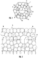
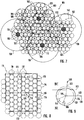
- FIG. 1 An elementary radio area 1 is shown in FIG. 1, which can be supplemented by stringing together identical radio areas 1 to form a nationwide radio network with an approximately honeycomb structure.
- a fixed transmission station 2 In the center of the radio area 1 there is a fixed transmission station 2, which is coupled to a radio concentrator (not shown) via cable or directional radio.
- the central transmitting station 2 supplies the inner radio zones 4a and 4b by means of two directional antennas with the range 3.
- a mobile station (not shown) communicates directly with the central transmission station 2.
- the central transmission station 2 is surrounded by decentralized transmission stations 5, which each have identical ranges 6.
- the ranges 6 of the decentralized radio stations 5 are approximately half as large as the range of the central radio station 2, which results from suitable dimensioning of the transmission powers.
- the ideally circular radio zones 7 of the decentralized transmission stations 5 have approximately half the radius as the central radio zone 4a, 4b.
- the decentralized transmitting stations 5 are arranged in such a way that their radio zones 7 complement one another to form two rings concentrically surrounding the central radio zone 4a, 4b.
- each of the decentralized radio zones 7 own transmission frequencies. Rather, in each case a plurality of adjacent transmission stations 5 can be combined to form radio areas 8, the border lines 9 of which are dashed in FIG. 1 are indicated.
- the decentralized transmission stations 5 of the radio zones 7 each assigned to the same radio area 8 communicate with the mobile stations at identical transmission frequencies.
- the radio area 1 shown in FIG. 1 accordingly has two central and six decentralized radio areas 4a, 4b, 8, in which different transmission frequencies are used in pairs.
- any number of radio areas 1 can be strung together to form a honeycomb radio network, the division of the individual radio areas 1 into radio areas 8 and the frequency assignments in the individual radio areas 8 being completely identical.
- radio area 10 shows a radio area 10 with a different basic structure.
- a central transmitting station 2 is surrounded by decentralized transmitting stations 5 in an approximately ring shape.
- radio area 10 does not have a hexagonal, but rather an approximately square basic shape.
- a multiplicity of square radio regions 10 are strung together to form a rectangular grid.
- the radio zones 7 of the individual, decentralized transmission stations 5 complement one another to form an approximately uniformly closed radio network 11.
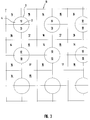
- FIG. 3 shows a larger section of the radio network 11, the individual radio zones 7 no longer being shown, but only the radio areas 12-17 within which constant transmission frequencies are used in each case. As can be seen, none of these radio areas 12-17 adjoins another radio area 12-17 with identical transmission frequencies.
- the radio range of the central transmitting stations 2 is divided into two with the aid of two directed 180 ° antennas Radio zones 12, 13 of different transmission frequencies are divided in order to achieve a greater range 3 of the central radio area 4. A total of six different radio ranges 12-17 are thus obtained, each with different transmission frequencies in pairs.
- the area of the radio zones 4a, 4b of the cost-intensive transmission stations 2 coupled to a radio concentrator corresponds to approximately one ninth of the total area.
- the number of these expensive transmission stations can be reduced to about a ninth, which more than makes up for the additional costs for the very simple, decentralized transmission stations.
- the total number of radio areas with different transmission frequencies in pairs with a total of six is significantly lower than with conventional lattice structures, where the hexagonal radio areas of a transmitting station are divided into three sectors by using directional 120 ° antennas, so that a total of twelve (quad structure with 3 sectors each) up to twenty-one (seven-way structure with 3 sectors each) radio areas with pairs of different transmission frequencies are formed.
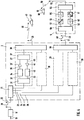
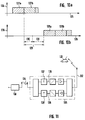
- FIG. 4 shows a block diagram of a central transmitting station 2 and, exceptionally, only one decentralized transmitting station 5.
- a radio concentrator 18 is shown, which is connected, for example, to a mobile switching center.
- the radio concentrator 18 communicates with the central transmission station 2 via a directional radio link 20.
- this transmission station 2 there is an interface module 21 which splits the signal received by the directional radio antenna 22 into individual transmission channels 23 to 26.
- a channel unit 27 to 30 is connected to each transmission channel 23-26.
- Each channel unit 27-30 comprises a connection module 31 which separates the relevant channel 23-26 depending on the transmission direction and consequently has two connections 32, 33 on the downlink side.
- the connection 32 which provides the signals arriving from the radio concentrator 18, is connected to an encoder 34, the output signal 35 of which is fed via an amplifier 36 to a bandpass filter assembly 37, from where the signal leaves the channel unit 27 and to a so-called combiner 38 is guided to be combined with the output signals of other channel units 28 and to be transmitted to an antenna 39 for area coverage of the central radio area.
- This transmission signal reaches the antenna 41 of a mobile station 42, for example in the form of a car telephone, via an air interface 40.
- the response signal of the mobile station 42 is transmitted in the opposite direction via the air interface 40 to the receiving device 39 of the central transmitting station 2, where it is assigned to the relevant channel unit 27, 28 via the combiner 38.
- the received signal 43 which has a different frequency than the transmitted signal 35, is separated from it and applied to the input of an amplifier 44.
- This is connected on the output side to a decoder 45, in which the received signal is processed and fed via the connection 33 to the connection module 31 of the relevant transmission channel 23, 24.
- the directional radio link 20 Via the interface module 21, the directional radio link 20, the radio concentrator 18 and the mobile switching center 19, the response signal is in the postal Telephone network fed.
- the coverage of the central radio area 4a, 4b hardly differs from conventional transmission devices, apart from a lower sectorization.
- channel units 29, 30 are provided in the central transmission station 2 according to the invention, which are connected to corresponding transmission channels 25, 26 of the interface module 21.
- the basic equipment of these channel units does not differ from conventional channel units 27, 28, but they have different transmission and reception frequencies.
- an antenna 47 with a highly directional characteristic is used here, so that the air interface 48 is designed as a true directional radio link, the up-link transmitting and receiving device 49 also being used the decentralized transmission station 5 has a corresponding, directed antenna.
- the directional antenna 49 is connected to a bandpass filter module 50 which, on the basis of the different frequencies, distinguishes the signal 51 arriving from the central transmission station 2 from the signal 52 directed to the central transmission station 2.
- the transmission signal 51 is fed to a frequency converter 53, the output frequency 54 of which corresponds to the transmission frequency of the radio area 8 in question.
- the transmission signal with the frequency 54 is now amplified in an amplifier 55 to a transmission power which guarantees the necessary range 6, and via a bandpass filter module 56 on the output side and a downstream one Transmitting and receiving device 57, emitted. Via the air interface 58, this transmission signal reaches the antenna 59 of a mobile station 60, which is currently located within the radio zone 7 of this decentralized transmission station 5.
- the response signal of this mobile station 60 is collected by the receiving device 57 and separated from the amplified transmit signal 54 by the bandpass filter module 56. Thereupon, it is transformed by a further frequency converter 61 into a frequency range 62 which is used for the directional radio link 48. After amplification by the amplifier 63, this signal 52 is fed to the directional radio antenna 49 via the input bandpass filter 50.
- the signal 48 emitted by this is received by the complementary directional radio antenna 47 of the central transmitting station 2 and from there is assigned in the combiner 46 to the corresponding channel unit 29, where, apart from other transmission frequencies, it is processed in exactly the same way as the signal 40 received by the antenna 39 in FIG inner radio zone 4.
- the response signal reaches the telephone network via the interface module 21, the directional radio link 20 and the radio concentrator 18.
- a timing element can be installed in the channel units 29, 30 communicating with a decentralized transmission station 5, which is started by the decoder 34 and only activates the encoder 45 after the set time interval has elapsed, in order to ensure the constant transit times on the directional radio link 48 to compensate.
- selection circuits are integrated in the additional channel units 29, 30, which have the signal amplitudes to be attributed to different reception field strengths on the downlink-side inputs 66, 67, the different directional radio antennas 47, 64 and thus different ones Transmit stations 5 are assigned, compare with each other and, when transmitting on the downlink side, select only the transmit antenna 47, 64 for which the highest received field strength has been registered. In this way, despite combining several radio zones 7 into a common radio area 8, only that transmitting station 5 is activated in whose radio zone 7 the mobile station 60 is currently located. The superimposition of several signals of the same frequency on the air interface 58 is thus avoided.
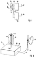
- FIG. 6 A structural design of a decentralized transmission station 5 is shown in FIG. 6.
- a flat housing 68 with a base area of approximately 1 square meter and a height of approximately 20 cm has an insertion device 70 for a transmission mast 71, approximately in the middle of its top 69, on which two Transmit and receive antennas 57, each with 180 ° directional characteristics. These antennas 57 are directed in opposite directions, so that they are a total Cover radio zone 7 with an approximately circular circumference. In order to reduce interference, the antennas 57 can be inclined downwards to converge by a small angle.
- the antennas 57 are connected to the housing 68 by means of connecting cables, not shown.
- a directional transmission and reception antenna 49 for the air interface 48 to a central transmission station 2 is mounted on a spaced post 72 and is connected to the housing 68 via a connecting cable 73. Due to the low transmission powers of the antennas 49, 57 and the minimal configuration of the electronic assemblies within the transmission station 5, the power supply can be ensured by means of solar cells which are arranged on the top 69 of the housing 68.
- FIG. 7 shows a section of a radio network 101.
- a large number of radio areas 102 can be seen, which are so seamlessly joined together that a single radio area assumes approximately the hexagonal shape of a single honeycomb 103.
- a circle with the radius 140 can be rewritten for each radio area 102.
- Radio areas 102 which adjoin one another each have different frequencies.
- the radio areas 102 marked with A can be operated in a first transmission frequency area
- the radio areas 102 provided with the character B are operated in a second transmission frequency area
- the radio areas 102 highlighted by C transmit in a third transmission frequency area.
- three transmission frequency ranges A, B and C are sufficient to get one To create radio network 101 with seamlessly adjacent radio areas 102, in each of which adjacent radio areas 102 are assigned to different transmission frequency areas A, B or C.
- each radio area 102 is divided into a total of seven radio zones 104.
- this is not mandatory. This is because the radio zones 104 do not have to be arranged within a radio area 102 according to a predetermined geometric grid, but are strung together in such a way that a complete coverage of the entire radio area 102 is ensured. It is also possible to create larger radio areas 102 in which a central radio zone 104 is not surrounded by a single ring composed of approximately six peripheral radio zones 104, but, for example, by two such rings, so that a total of approximately nineteen radio zones 104 per radio area 102 surrender.
- All transmission stations 105 of a radio area 102 are coupled to a radio concentrator (not shown) via a common connection station 108.
- a radio concentrator not shown
- several radio areas 102 are assigned to the same connection station 108.
- An approximately hexagonal structure 109 of the radio areas 102 connected to a common station 108 is preferably again suitable for this, but this is not mandatory.
- the potential locations 110 of the connection stations 108 can also be varied within the shaded area, for example, without the hexagonal structure 109 changing.
- the radio areas 112 have an approximately rectangular structure 113. How the radio zones 114 are arranged within these radio areas 112 is not important; however, a hexagonal structure similar to that shown in FIG. 7 is again suitable for this.
- the transmitting stations 115 are each in the center of a radio zone 114; the range 116 corresponds to the radius of these radio zones 114.
- the minimum distance 117 between two transmitting stations 115 from different radio ranges, but with the same transmission frequency range, is slightly larger than an edge of the rectangle 113. Nevertheless, due to the short ranges 116, this distance 117 is completely sufficient to ensure interference-free operation To ensure radio operation.
- several radio areas 112 are coupled to a radio concentrator (not shown) via a common connection station 118.
- connection station 108 For example, four radio areas 112 can be assigned to a connection station 108, so that their area of influence in any case has the shape of a rectangle 119.
- the location 120 of the connection station 118 can can be moved almost over the entire area of this rectangle 119 or even beyond this area if the connection is made via an antenna with a strongly directed characteristic. Nevertheless, the area in the center of the rectangle 119 is, of course, preferred, since there is a minimum running time of the connection signal for all the transmitting stations 115.
- a radio zone 104 is drawn out enlarged, which is located on the hexagonal edge 103 of its radio area 102.
- the adjacent transmission stations 105 emit the same radio signal, so that in the peripheral area 121 between two such adjacent transmission stations 5 there is a signal addition and thus an effective increase in the range 106 by, for example, about 15% to a radius 141.
- the distance 122 between adjacent transmitter stations 105 within the same radio area 102 must, however, only be smaller than twice that If the signal addition increases the radius 141 of a radio zone 104, the distance 122 between two transmitting stations 105 of the same radio area 102 can be dimensioned larger than the distance 123 to a transmitting station 105 in the adjacent radio area 102 'which is operated with a different transmission frequency range.
- the transmission signal 124 emitted by a connection station 108, 118 is plotted over the time axis 125, as is the signal 126 received by the same connection station 108, 118.
- the transmitted signals are correspondingly different Communication channels are divided into individual time blocks 127a, 127b, etc.
- the corresponding response signals of the addressed, fixed transmission stations 105, 115 are divided into the time blocks 128a, 128b etc. in accordance with the same channel division.
- a timer with the time constant 129 is started in the relevant connection station 118 and after this time constant 129 has elapsed, the receiving device of the relevant channel unit is activated in order to receive the response signal 128a of this channel.
- the time constant 129 comprises on the one hand the time 130, which corresponds to the waiting time set in conventional transmitting stations and, above all, takes into account the reaction time of a mobile station, and on the other hand an additional time interval 131, which above all doubles the signal delay between the relevant connection station 108, 118 and the furthest from this distant, but coupled to this stationary transmission station 105, 115 is taken into account.
- FIG. 11 shows a block diagram of a stationary transmission station 105.
- the antenna 132 for the area coverage of the assigned radio zone 104 can be seen, via which the communication to a mobile station 133 located in this radio zone 104 is established.
- there is an additional antenna 134 which is directed to the connection station 108 has directional characteristics. Since the directional radio link 134 in the exemplary embodiment shown is in the directional radio band, a frequency conversion within the transmitting station is necessary.
- This assembly therefore has almost the same structure as the decentralized transmitting station shown in FIG. 4 and labeled 5.
- an additional delay element 137, 138 is switched on both in the transmission branch 135 and in the reception branch 136 of the stationary transmission station 105.
- the time constants T of the delay elements 137, 138 can be set in a range which corresponds approximately to the additional time interval 131 of the relevant connection station 108.
- the time constants T of the delay elements 137, 138 of the transmitting stations 105 furthest away from the connecting station 108 By setting the time constants T of the delay elements 137, 138 of the transmitting stations 105 furthest away from the connecting station 108 to zero, for the nearest transmitting stations 105, on the other hand, about half the time interval 131, care can be taken to ensure that this is done by the connecting station 108 received signal is emitted from all transmitting stations 105 of the same radio area 102 at the same time via the area-covering antenna 132, so that the desired signal addition results in the peripheral area 121.
- the signal emitted by the mobile station 133 in response can also be emitted synchronously via the directional antennas 134 to the connection station 108, provided this is received by a plurality of transmitting stations 105.
Landscapes
- Engineering & Computer Science (AREA)
- Computer Networks & Wireless Communication (AREA)
- Signal Processing (AREA)
- Mobile Radio Communication Systems (AREA)
- Input Circuits Of Receivers And Coupling Of Receivers And Audio Equipment (AREA)
- Non-Insulated Conductors (AREA)
Applications Claiming Priority (4)
| Application Number | Priority Date | Filing Date | Title |
|---|---|---|---|
| DE4422490 | 1994-06-28 | ||
| DE19944422490 DE4422490C1 (de) | 1994-06-28 | 1994-06-28 | Anordnung ortsfester Sendestationen eines flächendeckenden Funknetzes sowie ortsfeste Sendestationen und Verfahren zum nachträglichen Verdichten eines bestehenden flächendeckenden Funknetzes |
| DE19501603 | 1995-01-20 | ||
| DE19501603 | 1995-06-20 |
Publications (3)
| Publication Number | Publication Date |
|---|---|
| EP0690643A2 true EP0690643A2 (fr) | 1996-01-03 |
| EP0690643A3 EP0690643A3 (fr) | 1996-04-24 |
| EP0690643B1 EP0690643B1 (fr) | 2000-11-02 |
Family
ID=25937772
Family Applications (1)
| Application Number | Title | Priority Date | Filing Date |
|---|---|---|---|
| EP95108281A Expired - Lifetime EP0690643B1 (fr) | 1994-06-28 | 1995-05-31 | Arrangement de stations de base pour réseau radio à couverture par zones |
Country Status (4)
| Country | Link |
|---|---|
| EP (1) | EP0690643B1 (fr) |
| AT (1) | ATE197368T1 (fr) |
| DE (1) | DE59508816D1 (fr) |
| ES (1) | ES2153445T3 (fr) |
Cited By (3)
| Publication number | Priority date | Publication date | Assignee | Title |
|---|---|---|---|---|
| WO1997044967A2 (fr) * | 1996-05-21 | 1997-11-27 | Telefonaktiebolaget Lm Ericsson (Publ) | Systeme de transmission dynamique par reseau radio de base |
| WO2002007471A1 (fr) * | 2000-07-14 | 2002-01-24 | Ip.Access Ltd. | Systemes cellulaires de telecommunications radio |
| CN116074852A (zh) * | 2023-03-06 | 2023-05-05 | 长沙迪迈数码科技股份有限公司 | Uwb定位基站布置方法、装置、设备及存储介质 |
Family Cites Families (3)
| Publication number | Priority date | Publication date | Assignee | Title |
|---|---|---|---|---|
| DE3528974A1 (de) * | 1985-08-13 | 1987-02-26 | Bosch Gmbh Robert | Funktelefonnetz fuer ein in funkzellen aufgeteiltes funkgebiet |
| CA2008900C (fr) * | 1989-04-04 | 1998-01-20 | Ta-Shing Chu | Radio mobile microcellulaire a fibre optique |
| EP0657074B1 (fr) * | 1992-08-26 | 1998-10-21 | Siemens Aktiengesellschaft | Reseau radiophonique mobile |
-
1995
- 1995-05-31 AT AT95108281T patent/ATE197368T1/de not_active IP Right Cessation
- 1995-05-31 DE DE59508816T patent/DE59508816D1/de not_active Expired - Fee Related
- 1995-05-31 ES ES95108281T patent/ES2153445T3/es not_active Expired - Lifetime
- 1995-05-31 EP EP95108281A patent/EP0690643B1/fr not_active Expired - Lifetime
Non-Patent Citations (1)
| Title |
|---|
| None |
Cited By (4)
| Publication number | Priority date | Publication date | Assignee | Title |
|---|---|---|---|---|
| WO1997044967A2 (fr) * | 1996-05-21 | 1997-11-27 | Telefonaktiebolaget Lm Ericsson (Publ) | Systeme de transmission dynamique par reseau radio de base |
| WO1997044967A3 (fr) * | 1996-05-21 | 1997-12-31 | Ericsson Telefon Ab L M | Systeme de transmission dynamique par reseau radio de base |
| WO2002007471A1 (fr) * | 2000-07-14 | 2002-01-24 | Ip.Access Ltd. | Systemes cellulaires de telecommunications radio |
| CN116074852A (zh) * | 2023-03-06 | 2023-05-05 | 长沙迪迈数码科技股份有限公司 | Uwb定位基站布置方法、装置、设备及存储介质 |
Also Published As
| Publication number | Publication date |
|---|---|
| EP0690643B1 (fr) | 2000-11-02 |
| EP0690643A3 (fr) | 1996-04-24 |
| ATE197368T1 (de) | 2000-11-15 |
| DE59508816D1 (de) | 2000-12-07 |
| ES2153445T3 (es) | 2001-03-01 |
Similar Documents
| Publication | Publication Date | Title |
|---|---|---|
| DE69511598T2 (de) | Antenneneinrichtung für Basisstation | |
| DE69504867T2 (de) | Richtantennensystem | |
| DE69827250T2 (de) | Steuerung von sende-empfänger-einheiten in einem zellularen funksystem | |
| US6128496A (en) | Cellular transceiver station with adjustable time lag | |
| DE69032053T2 (de) | Antennen-Umschaltsystem | |
| DE60122119T2 (de) | Distributives intelligentes antennensystem | |
| DE4141398C2 (de) | Verfahren zum Verbessern der Funkzellenausleuchtung bei eimen zellularen Mobilfunksystem und Vorrichtung zum Ausüben des Verfahrens | |
| DE69432453T2 (de) | Verfahren zur Funkverbindungssteuerung für ein Mobiltelekommunikationssystem | |
| DE68923509T2 (de) | Sektoren-zellulares Kommunikationssystem mit hoher Kapazität. | |
| DE1591811C3 (de) | Satelliten-Antennensystem | |
| DE68925821T2 (de) | Verfahren und system für ein grossflächen-funkkommunikationssystem | |
| EP1444851B1 (fr) | Procede pour transmettre des informations dans un systeme de radiocommunication cellulaire presentant des secteurs radio et systeme de radiocommunication cellulaire | |
| DE69205993T2 (de) | Zellulares funksystem. | |
| DE69230015T2 (de) | Kommunikationssystem mit Hilfe von Satelliten in niedriger Umlaufbahn zu Mobilstationen | |
| EP1188261A1 (fr) | Transitions alternantes de liaison montante/descendante lors de l'attribution de canaux dans une trame de transmission drt avec plusieurs instants de commutation | |
| EP0690643B1 (fr) | Arrangement de stations de base pour réseau radio à couverture par zones | |
| DE60127714T2 (de) | System und verfahren zur frequenzwiederverwendung in einem sektorisierten zellenmuster in einem drahtlosen kommunikationssystem | |
| EP1760917B1 (fr) | Procédé et dispositif pour la configuration des n utilisateurs indépendents d'une installation de réception de satellite | |
| DE4422490C1 (de) | Anordnung ortsfester Sendestationen eines flächendeckenden Funknetzes sowie ortsfeste Sendestationen und Verfahren zum nachträglichen Verdichten eines bestehenden flächendeckenden Funknetzes | |
| DE2659570C2 (de) | Fernsprech- und Datennetz für ortsfeste und mobile Teilnehmerstationen | |
| DE4225582C2 (de) | Verfahren zur Verbesserung der Funkversorgung einer Verkehrswegestruktur durch ein zellulares Mobilfunksystem und Vorrichtung zur Ausübung des Verfahrens | |
| EP0734194B1 (fr) | Réseau de radio-communications avec illumination centrale par antennes sectorielles | |
| DE3049011C2 (fr) | ||
| DE4238295A1 (de) | Mobilfunknetz und Funkfeststation dafür | |
| DE10032602A1 (de) | Zellulares Funksystem |
Legal Events
| Date | Code | Title | Description |
|---|---|---|---|
| PUAI | Public reference made under article 153(3) epc to a published international application that has entered the european phase |
Free format text: ORIGINAL CODE: 0009012 |
|
| AK | Designated contracting states |
Kind code of ref document: A2 Designated state(s): AT CH DE ES FR GB IT LI SE |
|
| PUAL | Search report despatched |
Free format text: ORIGINAL CODE: 0009013 |
|
| RBV | Designated contracting states (corrected) |
Designated state(s): AT CH DE ES FR GB IT LI SE |
|
| AK | Designated contracting states |
Kind code of ref document: A3 Designated state(s): AT BE CH DE DK ES FR GB GR IE IT LI LU MC NL PT SE |
|
| 17P | Request for examination filed |
Effective date: 19960531 |
|
| RAP1 | Party data changed (applicant data changed or rights of an application transferred) |
Owner name: WORLDWIDE WIRELESS HOLDING LLC |
|
| RIN1 | Information on inventor provided before grant (corrected) |
Inventor name: SCHEINERT, STEFAN |
|
| RAP1 | Party data changed (applicant data changed or rights of an application transferred) |
Owner name: LITTLEFEET, INC. |
|
| GRAG | Despatch of communication of intention to grant |
Free format text: ORIGINAL CODE: EPIDOS AGRA |
|
| GRAG | Despatch of communication of intention to grant |
Free format text: ORIGINAL CODE: EPIDOS AGRA |
|
| GRAH | Despatch of communication of intention to grant a patent |
Free format text: ORIGINAL CODE: EPIDOS IGRA |
|
| 17Q | First examination report despatched |
Effective date: 20000118 |
|
| GRAH | Despatch of communication of intention to grant a patent |
Free format text: ORIGINAL CODE: EPIDOS IGRA |
|
| GRAA | (expected) grant |
Free format text: ORIGINAL CODE: 0009210 |
|
| AK | Designated contracting states |
Kind code of ref document: B1 Designated state(s): AT CH DE ES FR GB IT LI SE |
|
| REF | Corresponds to: |
Ref document number: 197368 Country of ref document: AT Date of ref document: 20001115 Kind code of ref document: T |
|
| REG | Reference to a national code |
Ref country code: CH Ref legal event code: EP |
|
| REF | Corresponds to: |
Ref document number: 59508816 Country of ref document: DE Date of ref document: 20001207 |
|
| ITF | It: translation for a ep patent filed | ||
| GBT | Gb: translation of ep patent filed (gb section 77(6)(a)/1977) |
Effective date: 20010202 |
|
| REG | Reference to a national code |
Ref country code: CH Ref legal event code: NV Representative=s name: SIEMENS SCHWEIZ AG |
|
| REG | Reference to a national code |
Ref country code: ES Ref legal event code: FG2A Ref document number: 2153445 Country of ref document: ES Kind code of ref document: T3 |
|
| ET | Fr: translation filed | ||
| PLBE | No opposition filed within time limit |
Free format text: ORIGINAL CODE: 0009261 |
|
| STAA | Information on the status of an ep patent application or granted ep patent |
Free format text: STATUS: NO OPPOSITION FILED WITHIN TIME LIMIT |
|
| 26N | No opposition filed | ||
| REG | Reference to a national code |
Ref country code: GB Ref legal event code: IF02 |
|
| PG25 | Lapsed in a contracting state [announced via postgrant information from national office to epo] |
Ref country code: IT Free format text: LAPSE BECAUSE OF NON-PAYMENT OF DUE FEES;WARNING: LAPSES OF ITALIAN PATENTS WITH EFFECTIVE DATE BEFORE 2007 MAY HAVE OCCURRED AT ANY TIME BEFORE 2007. THE CORRECT EFFECTIVE DATE MAY BE DIFFERENT FROM THE ONE RECORDED. Effective date: 20050531 |
|
| PGFP | Annual fee paid to national office [announced via postgrant information from national office to epo] |
Ref country code: ES Payment date: 20080522 Year of fee payment: 14 Ref country code: DE Payment date: 20080617 Year of fee payment: 14 Ref country code: CH Payment date: 20080520 Year of fee payment: 14 |
|
| PGFP | Annual fee paid to national office [announced via postgrant information from national office to epo] |
Ref country code: AT Payment date: 20080516 Year of fee payment: 14 |
|
| PGFP | Annual fee paid to national office [announced via postgrant information from national office to epo] |
Ref country code: SE Payment date: 20080519 Year of fee payment: 14 |
|
| PGFP | Annual fee paid to national office [announced via postgrant information from national office to epo] |
Ref country code: GB Payment date: 20080519 Year of fee payment: 14 |
|
| REG | Reference to a national code |
Ref country code: CH Ref legal event code: PCAR Free format text: SIEMENS SCHWEIZ AG;INTELLECTUAL PROPERTY FREILAGERSTRASSE 40;8047 ZUERICH (CH) |
|
| REG | Reference to a national code |
Ref country code: CH Ref legal event code: NV Representative=s name: ISLER & PEDRAZZINI AG |
|
| REG | Reference to a national code |
Ref country code: CH Ref legal event code: PL |
|
| GBPC | Gb: european patent ceased through non-payment of renewal fee |
Effective date: 20090531 |
|
| PG25 | Lapsed in a contracting state [announced via postgrant information from national office to epo] |
Ref country code: LI Free format text: LAPSE BECAUSE OF NON-PAYMENT OF DUE FEES Effective date: 20090531 Ref country code: CH Free format text: LAPSE BECAUSE OF NON-PAYMENT OF DUE FEES Effective date: 20090531 Ref country code: AT Free format text: LAPSE BECAUSE OF NON-PAYMENT OF DUE FEES Effective date: 20090531 |
|
| REG | Reference to a national code |
Ref country code: FR Ref legal event code: ST Effective date: 20100129 |
|
| PG25 | Lapsed in a contracting state [announced via postgrant information from national office to epo] |
Ref country code: FR Free format text: LAPSE BECAUSE OF NON-PAYMENT OF DUE FEES Effective date: 20090602 |
|
| PGFP | Annual fee paid to national office [announced via postgrant information from national office to epo] |
Ref country code: IT Payment date: 20080526 Year of fee payment: 14 Ref country code: FR Payment date: 20080519 Year of fee payment: 14 |
|
| PGRI | Patent reinstated in contracting state [announced from national office to epo] |
Ref country code: IT Effective date: 20091201 |
|
| PG25 | Lapsed in a contracting state [announced via postgrant information from national office to epo] |
Ref country code: GB Free format text: LAPSE BECAUSE OF NON-PAYMENT OF DUE FEES Effective date: 20090531 |
|
| PG25 | Lapsed in a contracting state [announced via postgrant information from national office to epo] |
Ref country code: DE Free format text: LAPSE BECAUSE OF NON-PAYMENT OF DUE FEES Effective date: 20091201 |
|
| REG | Reference to a national code |
Ref country code: ES Ref legal event code: FD2A Effective date: 20090601 |
|
| PG25 | Lapsed in a contracting state [announced via postgrant information from national office to epo] |
Ref country code: ES Free format text: LAPSE BECAUSE OF NON-PAYMENT OF DUE FEES Effective date: 20090601 |
|
| PGRI | Patent reinstated in contracting state [announced from national office to epo] |
Ref country code: IT Effective date: 20091201 |
|
| PG25 | Lapsed in a contracting state [announced via postgrant information from national office to epo] |
Ref country code: SE Free format text: LAPSE BECAUSE OF NON-PAYMENT OF DUE FEES Effective date: 20090601 |