EP0689175B1 - Check out system for identifying and registering articles - Google Patents
Check out system for identifying and registering articles Download PDFInfo
- Publication number
- EP0689175B1 EP0689175B1 EP95108210A EP95108210A EP0689175B1 EP 0689175 B1 EP0689175 B1 EP 0689175B1 EP 95108210 A EP95108210 A EP 95108210A EP 95108210 A EP95108210 A EP 95108210A EP 0689175 B1 EP0689175 B1 EP 0689175B1
- Authority
- EP
- European Patent Office
- Prior art keywords
- article
- image
- checkout
- articles
- customer
- Prior art date
- Legal status (The legal status is an assumption and is not a legal conclusion. Google has not performed a legal analysis and makes no representation as to the accuracy of the status listed.)
- Expired - Lifetime
Links
Images


Classifications
-
- A—HUMAN NECESSITIES
- A47—FURNITURE; DOMESTIC ARTICLES OR APPLIANCES; COFFEE MILLS; SPICE MILLS; SUCTION CLEANERS IN GENERAL
- A47F—SPECIAL FURNITURE, FITTINGS, OR ACCESSORIES FOR SHOPS, STOREHOUSES, BARS, RESTAURANTS OR THE LIKE; PAYING COUNTERS
- A47F9/00—Shop, bar, bank or like counters
- A47F9/02—Paying counters
- A47F9/04—Check-out counters, e.g. for self-service stores
- A47F9/046—Arrangement of recording means in or on check-out counters
- A47F9/047—Arrangement of recording means in or on check-out counters for recording self-service articles without cashier or assistant
- A47F9/048—Arrangement of recording means in or on check-out counters for recording self-service articles without cashier or assistant automatically
-
- A—HUMAN NECESSITIES
- A47—FURNITURE; DOMESTIC ARTICLES OR APPLIANCES; COFFEE MILLS; SPICE MILLS; SUCTION CLEANERS IN GENERAL
- A47F—SPECIAL FURNITURE, FITTINGS, OR ACCESSORIES FOR SHOPS, STOREHOUSES, BARS, RESTAURANTS OR THE LIKE; PAYING COUNTERS
- A47F9/00—Shop, bar, bank or like counters
- A47F9/02—Paying counters
- A47F9/04—Check-out counters, e.g. for self-service stores
- A47F9/046—Arrangement of recording means in or on check-out counters
-
- G—PHYSICS
- G07—CHECKING-DEVICES
- G07G—REGISTERING THE RECEIPT OF CASH, VALUABLES, OR TOKENS
- G07G1/00—Cash registers
- G07G1/0036—Checkout procedures
- G07G1/0045—Checkout procedures with a code reader for reading of an identifying code of the article to be registered, e.g. barcode reader or radio-frequency identity [RFID] reader
- G07G1/0054—Checkout procedures with a code reader for reading of an identifying code of the article to be registered, e.g. barcode reader or radio-frequency identity [RFID] reader with control of supplementary check-parameters, e.g. weight or number of articles
Definitions
- This invention relates to a checkout system for recognizing an article based on the article code affixed to the respective article.
- POS Point of Sales
- a checkout apparatus used as a terminal of the POS system is disclosed in Jpn. Pat. KOKAI Publication No. 4-67291.
- a bar code scanner 1 is arranged between a carry-in conveyor 2 and a carry-out conveyor 3 and an electronic cash register 4 is disposed near one side of the carry-out conveyor 3.
- the bar code scanner 1 has a keyboard 1a for inputting an article code and a display 1b for displaying the result of inputting.
- the customer places the articles on the carry-in conveyor 2 one by one and then moves towards the carry-out conveyor 3 as indicated by an arrow.
- the carry-in conveyor 2 sequentially carries the articles placed one at a time by the customer 10 towards the bar code scanner 1.
- An article sensor 5 detects an article carried to the end portion of the carry-in conveyor 2 which is adjacent to the bar code scanner 1.
- the carry-in conveyor 2 stops at the time of detection of the article and is driven again to carry the next article after the article is taken up from the carry-in conveyor 2 by an operator 6.
- the operator 6 puts the article in a scanning range of the bar code scanner 1 so as to permit the bar code scanner 1 to read the article code affixed to the taken-up article in the bar code form. If the article code is not affixed to the article or the bar code scanner 1 fails to read the article code, the article code is input to the bar code scanner 1 by use of the keyboard 1a.
- the carry-out conveyor 3 carries the article placed thereon by the operator in a direction away from the bar code scanner 1.
- the electronic cash register 4 registers the sales article based on the article code supplied from the bar code scanner 1, derives the total sum of money for all of the sold articles when the operator 8 operates the total key, and issues a receipt having the total sum of money printed thereon.
- the customer 10 pays money for the articles to the operator 8, moves the purchased articles from the carry-out conveyor 3 into the shopping cart 11, and then leaves the checkout apparatus.
- the driving speeds of the carry-in conveyor 2 and carry-out conveyor 3 can be adjusted by use of control switches 7 and 9 which are respectively disposed near the operators 6 and 8.
- a partition rod 12 is used to separate the purchased articles for respective customers 10 and previously placed near the carry-in conveyor 2.
- the customer 10 puts the partition rod 12 on the carry-in conveyor 2 after all of the articles purchased by the customer are placed.
- the operator 6 moves the partition rod 12 from the carry-in conveyor 2 to the carry-out conveyor 3 and the operator 8 recognizes that the partition rod 12 is carried on the carry-out conveyor 3 and then operates the total key of the electronic cash register 4.
- US 5 115 888 A discloses a checkout system in which a customer scans a bar code affixed to an article and registers the article. If an article does not have a bar code affixed to it, a customer takes an image of the article using a camera. Then, a supervisory employee at a remote terminal looks at the image of the article and registers the article.
- US 4 920 255 A discloses a scanner system which comprises a range detector, scanner, and control circuit.
- the range detector measures the range of an article relative to the scanner.
- the control circuit adjusts the focal length of the scanner based on measured range to enable accurate reading of a code pattern on the article.
- the range detector is disposed upstream of the scanner. However, the range detector is unable to capture an image from which physical features of the article such as a size, shape, place position, and article code position of the article are extracted.
- the bar code affixed to an article is read using a bar code scanner while the article is transferred on a conveyer belt.
- An image of an article whose bar code is not successfully read by the bar code scanner is taken using a camera.
- the article is registered either by means of pattern recognition or by a human being who checks the image of the article displayed at a remote terminal..
- An object of this invention is to provide a checkout system in which the number of operators required for rapidly and stably registering articles can be reduced without increasing the load of the operator.
- a checkout system comprising:
- an article placed on a transfer means is automatically registered by either one of the following methods:
- the auxiliary registering means registers the article. That is, only the article that cannot be recognized by the article registering means is registered by the control of the remote terminal device. In this case, since it is not necessary for the operator to receive an unregistered article from the customer, the article can be rapidly and stably registered without increasing the load of the operator. Further, even when the number of checkout lanes is increased, all of the checkout lanes can be managed by one operator.
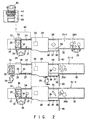
- FIG. 2 shows a checkout system according to a first embodiment of this invention.
- the checkout system has three checkout lanes 21-1, 21-2 and 21-3 and a remote terminal device 41 arranged at a preset distance from the checkout lane.
- Each of the checkout lanes 21-1, 21-2 and 21-3 and the remote terminal device 41 are connected via a line 42 and signals and image data are transferred via the line 42.
- a basket placing table 23 for placing a shopping basket 22 thereon, a belt conveyor 24 for carrying an article 26 from the upstream side to the downstream side, and an article stacker 32 for storing an article 26a carried are sequentially arranged from one end of the checkout lane.
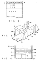
- An article placing area 27 for permitting a customer 25 to take out an article 26 from the shopping basket 22 and place the article on the area is provided on the upstream side portion of the belt conveyor 24. Further, on the intermediate portion of the belt conveyor 24, a tunnel portion 28 is provided. In the tunnel portion 28, a height measuring apparatus 29 for measuring the height of an article, a video camera 30 for obtaining an image of an article carried by the belt conveyor 24 and a bar code scanner 31 having a variable scanning optical system for reading a bar code affixed on the article are arranged as shown in FIG. 5.
- the height measuring apparatus 29 has two support poles 101 and 102 arranged to face each other with the belt conveyor 24 as a carrying path for the article 26 disposed therebetween.
- the support pole 101 has a plurality of light emitting elements 103, --- formed of LEDs or the like arranged at a preset pitch.
- the other support pole 102 has a plurality of light receiving elements 104, --- formed of phototransistors or photodiodes arranged at a preset pitch to face the respective light emitting elements 103, ---.
- light beams emitted from the light emitting elements 103 towards the light receiving elements 104 are interrupted by the article 26 carried on the belt conveyor 24 and the height of the article 26 can be measured based on the number of light receiving elements 104 which cannot receive the light beam.
- the video camera 30 is arranged directly above an image input area 100 to monitor the entire portion of the image input area 100 on the belt conveyor 24 or obtain an image of an article passing through the image input area 100.
- the features of an article such as the position, size, shape and color of the article can be extracted by subjecting the image of the article obtained by the video camera 30 to the image processing. At this time, the position and inclination of the bar code affixed on the article are detected.
- the bar code scanner 31 reads the bar code affixed to an article passing through a scanning area 105 on the belt conveyor 24 and decodes article code information.
- the bar code scanner 31 has variable scanning optical systems 106, 107, 108 including laser light sources such as semiconductor lasers arranged on both sides of and above the scanning area 105.
- the optical length, focal distance and scanning pattern of the variable scanning optical systems 106, 107, 108 can be changed. Therefore, the variable scanning optical systems 106, 107, 108 can selectively and concentratedly scan a portion including the bar code affixed to the article based on the result of height measurement by the height measuring apparatus 29 and results obtained by processing the image from the video camera 30 so as to rapidly and stably read the bar code.
- the article code information decoded by the bar code scanner 31 is registered into the POS terminal as will be described later.
- a start button 33 for indicating that the placement of the article is started and an end button 34 for indicating that the placement of the article is ended are disposed on one corner portion of the basket placing table 23.
- a panel display 35 for displaying the contents of the operation for the customer is disposed on one side of the basket placing table 23 opposite to the customer 25.
- a speaker for informing the guidance in a voice is also disposed on one corner portion of the basket placing table 23.
- An Automatic Teller's Machine (ATM) 39 is disposed on the side of the passage for the customer 25 on the downstream side of the belt conveyor 24 provided in each of the checkout lanes 21-1, 21-2, 21-3.
- the ATM 39 has a sub-total display 36 for displaying the total sum of money for the registered articles 26a, an automatic payment machine 37 having an insertion port into which a pre-paid card, credit card or cash is inserted, for effecting the automatic payment process and giving back change from a change discharging port if the payment is made by cash and change is made, and a receipt issuing machine 38 for printing the article names and prices of the registered articles, the number of articles and the total amount of money on paper and issuing a receipt.
- a gate 40 is disposed on the passage of each of the checkout lanes 21-1, 21-2, 21-3.
- the gate 40 is disposed on the passage in a boundary portion between the downstream side of the belt conveyor 24 and the article stacker 32 for storing the registered articles.
- the gate 40 is normally set in a state to block up the passage and locked in this state.
- the gate 40 is released from the locked state when the customer 25 has made the payment by use of the automatic payment machine 37 and the receipt issuing machine 38 has issued a receipt, and after the customer has passed through the gate in the lock releasing state, the gate is closed again to block up the passage and locked in this state.
- the remote terminal device 41 disposed in a preset position has a monitor display 43 for receiving image data of unregistered articles from each of the checkout lanes 21-1, 21-2, 21-3 and displaying the image data, a keyboard 44 for inputting the article name or article code of the article displayed on the monitor display 43, and an alarming device for receiving an alarm signal from each of the checkout lanes 21-1, 21-2, 21-3 and effecting the alarming operation.
- the remote terminal device 41 is operated by the operator 45.
- the alarming device a sound generation device having a speaker, a indicator or a device for displaying an alarm message on the monitor display 43 is used.
- FIG. 3 shows a Point of Sales (POS) terminal 200 contained in each of the checkout lanes 21-1, 21-2, 21-3.
- the POS terminal 200 has a memory for registering or accumulating the number of sold articles and the amount of money of the sold articles based on article code information decoded by the bar code scanner 31. Further, the POS terminal 200 is connected to a host computer set in an office of the store, for example, and all the sales information in the store is managed by use of the host computer. Further, the POS terminal 200 also functions as a control circuit for controlling the components of the corresponding checkout lane 21-1, 21-2, 21-3.
- the POS terminal 200 has a CPU 202 for controlling the components of the checkout lane.
- the CPU 202 is connected to a ROM 204 in which initialization data and control programs for the components are stored and a RAM 206 having a first counter 46, second counter 47, video RAM area and work area as shown in FIG. 4.
- the start button 33 and end button 34 disposed on the upstream side of the belt conveyor 24 are connected to the CPU 202 via an interface 208.
- the panel display 35 and speaker 49 are connected to the CPU 202 via a controller 210 and driver 212, respectively.
- the conveyor 24 is connected to the CPU 202 via a driver 214.
- the height measuring apparatus 29, video camera 30 and bar code scanner 31 of the tunnel portion 28 disposed near the intermediate portion of the conveyor 24 are connected to the CPU 202 via respective interfaces 216, 218, 220.
- the ATM 39 and gate 40 disposed on the downstream side of the conveyor 24 are connected to the CPU 202 via a controller 222 and driver 224, respectively.
- monitor display 43 and keyboard 44 of the remote terminal device 41 are connected to a CPU 202 of the POS terminal 200 via respective controllers 226, 228.
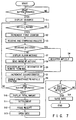
- the CPU 202 provided in the POS terminal 200 of each of the checkout lanes 21-1, 21-2, 21-3 causes the panel display 35 to display the guidance for the start of the operation for the customer, starts to drive the belt conveyor 24 and clears the content of the first counter (S1) when the start button 33 is depressed by the customer 25.
- an article 26 is placed on the article placing area 27 by the customer and carried to the downstream side by the belt conveyor 24.
- the article 26 passes the tunnel portion 28 and is detected by the CPU 202 via the height measuring apparatus 29 or video camera 30, the content of the first counter 46 is incremented (S2).
- the height of the article 26 is first measured by the height measuring apparatus 29 and then an image of the article is obtained by the video camera 30.
- the operation of reading the bar code affixed on the article 26 is effected (S3). That is, the height, size and position of the article 26 are recognized based on information from the height measuring apparatus 29 and video camera 30, the focal distance, scanning pattern and direction of the bar code scanner 31 are determined and an effective area (position in which the bar code is present) of the article is scanned by the bar code scanner 31. Then, the bar code is read by the bar code scanner 31 and transferred to the POS terminal 200. At this time, the feature data of the article derived by the height measuring apparatus 29 and video camera 30 is transferred to the POS terminal 200. The comparing process with data of the data base in the RAM 206 is effected based on the transferred code and feature data of the article.
- the article code is decoded in the reading and comparing process S3
- the article code is registered into the work area of the RAM 206 (S4) and the content of the second counter 47 is incremented (S5).
- the thus registered article is carried as a registered article 26a to the article stacker 32 by the belt conveyor 24 (S6).
- an alarm signal is supplied to the remote terminal device 41 via the line 42 (S7).
- the CPU 202 temporarily interrupts the operation of the belt conveyor 24.
- the remote terminal device 41 receives the alarm signal to sound a buzzer, light a lamp, or display caution on the monitor display 43, thereby informing the operator 45 of one of the checkout lanes in which an unregistered article caused by the impossibility of reading is present.
- image data of the unregistered article is transferred to the remote terminal device 41 via the line 42 (S8).
- the remote terminal device 41 receives the image data and the image of the unregistered article is displayed on the monitor display 43.
- the operator 45 recognizes the image of the article displayed on the monitor display 43 and operates the keyboard 44 to input the article name or article code of the displayed article and the information is transferred to the POS terminal 200 of the corresponding checkout lane via the line 42.
- the article code of the unregistered article is registered into the RAM 206 of the POS terminal 200 (S9).
- the content of the second counter 47 is incremented (S5) and the belt conveyor 24 is driven again (S6) to carry the article to the article stacker 32 as a registered article 26a.
- steps S2 to S9 are repeatedly effected until the end button 34 is depressed by the customer 25.
- the content of the first counter 46 and the content of the second counter 47 are compared with each other after the process for registering all of the articles placed on the belt conveyor 24 is effected. If the content of the first counter 46 coincides with the content of the second counter 47, the CPU 202 determines that all of the articles have been registered and displays the total amount of money for the articles on the sub-total display 36 (S10). Further, the content of the second counter 47 is cleared.
- the settlement process that is, cash registration process is effected (S11). More specifically, the customer 25 inserts the pre-paid card, credit card or cash into the automatic payment machine 37 to effect the payment process. In the case of settlement by cash, a change is calculated and a change is given, if any.
- the CPU 202 causes the receipt issuing machine 38 to print the article names, prices, and the number of registered articles and issue a receipt having the total amount printed thereon (S12).
- the locked state of the gate 40 is released to open the passage (S13).
- the gate 40 is closed to block up the passage and is locked in this state (S14).
- a sequence of article registration control operations is ended, and the CPU 202 sets the initial condition so as to start the operation of the checkout lane for a next customer.
- the remote terminal device 41 receives the image data and the image of the article is displayed on the monitor display 43, but an image obtained by processing the image and extracting feature data of the article may be displayed. Further, it is possible to first compare the feature data of the article with data of the data base and display a candidate of a corresponding article name.
- the data base is previously created by taking into consideration the conditions such as the position and inclination of the article 26 set when the customer 25 places the article 26 on the belt conveyor 24. That is, the data base is created by extracting a large number of feature data items such as the sizes (projected areas), shapes, and colors of all of the articles (in some cases, part of articles such as fresh foods may be excluded) by the image processing and registering the same.
- the feature data of color is constructed by monochromatic data, color component data indicating red, green or blue, chromatic data representing hue, brightness and chroma, or other color data.
- the feature data of the article 26 is extracted for each item such as the size and shape by first measuring the height of the article 26 carried by the belt conveyor 24 by use of the height measuring apparatus 29, obtaining an image of the article by the video camera 30 and subjecting the image to the image processing (S21).
- the feature data of the article corresponding to the decoded article code is derived from the data base and the comparing process with the feature data of the article subjected to the image processing in S21 is effected (S22). If it is detected in the comparing process that no feature data which coincides with or approximately equal to the corresponding feature data is present in the data base, the feature data is additionally registered as the feature data of the corresponding article of the data base (S23). If feature data which coincides with or approximately equal to the corresponding feature data is present, the comparing process is completed and the article whose article code is decoded is registered in S4 shown in FIG. 7.
- the feature data of the article obtained by the image processing is sequentially compared with feature data of all of the articles in the data base (S24). If it is detected in the comparing process that an article having a feature which is sufficiently similar to that represented by the feature data of the article is present in the data base, the article code of the article having the coincident feature data is read from the data base (S25). Then, the comparing process is terminated and the article is registered in S4 shown in FIG. 7 based on the readout article code.
- the customer 25 effects a sequence of operations for registration according to the following operation sequence.
- the customer 25 goes to one end side of one of the checkout lanes, for example, the checkout lane 21-1 with the articles 26 received in the shopping basket 22. Then, the customer 25 places the shopping basket 22 on the basket placing table 23. At this time, the panel display 35 displays a message instructing the customer 25 to depress the start button 33 so as to start the checkout operation. Further, the same instruction is also given in a voice. If the customer 25 depresses the start button 33 according to the instruction, the belt conveyor 24 is driven. At this time, the content of the first counter is cleared.
- the customer 25 receives an instruction that the article 26 should be placed on the article placing area 27 with the bar code affixed to the article set to face upward or sideways according to the message displayed on the panel display 35 and the voice from the speaker 49. Therefore, the customer 25 takes out the articles 26 one by one from the shopping basket 22, and effects the operation of placing the article on the article placing area 27 after recognizing the position of the bar code. During this operation, the customer 25 receives an instruction that the end button 34 should be depressed after all of the articles 26 have been placed according to the message on the panel display 35 and the voice.
- the article 26 placed on the belt conveyor 24 is carried to the tunnel portion 28.
- the height of the article 26 is measured by the height measuring apparatus 29, an image of the article is obtained by the video camera 30, and the image of the article is subjected to the image processing by the CPU 202.
- the content of the first counter 46 is incremented.
- the focal distance, scanning pattern and direction of the bar code scanner 31 are determined based on the above feature data and the bar code affixed on the article 26 is read by the bar code scanner 31.
- the feature data of the article such as the shape and color is also derived based on the feature data obtained by use of the height measuring apparatus 29 and video camera 30.
- the article code is compared with an article code of the data base in the POS terminal 200. Then, if a corresponding article code is present in the data base, feature data of the article corresponding to the article code is read from the data base and compared with feature data of the article which is subjected to the image processing. If the compared feature data items are coincident with each other or approximately equal to each other, the article registering process is effected based on the article data and the content of the second counter 47 is counted up.
- the feature data of the article subjected to the image processing is additionally registered into the data base and the article registering process is effected based on the article data, and the content of the second counter 47 is counted up.
- the feature data of the article which is subjected to the image processing is compared with the feature data items of all of the articles in the data base. If an article whose feature data is coincident with or approximately equal to the feature data of the article subjected to the image processing is detected, the article code of the article is read from the data base, the article registering process is effected based on the article code, and the content of the second counter 47 is counted up.
- the article is treated as an unregistered article and an alarm signal and the image data of the article are supplied to the remote terminal device 41 via the line 42.
- the CPU 202 provided in the POS terminal 200 temporarily interrupts the operation of the belt conveyor 24.
- the remote terminal device 41 information that an unregistered article is present in the checkout lane 21-1 is given to the operator 45 by display and sound according to the alarm signal and the image of the unregistered article is displayed on the monitor display 43.
- the operator 45 recognizes the unregistered article by use of the monitor display 43 and inputs the article name or article code of the article by use of keys on the keyboard 44.
- the POS terminal 200 of the checkout lane 21-1 effects the registering process for the unregistered article and counts up the content of the second counter 47. Then, it starts the belt conveyor 24 which has been interrupted.
- the thus registered article 26a is carried by the belt conveyor 24 to the article stacker 32.
- the image of the article is obtained by the video camera 30 and the registering process is effected for the article, the content of the first counter 46 is compared with the content of the second counter 47, and if the contents of the counters are coincident with each other, the total amount of money for the customer is displayed on the sub-total display 36.
- the customer 25 confirms the amount of money to be paid by observing the display content on the sub-total display 36 and inserts a pre-paid card into the automatic payment machine 37, for example.
- the automatic payment machine 37 terminates the payment process if the remainder of the pre-paid card is equal to or larger than the total amount of money. If the remainder of the pre-paid card is smaller than the total amount of money, the automatic payment machine 37 displays the deficient amount of money on the sub-total display 36. Therefore, the customer 25 pays the deficient amount of money by cash to the automatic payment machine 37. In this case, a change is given, if any.
- the receipt issuing machine 38 issues a receipt.
- the gate is released from the locked state.
- the customer 25 receives the receipt, passes through the gate and goes to the position of the article stacker 32. After the customer 25 passes through the gate 40, the gate 40 is closed again and locked.
- the customer 25 puts the articles 26a on the registered article stacker 32 into a bag and leaves the store.
- the bagging operation can be automatically effected without imposing any load on the customer.
- registration of the article can be automatically effected by the operation of the customer 25 in each of the checkout lanes 21-1, 21-2, 21-3 and it is not necessary to station the cashier for registering articles and the operator for receiving cash or giving a change. Further, if an unregistered article is present in the checkout lane, the operator 45 stationed in front of the remote terminal device 41 registers the unregistered article.
- three checkout lanes are provided, but it is of course possible to change the number of checkout lanes according to the scale of the store so as to enhance the operation efficiency.
- FIG. 9 shows a checkout system according to the second embodiment of this invention.
- a card issuing unit 52 having a combination of a sub-total display 36 and a issuing machine 51 for issuing a number card (or number slip), for example, is used instead of the ATM 39 provided in each of the checkout lanes 21-1, 21-2, 21-3.
- No gate 40 is provided in each of the checkout lanes 21-1, 21-2, 21-3.
- the card issuing unit 52 is connected to the POS terminal 200 of the first embodiment via an interface 230.
- the number of the checkout lane, the number of the customer and the like are magnetically recorded on a number card issued from the issuing machine 51.
- a plurality of automatic settlement counters for example, two automatic settlement counters 53-1, 53-2 are disposed in position apart from the checkout lanes 21-1, 21-2, 21-3.
- one cashier counter 54 may be disposed in parallel with the automatic settlement counters 53-1, 53-2.
- Each of the automatic settlement counters 53-1, 53-2 has a settlement device 55.
- the settlement device 55 is constructed by integrally arranging an automatic payment machine 56 for effecting the automatic settlement process, a receipt issuing machine 57 for printing the article names and prices of the registered articles, the number of and the total amount for the registered articles and the like on paper by use of a printer and issuing a receipt, and a display 58.
- the automatic payment machine 56 has an insertion port into which a number card is inserted, an insertion port into which a pre-paid card, credit card or cash is inserted, and a change discharging port for giving back a change if the payment is made by cash and a change is made.
- Each of the automatic settlement counters 53-1, 53-2 has a gate 59 for blocking up the passage of the customer.
- the gate 59 is normally set in a state to block up the passage and locked in this state. Only after the customer 25 has made the payment in the automatic payment machine 56 and the receipt issuing machine 57 has issued a receipt, the gate 59 is released from the locked state. After the customer 25 passes through the gate 59 which is released from the locked state, the gate 59 is set in a state to block up the passage again and locked in this state.
- a cash register 60 operated by a cashier 65 is arranged on the side portion of the cashier counter 54.
- the cash register 60 includes a keyboard 61, cashier display 62, customer display 63 and receipt issuing machine 64 containing a printer.
- An insertion port (not shown) into which a number card is inserted is provided in the cash register 60.
- the settlement device 55 of each of the automatic settlement counters 53-1, 53-2 and the cash register 60 of the cashier counter 54 are connected to each of the checkout lanes 21-1, 21-2, 21-3 via a line 42.
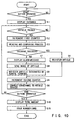
- the checkout process by the POS terminal 200 provided in the checkout lane is the same as the checkout process of the first embodiment in the process up to the step (S10) of displaying the total amount of articles on the sub-total display 36.
- the issuing machine 51 issues a number card having the number of the checkout lane, the number of the customer and the like magnetically recorded thereon (S15).
- each of the automatic settlement counters 53-1, 53-2 as shown in FIG. 11, if a number card is inserted into the settlement device 55, magnetic information recorded on the number card is read and an inquiry is made to the POS terminal 200 of the corresponding checkout lane to check whether the information is correct or not (S31). Next, if the information recorded on the number card is correct, the total amount for the corresponding customer is received from the POS terminal 200 of the corresponding checkout lane and displayed on the display 58.
- the settlement process that is, cash registration process is effected (S32).
- the process is effected by inserting a pre-paid card, credit card or cash into the automatic payment machine 56 according to the total amount for the articles displayed on the display 58 and effecting the payment process.
- a change is calculated and a change is given back from the change discharging port, if any.
- the cash register 60 of the cashier counter 54 reads magnetic information recorded on the number card and makes an inquiry to the POS terminal 200 of the corresponding checkout lane to check whether the information is correct or not (S41). Next, if the information recorded on the number card is correct, the total amount for the corresponding customer is received from the POS terminal 200 of the corresponding checkout lane and displayed on the displays 62, 63.
- the settlement process that is, cash registration process is effected (S42).
- the process is effected by the operation of the customer of recognizing the total amount and paying cash to the cashier 65 and the operation of the cashier 65 of inputting the amount of received cash by use of the keyboard 61.
- the customer 25 effects a sequence of article registration operations according to the following operation procedure.
- the operation procedure is the same as that of the first embodiment in the process effected until the customer 25 depresses the end button 34 after placing all of the articles 26 on the article placing area 27 and recognizes the total amount displayed on the sub-total display 36.
- the customer 25 recognizes the total amount displayed on the sub-total display 36 and receives a number card issued from the issuing machine 51. Then, the customer 25 puts the registered articles 26a carried to the article stacker 32 into the shopping basket 22 again and goes to the automatic settlement counter or cashier counter.
- the customer 25 goes to the automatic settlement counter 53-1, 53-2 for the settlement process, the customer inserts his number card. Then, since the total amount is displayed on the display 58, the customer 25 recognizes the to-be-paid total amount displayed on the display 58 and inserts a pre-paid card into the automatic payment machine 56.
- the automatic payment machine 56 terminates the settlement process if the remainder of the pre-paid card is equal to or larger than the total amount. If the remainder of the pre-paid card is smaller than the total amount, the automatic payment machine 56 displays the deficient amount of money on the sub-total display 58. Therefore, the customer 25 pays the deficient amount of money by cash to the automatic payment machine 56. In this case, a change is given, if any.
- the receipt issuing machine 57 issues a receipt.
- the gate 59 is released from the locked state.
- the customer 25 receives the receipt and passes through the gate 59.
- the gate 59 is closed again and locked.
- the customer 25 puts the articles in the shopping basket 22 into a bag and leaves the store.
- the customer 25 goes to the cashier counter 54, the customer hands his number card over to the cashier 65.
- the cashier 65 inserts the received number card into the insertion port of the cash register 60.
- the customer pays cash to the cashier 65 according to the to-be-paid amount displayed on the display 62.
- the cashier 65 inputs the amount of received cash by use of the keys on the keyboard 61. At this time, a change is displayed on the displays 62, 63, if any. Further, a receipt is issued from the receipt issuing machine 64.
- the cashier 65 hands the change and receipt over to the customer 25.
- the customer 25 receives the change and receipt, puts the articles in the shopping basket 22 into a bag and then leaves the store.
- the height measuring apparatus having two support poles on which a plurality of light emitting elements 103, --- and a plurality of light receiving elements 104, --- are arranged in opposite positions at a preset pitch is used, but this is not limitative.
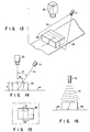
- a height measuring apparatus shown in FIG. 13 has a light source 71 for emitting slit light 70 in an oblique direction with respect to the article 26 and a video camera 30 to measure the height of the article by the light-section method. That is, as shown in FIG. 14, if the slit light 70 is inclined at a preset angle ⁇ with respect to the central axis of the video camera 30, the distance w between a line formed of the slit light 70 projected on the upper surface of the article 26 and a line formed of the slit light 70 projected on the belt conveyor 24 varies with the height of the article 26.
- the value of the distance w can be derived from a 2-dimensional image obtained by the video camera 30 and the height h of the article 26 can be calculated by use of the value of the distance w.
- the height of the article 26 can be measured but also the position and shape of the article 26 can be detected based on the 2-dimensional image of the slit light 70 by the height measuring apparatus shown in FIG. 13. Further, according to the height measuring apparatus, the height of the article 26 can be more precisely measured in comparison with the case of each of the embodiments, and therefore, the variable scanning optical systems 106, 107, 108 of the bar code scanner 31 can be more precisely adjusted. As a result, the reading process by the bar code scanner can be more stably effected. Further, it is possible to estimate a 3-dimensional image of the article carried by the belt conveyor 24 based on the 2-dimensional image of the slit light 70. Therefore, the article can be more reliably designated by use of a data base including the 3-dimensional image data.
- the height measuring apparatus includes an ultrasonic sensor head 73.
- An ultrasonic wave 74 is radiated from the ultrasonic sensor head 73 towards the belt conveyor 24 and the height of the article 26 is measured based on the phase difference between the radiated ultrasonic wave 74 and the ultrasonic wave reflected from the upper surface of the article 26.
- a height measuring apparatus in which a plurality of light emitting elements and a plurality of light receiving elements are arranged on one of two support poles and a reflection plate is disposed on the other support pole to face the light emitting elements may be used.
- the height of an article passing through between the two support poles is measured based on a variation in the light receiving condition of the light receiving elements which receive lights emitted from the light emitting elements and reflected from the reflection plate.
- the height of an article passing through between the two support poles may be measured by arranging the light receiving elements to receive reflected lights reflected from the article.
- the first and second counters 46 and 47 are provided in preset areas of the RAM 206 connected to the CPU 202.
- the content of the second counter 47 is cleared and the number of registered articles of a next customer is counted after the article registration for the preceding customer has been completed, there occurs a possibility that the article registration for the next customer is started before the article registration of the preceding customer is not yet completed, for example, and in such a case, it becomes impossible to use the second counter 47.
- the first and second counters 46 and 47 can be constructed by one up-down counter. That is, when the passage of the article is detected by means of the height measuring apparatus 29 and video camera 30, the content of the up-down counter is counted up, and when the article is registered by the reading/comparing process, the content of the up-down counter is counted down. When the content of the up-down counter is set to "0" after the end button 34 is depressed, the CPU 202 determines that the article registration for the customer is completed. In this case, by using an additional up-down counter, it becomes possible to cope with a case wherein the registration for a next customer is started before the registration for the preceding customer is completed.
- the belt conveyor is used as a carrying device for carrying articles, but this is not limitative.
- a pallet type carrying device or roller conveyor type carrying device can be used.
Landscapes
- Physics & Mathematics (AREA)
- General Physics & Mathematics (AREA)
- Cash Registers Or Receiving Machines (AREA)
- Management, Administration, Business Operations System, And Electronic Commerce (AREA)
Description
- a checkout lane comprising carrying means for carrying articles in one direction, image obtaining means for obtaining an image of an article carried by said carrying means, image processing means for extracting a feature of an article by processing the image of the article obtained by said image obtaining means, a height measuring means for measuring a height of an article carried by said carrying means, code reading means comprising a variable scanning optical system for optically reading an article code affixed to an article, said variable scanning optical system being adjusted based on the image of the article obtained by said image obtaining means and on the height of the article measured by said height measuring means, and article registering means for registering an article by decoding the article code read by said code reading means and, if the article code cannot be read, recognizing and registering an article based on the feature of the article extracted by said image processing means; and
- a remote terminal device comprising display means for displaying an image of an article which cannot be recognized by said article registering means and input means for accepting a designation of an article based on the image of the article displayed by said display means and disposed at a location away from said checkout lane;
- whereat said article registering means includes auxiliary registering means for registering an article designated by said remote terminal device.
Claims (9)
- A checkout system comprising:a checkout lane (21-1) comprising carrying means (24) for carrying articles in one direction, image obtaining means (30) for obtaining an image of an article carried by said carrying means, image processing means (202, 204, 206) for extracting a feature of an article by processing the image of the article obtained by said image obtaining means, a height measuring means (29) for measuring a height of an article carried by said carrying means (24), code reading means (31) comprising a variable scanning optical system (106, 107, 108) for optically reading an article code affixed to an article, said variable scanning optical system being adjusted based on the image of the article obtained by said image obtaining means and on the height of the article measured by said height measuring means, and article registering means (202, 204, 206) for registering an article by decoding the article code read by said code reading means, and if the article code cannot be read, recognizing and registering an article based on the feature of the article extracted by said image processing means; anda remote terminal device (41) comprising display means (43) for displaying an image of an article which cannot be recognized by said article registering means and input means (44) for accepting a designation of an article based on the image of the article displayed by said display means and disposed at a location away from said checkout lane;whereat said article registering means includes auxiliary registering means (202, 204, 206) for registering an article designated by said remote terminal device.
- A checkout system according to claim 1, characterized in that said checkout lane includes carriage control means (202, 204, 206) for temporarily stopping said carrying means (24), the image of an article obtained by said image obtaining means (30) is displayed on said display means (43) of said remote terminal device (41) and the carriage of the article by said carrying means (24) is temporarily interrupted by said carriage control means (202, 204, 206) when the article cannot be identified by said article registering means (202, 204, 206), and said carrying means (24) is driven again when the article is registered by use of designating means (44) based on the image of the displayed article.
- A checkout system according to claim 1, characterized in that said remote terminal device includes alarming means for informing that the article cannot be identified by said comparing means (202, 204, 206)
- A checkout system according to claim 1, characterized in that said checkout lane includes instruction inputting means (33, 34) for inputting start and end instruction of article registration, counting means (46, 47) for counting a number of articles which is conveyed into a predetermined area after the start instruction is input by said inputting means (33, 34) and a number of articles which have been registered, and completion detecting means (202, 204, 206) for detecting completion of article registration by confirming that the numbers of conveyed articles and registered articles counted by said counting means (46, 47) coincide with each other after the end instruction is input by said instruction inputting means (33, 34).
- A checkout system according to claim 1, characterized in that said checkout system includes settlement means (39) for effecting a settlement process based on the total amount for registered articles, and said settlement means (39) have gating means (40) for permitting articles to be carried out when the settlement process is completed.
- A checkout system according to claim 5, characterized in that said settlement means is disposed in said checkout lane (21-1).
- A checkout system according to claim 5, characterized in that said checkout lane includes card issuing means (52) for issuing a card on which customer number data and number data of the checkout lane (21-1) in which the article is registered are recorded and said settlement means (39) for displaying the total amount for registered articles and effecting the settlement process based on data recorded on the card is disposed in position apart from said checkout lane (21-1).
- A checkout system according to claim 5, characterized in that said settlement means includes sub-total display means (36) for displaying the total amount for registered articles, automatic payment means (37) for effecting the payment process based on the total amount displayed on said sub-total display means (36), and receipt issuing means (38) for issuing a receipt after the payment process by said automatic payment means (37) is completed.
- A checkout system according to claim 1, characterized in that said code reading means (31) is disposed on a downstream side of said image obtaining means (30) and said height measuring means (29), along a direction in which an article is carried.
Applications Claiming Priority (3)
| Application Number | Priority Date | Filing Date | Title |
|---|---|---|---|
| JP116841/94 | 1994-05-30 | ||
| JP11684194A JP3213669B2 (en) | 1994-05-30 | 1994-05-30 | Checkout system |
| JP11684194 | 1994-05-30 |
Publications (3)
| Publication Number | Publication Date |
|---|---|
| EP0689175A2 EP0689175A2 (en) | 1995-12-27 |
| EP0689175A3 EP0689175A3 (en) | 1999-07-07 |
| EP0689175B1 true EP0689175B1 (en) | 2003-05-02 |
Family
ID=14696958
Family Applications (1)
| Application Number | Title | Priority Date | Filing Date |
|---|---|---|---|
| EP95108210A Expired - Lifetime EP0689175B1 (en) | 1994-05-30 | 1995-05-30 | Check out system for identifying and registering articles |
Country Status (4)
| Country | Link |
|---|---|
| US (1) | US5609223A (en) |
| EP (1) | EP0689175B1 (en) |
| JP (1) | JP3213669B2 (en) |
| DE (1) | DE69530542T2 (en) |
Families Citing this family (120)
| Publication number | Priority date | Publication date | Assignee | Title |
|---|---|---|---|---|
| US5742038A (en) * | 1990-09-28 | 1998-04-21 | Symbol Technologies, Inc. | Beam shaping for optical scanners |
| CA2170934C (en) * | 1995-03-17 | 2007-06-19 | Paul Dvorkis | Optical scanners having dual surface optical elements for dual working ranges |
| US6069696A (en) * | 1995-06-08 | 2000-05-30 | Psc Scanning, Inc. | Object recognition system and method |
| EP0811958A3 (en) * | 1996-06-05 | 2004-09-29 | NCR International, Inc. | Self-service checkout apparatus and methods |
| US5969317A (en) * | 1996-11-13 | 1999-10-19 | Ncr Corporation | Price determination system and method using digitized gray-scale image recognition and price-lookup files |
| US5923017A (en) * | 1997-01-23 | 1999-07-13 | United Parcel Service Of America | Moving-light indicia reader system |
| US5920056A (en) * | 1997-01-23 | 1999-07-06 | United Parcel Service Of America, Inc. | Optically-guided indicia reader system for assisting in positioning a parcel on a conveyor |
| US5987426A (en) | 1997-10-14 | 1999-11-16 | Ncr Corporation | Point-of-sale system including isolation layer between client and server software |
| US6414713B1 (en) * | 1997-12-25 | 2002-07-02 | Casio Computer Co., Ltd. | Commodity image data processors, recording mediums which contain a commodity image data processing program, and image pickup aiding apparatus |
| US5967264A (en) | 1998-05-01 | 1999-10-19 | Ncr Corporation | Method of monitoring item shuffling in a post-scan area of a self-service checkout terminal |
| DE19906311C2 (en) * | 1999-02-16 | 2002-01-10 | Christian Siebert | Procedure for enacting customer activities in retail stores |
| US6286758B1 (en) | 1999-02-17 | 2001-09-11 | Ncr Corporation | Reconfigurable checkout system |
| US6856964B1 (en) | 1999-03-22 | 2005-02-15 | Ncr Corporation | System and methods for integrating a self-checkout system into an existing store system |
| JP3573652B2 (en) * | 1999-04-06 | 2004-10-06 | 松下電器産業株式会社 | Bagging error detection system |
| US6201473B1 (en) * | 1999-04-23 | 2001-03-13 | Sensormatic Electronics Corporation | Surveillance system for observing shopping carts |
| US6213395B1 (en) | 1999-11-02 | 2001-04-10 | Ncr Corporation | Apparatus and method for operating a checkout system having a scanner which is rotatable between an assisted scanner position and a self-service scanner position |
| US6296185B1 (en) | 1999-11-02 | 2001-10-02 | Ncr Corporation | Apparatus and method for operating a checkout system having a display monitor which displays both transaction information and customer-specific messages during a checkout transaction |
| US6409081B1 (en) | 1999-11-02 | 2002-06-25 | Ncr Corporation | Apparatus and method for operating a checkout system having an item set-aside shelf which is movable between a number of shelf positions |
| US6502749B1 (en) | 1999-11-02 | 2003-01-07 | Ncr Corporation | Apparatus and method for operating a checkout system having an RF transmitter for communicating to a number of wireless personal pagers |
| US6427915B1 (en) | 1999-11-02 | 2002-08-06 | Ncr Corporation | Method of operating checkout system having modular construction |
| US6296184B1 (en) | 1999-11-02 | 2001-10-02 | Ncr Corporation | Apparatus and method for operating a checkout system having a security scale for providing security during an assisted checkout transaction |
| US6354497B1 (en) | 1999-11-02 | 2002-03-12 | Ncr Corporation | Apparatus and method for operating a checkout system having a number of interface terminals associated therewith |
| US6540137B1 (en) | 1999-11-02 | 2003-04-01 | Ncr Corporation | Apparatus and method for operating a checkout system which has a number of payment devices for tendering payment during an assisted checkout transaction |
| US6427914B1 (en) | 1999-11-02 | 2002-08-06 | Ncr Corporation | Apparatus and method for operating a checkout system having a number of port expander devices associated therewith |
| US6343739B1 (en) | 1999-11-02 | 2002-02-05 | Ncr Corporation | Apparatus and method for operating a checkout system having a video camera for enhancing security during operation thereof |
| US6530520B1 (en) | 1999-11-02 | 2003-03-11 | Ncr Corporation | Apparatus and method for operating a checkout system having an RF transmitter for communicating to a receiver associated with an intercom system |
| US6390363B1 (en) | 1999-11-02 | 2002-05-21 | Ncr Corporation | Apparatus and method for operating convertible checkout system which has a customer side and a personnel side |
| US7255200B1 (en) * | 2000-01-06 | 2007-08-14 | Ncr Corporation | Apparatus and method for operating a self-service checkout terminal having a voice generating device associated therewith |
| US6446869B1 (en) * | 2000-02-10 | 2002-09-10 | Ncr Corporation | Ambient light blocking apparatus for a produce recognition system |
| US7954719B2 (en) * | 2000-11-24 | 2011-06-07 | Metrologic Instruments, Inc. | Tunnel-type digital imaging-based self-checkout system for use in retail point-of-sale environments |
| US7540424B2 (en) * | 2000-11-24 | 2009-06-02 | Metrologic Instruments, Inc. | Compact bar code symbol reading system employing a complex of coplanar illumination and imaging stations for omni-directional imaging of objects within a 3D imaging volume |
| US6598791B2 (en) * | 2001-01-19 | 2003-07-29 | Psc Scanning, Inc. | Self-checkout system and method including item buffer for item security verification |
| US20020112940A1 (en) * | 2001-02-16 | 2002-08-22 | Scott Dickover | Methods and apparatus for improved self-checkout system |
| US6588549B2 (en) | 2001-07-06 | 2003-07-08 | Ncr Corporation | Checkout system convertible between assisted and non-assisted configurations |
| NL1018512C1 (en) * | 2001-07-11 | 2001-11-02 | Beheermij Van Der Loo B V | Automatic cash register system. |
| NL1021040C2 (en) * | 2001-07-11 | 2004-01-27 | Beheermij Van Der Loo B V | Method is for handling purchased goods at automatic cashdesk check-out and involves prior storage in memory of information of a measurable parameter of articles to be handled |
| US6994252B2 (en) * | 2001-11-05 | 2006-02-07 | Frich Mark R | Combination library patron-supervisor self check-in/out workstation |
| EP1313069A1 (en) * | 2001-11-14 | 2003-05-21 | Sys S.p.A.. | System for label authenticity check and certifying, and multiple access database used in this system |
| EP1479054B1 (en) * | 2002-02-01 | 2012-05-02 | Datalogic Adc, Inc. | Combined data reader and electronic article surveillance (eas) system |
| US7527198B2 (en) | 2002-03-18 | 2009-05-05 | Datalogic Scanning, Inc. | Operation monitoring and enhanced host communications in systems employing electronic article surveillance and RFID tags |
| US7248754B2 (en) * | 2003-05-05 | 2007-07-24 | International Business Machines Corporation | Apparatus and method for determining whether machine readable information on an item matches the item |
| US7118026B2 (en) * | 2003-06-26 | 2006-10-10 | International Business Machines Corporation | Apparatus, method, and system for positively identifying an item |
| DE20312065U1 (en) * | 2003-08-05 | 2004-12-23 | Wincor Nixdorf International Gmbh | Detection device for objects provided with machine-readable data |
| TWI245227B (en) * | 2004-02-13 | 2005-12-11 | Hon Hai Prec Ind Co Ltd | System and method for automatically scanning bar code symbols |
| US7246745B2 (en) | 2004-02-27 | 2007-07-24 | Evolution Robotics Retail, Inc. | Method of merchandising for checkout lanes |
| US7337960B2 (en) | 2004-02-27 | 2008-03-04 | Evolution Robotics, Inc. | Systems and methods for merchandise automatic checkout |
| US7100824B2 (en) * | 2004-02-27 | 2006-09-05 | Evolution Robotics, Inc. | System and methods for merchandise checkout |
| US7316354B2 (en) * | 2004-03-11 | 2008-01-08 | Vocollect, Inc. | Method and system for voice enabling an automated storage system |
| US7416118B2 (en) * | 2004-05-14 | 2008-08-26 | Digital Site Management, Llc | Point-of-sale transaction recording system |
| US7516888B1 (en) * | 2004-06-21 | 2009-04-14 | Stoplift, Inc. | Method and apparatus for auditing transaction activity in retail and other environments using visual recognition |
| US7631808B2 (en) * | 2004-06-21 | 2009-12-15 | Stoplift, Inc. | Method and apparatus for detecting suspicious activity using video analysis |
| US8448858B1 (en) * | 2004-06-21 | 2013-05-28 | Stoplift, Inc. | Method and apparatus for detecting suspicious activity using video analysis from alternative camera viewpoint |
| US7071452B2 (en) * | 2004-10-28 | 2006-07-04 | Tri-Tronics Company, Inc. | Self-calibrating photoelectric control system |
| US7963448B2 (en) * | 2004-12-22 | 2011-06-21 | Cognex Technology And Investment Corporation | Hand held machine vision method and apparatus |
| US7619527B2 (en) | 2005-02-08 | 2009-11-17 | Datalogic Scanning, Inc. | Integrated data reader and electronic article surveillance (EAS) system |
| JP2006350806A (en) * | 2005-06-17 | 2006-12-28 | Toshiba Tec Corp | Wireless tag recognition device and product sales data processing device |
| US7222785B2 (en) * | 2005-08-16 | 2007-05-29 | Toshiba Tec Kabushiki Kaisha | Commodity information registering apparatus and commodity information registering method |
| JP2007206996A (en) * | 2006-02-02 | 2007-08-16 | Nippon Signal Co Ltd:The | Barcode reader and self-checkout register system using the same |
| JP4796863B2 (en) * | 2006-02-21 | 2011-10-19 | 東芝テック株式会社 | Product sales data processing device |
| US20080061139A1 (en) * | 2006-09-07 | 2008-03-13 | Ncr Corporation | Self-checkout terminal including scale with remote reset |
| US7422147B2 (en) * | 2006-12-22 | 2008-09-09 | Walter Steven Rosenbaum | System and method for detecting fraudulent transactions of items having item-identifying indicia |
| US7612302B2 (en) * | 2007-04-04 | 2009-11-03 | Mettler-Toledo, Inc. | System and method for alerting an operator |
| US7988045B2 (en) * | 2007-05-31 | 2011-08-02 | International Business Machines Corporation | Portable device-based shopping checkout |
| US8794524B2 (en) * | 2007-05-31 | 2014-08-05 | Toshiba Global Commerce Solutions Holdings Corporation | Smart scanning system |
| GB2451073A (en) * | 2007-07-16 | 2009-01-21 | Hawk Surveillance Systems Ltd | Checkout surveillance system |
| US20090026270A1 (en) * | 2007-07-24 | 2009-01-29 | Connell Ii Jonathan H | Secure checkout system |
| US8544736B2 (en) | 2007-07-24 | 2013-10-01 | International Business Machines Corporation | Item scanning system |
| US7909248B1 (en) * | 2007-08-17 | 2011-03-22 | Evolution Robotics Retail, Inc. | Self checkout with visual recognition |
| US8068674B2 (en) | 2007-09-04 | 2011-11-29 | Evolution Robotics Retail, Inc. | UPC substitution fraud prevention |
| WO2009070696A1 (en) * | 2007-11-26 | 2009-06-04 | Proiam, Llc | Enrollment apparatus, system, and method |
| US7677451B2 (en) * | 2007-12-20 | 2010-03-16 | International Business Machines Corporation | Reducing incident infrared radiation received by one or more infrared detectors in a self checkout point of sale system |
| US8746557B2 (en) | 2008-02-26 | 2014-06-10 | Toshiba Global Commerce Solutions Holding Corporation | Secure self-checkout |
| US8280763B2 (en) * | 2008-02-26 | 2012-10-02 | Connell Ii Jonathan H | Customer rewarding |
| US8061603B2 (en) * | 2008-03-20 | 2011-11-22 | International Business Machines Corporation | Controlling shopper checkout throughput |
| US7889068B2 (en) * | 2008-03-20 | 2011-02-15 | International Business Machines Corporation | Alarm solution for securing shopping checkout |
| US8229158B2 (en) * | 2008-04-29 | 2012-07-24 | International Business Machines Corporation | Method, system, and program product for determining a state of a shopping receptacle |
| US20090272801A1 (en) * | 2008-04-30 | 2009-11-05 | Connell Ii Jonathan H | Deterring checkout fraud |
| US7448542B1 (en) | 2008-05-05 | 2008-11-11 | International Business Machines Corporation | Method for detecting a non-scan at a retail checkout station |
| US20100053329A1 (en) * | 2008-08-27 | 2010-03-04 | Flickner Myron D | Exit security |
| DE102008044795A1 (en) * | 2008-08-28 | 2010-03-04 | Wincor Nixdorf International Gmbh | Goods acquisition at self-service checkout systems |
| US8704821B2 (en) * | 2008-09-18 | 2014-04-22 | International Business Machines Corporation | System and method for managing virtual world environments based upon existing physical environments |
| US9299229B2 (en) * | 2008-10-31 | 2016-03-29 | Toshiba Global Commerce Solutions Holdings Corporation | Detecting primitive events at checkout |
| US8253831B2 (en) * | 2008-11-29 | 2012-08-28 | International Business Machines Corporation | Location-aware event detection |
| US8571298B2 (en) | 2008-12-23 | 2013-10-29 | Datalogic ADC, Inc. | Method and apparatus for identifying and tallying objects |
| US9047742B2 (en) * | 2009-05-07 | 2015-06-02 | International Business Machines Corporation | Visual security for point of sale terminals |
| DE102009044156B4 (en) * | 2009-10-01 | 2022-01-20 | Wincor Nixdorf International Gmbh | System for a self-service goods registration station and method therefor |
| JP4997321B2 (en) * | 2010-07-01 | 2012-08-08 | 東芝テック株式会社 | Code reader and program |
| JP2012053710A (en) * | 2010-09-01 | 2012-03-15 | Toshiba Tec Corp | Store system, sales registration device and program |
| DE102011000087A1 (en) * | 2011-01-11 | 2012-07-12 | Wincor Nixdorf International Gmbh | Transport unit and method for operating the same |
| US8657196B2 (en) | 2011-01-24 | 2014-02-25 | Datalogic ADC, Inc. | Systems and methods of capturing security images in an automated data reader |
| USD668656S1 (en) * | 2011-01-24 | 2012-10-09 | Datalogic ADC, Inc. | Tunnel scanner |
| US8556084B1 (en) | 2011-04-29 | 2013-10-15 | American Airlines, Inc. | Baggage cart handling system |
| US8336761B1 (en) * | 2011-09-15 | 2012-12-25 | Honeywell International, Inc. | Barcode verification |
| DE102012101267A1 (en) * | 2012-02-17 | 2013-08-22 | Wincor Nixdorf International Gmbh | POS system arrangement |
| US20150095189A1 (en) * | 2012-03-16 | 2015-04-02 | In Situ Media Corporation | System and method for scanning, tracking and collating customer shopping selections |
| JP5553866B2 (en) * | 2012-07-23 | 2014-07-16 | 東芝テック株式会社 | Product recognition device and recognition dictionary addition program |
| US9651363B2 (en) | 2012-07-24 | 2017-05-16 | Datalogic Usa, Inc. | Systems and methods of object measurement in an automated data reader |
| US20150242833A1 (en) * | 2012-08-03 | 2015-08-27 | Nec Corporation | Information processing device and screen setting method |
| JP5936993B2 (en) * | 2012-11-08 | 2016-06-22 | 東芝テック株式会社 | Product recognition apparatus and product recognition program |
| JP2014174569A (en) * | 2013-03-05 | 2014-09-22 | Toshiba Tec Corp | Information processor and program |
| US20170185985A1 (en) * | 2014-03-28 | 2017-06-29 | Nec Corporation | Sales registration apparatus, program, and sales registration method |
| JP6008405B2 (en) * | 2014-04-16 | 2016-10-19 | Necプラットフォームズ株式会社 | Self-POS device and operation method thereof |
| JP5896489B2 (en) * | 2014-04-16 | 2016-03-30 | Necプラットフォームズ株式会社 | Self-POS device and operation method thereof |
| JP5753929B2 (en) * | 2014-05-27 | 2015-07-22 | 東芝テック株式会社 | Product recognition apparatus, method, and recognition dictionary addition program |
| JP6311590B2 (en) * | 2014-12-10 | 2018-04-18 | カシオ計算機株式会社 | Product processing system and product processing method |
| JP2016166089A (en) * | 2015-03-10 | 2016-09-15 | パナソニックIpマネジメント株式会社 | Article management apparatus and article management method |
| CA2940356A1 (en) * | 2015-09-28 | 2017-03-28 | Wal-Mart Stores, Inc. | Systems and methods of object identification and database creation |
| JP6608977B2 (en) * | 2018-01-25 | 2019-11-20 | ファナック株式会社 | Article transport system |
| JP6981538B2 (en) * | 2018-03-29 | 2021-12-15 | 日本電気株式会社 | Image identification cash register device, image identification cash register system, product information display method, and program |
| JP6569762B2 (en) * | 2018-04-03 | 2019-09-04 | 日本電気株式会社 | POS terminal device, POS system, image processing method and program |
| JP7218984B2 (en) * | 2018-04-27 | 2023-02-07 | 日本電気株式会社 | Product registration device, product registration method and program |
| US10867186B2 (en) | 2018-05-15 | 2020-12-15 | Genetec Inc. | Transaction monitoring |
| JP7030613B2 (en) * | 2018-05-25 | 2022-03-07 | 東芝テック株式会社 | Accounting equipment and its programs |
| WO2021101159A1 (en) * | 2019-11-22 | 2021-05-27 | 한화테크윈 주식회사 | Automatic payment apparatus |
| US11941604B2 (en) | 2018-12-17 | 2024-03-26 | Hanwha Vision Co., Ltd. | Automatic payment system |
| JP7053049B2 (en) * | 2019-10-30 | 2022-04-12 | 株式会社寺岡精工 | System, registration device and program |
| JP7419812B2 (en) * | 2019-12-27 | 2024-01-23 | 日本電気株式会社 | Accounting machines, accounting methods, and recording media |
| BR112022014347A2 (en) | 2020-01-21 | 2022-10-04 | Versa | SYSTEM FOR LOADING AND UNLOADING MONITORING OR TRANSFER OF GOODS AREA |
| GB2596330A (en) * | 2020-06-25 | 2021-12-29 | Tj Morris Ltd | Detection of under-scanning at a point of sale |
| US11288652B1 (en) * | 2020-10-30 | 2022-03-29 | Toshiba Global Commerce Solutions Holdings Corporation | Radio-frequency-identification-based checkout process |
Citations (3)
| Publication number | Priority date | Publication date | Assignee | Title |
|---|---|---|---|---|
| GB2161631A (en) * | 1984-07-09 | 1986-01-15 | Checkrobot Inc | System for security processing of retailed articles |
| US4920255A (en) * | 1988-10-31 | 1990-04-24 | Stephen C. Gabeler | Automatic incremental focusing scanner system |
| EP0491348A2 (en) * | 1990-12-17 | 1992-06-24 | Mika Mannerjoki | Unstaffed checkout system |
Family Cites Families (16)
| Publication number | Priority date | Publication date | Assignee | Title |
|---|---|---|---|---|
| CH504907A (en) * | 1969-03-26 | 1971-03-31 | Zellweger Uster Ag | Method and device for the identification of objects and application of the method to the issue of objects from warehouses |
| US4676343A (en) * | 1984-07-09 | 1987-06-30 | Checkrobot Inc. | Self-service distribution system |
| US4939355A (en) * | 1988-01-22 | 1990-07-03 | Spectra-Physics, Inc. | Automatic package label scanner |
| GB2217887B (en) * | 1988-04-22 | 1992-03-18 | Checkrobot Inc | A system for operator-unattended checkout of bulk and other articles |
| DE3813725A1 (en) * | 1988-04-22 | 1989-11-09 | Nixdorf Computer Ag | METHOD FOR THE OPTICAL SCANING OF MARKINGS ON OBJECTS AND DEVICE FOR ITS IMPLEMENTATION |
| US5010242A (en) * | 1989-05-08 | 1991-04-23 | Mars Incorporated | Method and apparatus for variable speed scanning of bar codes |
| US5019694A (en) * | 1989-09-29 | 1991-05-28 | Ncr Corporation | Overhead scanning terminal |
| DE4005105A1 (en) * | 1990-02-17 | 1991-08-22 | Werner Potrafke Spezialfabrik | CHECKOUT WITH SELF-SCANNING |
| DE4005081A1 (en) * | 1990-02-17 | 1991-08-22 | Torres Peraza Mario | SCALE, ESPECIALLY SELF-SERVICE SCALE |
| US5178234A (en) * | 1990-03-15 | 1993-01-12 | Tokyo Electric Co., Ltd. | Checkout apparatus |
| JPH0467291A (en) * | 1990-07-09 | 1992-03-03 | Tokyo Electric Co Ltd | checkout device |
| US5083638A (en) * | 1990-09-18 | 1992-01-28 | Howard Schneider | Automated point-of-sale machine |
| US5115888A (en) * | 1991-02-04 | 1992-05-26 | Howard Schneider | Self-serve checkout system |
| US5386107A (en) * | 1991-12-23 | 1995-01-31 | Symbol Technologies, Inc. | Scanning arrangement and method in which the focus is varied in operative correlation with the scanning angle |
| US5426282A (en) * | 1993-08-05 | 1995-06-20 | Humble; David R. | System for self-checkout of bulk produce items |
| US5497314A (en) * | 1994-03-07 | 1996-03-05 | Novak; Jeffrey M. | Automated apparatus and method for object recognition at checkout counters |
-
1994
- 1994-05-30 JP JP11684194A patent/JP3213669B2/en not_active Expired - Lifetime
-
1995
- 1995-05-30 DE DE69530542T patent/DE69530542T2/en not_active Expired - Fee Related
- 1995-05-30 US US08/451,278 patent/US5609223A/en not_active Expired - Lifetime
- 1995-05-30 EP EP95108210A patent/EP0689175B1/en not_active Expired - Lifetime
Patent Citations (3)
| Publication number | Priority date | Publication date | Assignee | Title |
|---|---|---|---|---|
| GB2161631A (en) * | 1984-07-09 | 1986-01-15 | Checkrobot Inc | System for security processing of retailed articles |
| US4920255A (en) * | 1988-10-31 | 1990-04-24 | Stephen C. Gabeler | Automatic incremental focusing scanner system |
| EP0491348A2 (en) * | 1990-12-17 | 1992-06-24 | Mika Mannerjoki | Unstaffed checkout system |
Also Published As
| Publication number | Publication date |
|---|---|
| JPH07320164A (en) | 1995-12-08 |
| DE69530542D1 (en) | 2003-06-05 |
| US5609223A (en) | 1997-03-11 |
| DE69530542T2 (en) | 2003-12-04 |
| JP3213669B2 (en) | 2001-10-02 |
| EP0689175A3 (en) | 1999-07-07 |
| EP0689175A2 (en) | 1995-12-27 |
Similar Documents
| Publication | Publication Date | Title |
|---|---|---|
| EP0689175B1 (en) | Check out system for identifying and registering articles | |
| EP0689174B1 (en) | Check out device for identifying and registering articles | |
| EP0689173B1 (en) | Self-scanning checkout apparatus having article passage detecting sensor | |
| US4676343A (en) | Self-service distribution system | |
| JP4874166B2 (en) | Checkout terminal | |
| US20040199427A1 (en) | Automatic check-out system | |
| CA1247241A (en) | System for security processing of retailed articles | |
| EP0375248A1 (en) | Method and apparatus for use in self-service shopping | |
| JPH03150686A (en) | Overhead scanning terminal | |
| KR101807205B1 (en) | Unattended payment device, Method for controlling the device, computer program for executing the method, and Apparatus for controlling the device | |
| KR20130139853A (en) | A checkout counter | |
| US20060180662A1 (en) | Check-out system | |
| JPH1074287A (en) | Pos system | |
| US5316107A (en) | Device for checking out goods | |
| KR101970003B1 (en) | Unattended store system, method for controlling the system, computer program for executing the method, and unattended payment device | |
| KR101793224B1 (en) | Unattended payment device, Method for controlling the device, computer program for executing the method, and Apparatus for controlling the device | |
| US20190272519A1 (en) | Sales data processing apparatus and sales data processing method | |
| JP2019139583A (en) | Settlement system | |
| JPH06231364A (en) | Automatic register system | |
| JPH1021323A (en) | Bar code reader | |
| JP4532636B2 (en) | Self-checkout system for product sales | |
| JP2744544B2 (en) | Product sales registration device | |
| JP2535495B2 (en) | Checkout device | |
| AU2002315954A1 (en) | Automatic check-out system | |
| KR20250164621A (en) | Information processing device, guidance system and program |
Legal Events
| Date | Code | Title | Description |
|---|---|---|---|
| PUAI | Public reference made under article 153(3) epc to a published international application that has entered the european phase |
Free format text: ORIGINAL CODE: 0009012 |
|
| AK | Designated contracting states |
Kind code of ref document: A2 Designated state(s): DE FR GB |
|
| PUAL | Search report despatched |
Free format text: ORIGINAL CODE: 0009013 |
|
| RAP1 | Party data changed (applicant data changed or rights of an application transferred) |
Owner name: TOSHIBA TEC KABUSHIKI KAISHA |
|
| AK | Designated contracting states |
Kind code of ref document: A3 Designated state(s): DE FR GB |
|
| 17P | Request for examination filed |
Effective date: 19990907 |
|
| 17Q | First examination report despatched |
Effective date: 20010508 |
|
| GRAH | Despatch of communication of intention to grant a patent |
Free format text: ORIGINAL CODE: EPIDOS IGRA |
|
| RTI1 | Title (correction) |
Free format text: CHECK OUT SYSTEM FOR IDENTIFYING AND REGISTERING ARTICLES |
|
| GRAH | Despatch of communication of intention to grant a patent |
Free format text: ORIGINAL CODE: EPIDOS IGRA |
|
| GRAA | (expected) grant |
Free format text: ORIGINAL CODE: 0009210 |
|
| AK | Designated contracting states |
Designated state(s): DE FR GB |
|
| REG | Reference to a national code |
Ref country code: GB Ref legal event code: FG4D |
|
| REF | Corresponds to: |
Ref document number: 69530542 Country of ref document: DE Date of ref document: 20030605 Kind code of ref document: P |
|
| ET | Fr: translation filed | ||
| PLBE | No opposition filed within time limit |
Free format text: ORIGINAL CODE: 0009261 |
|
| STAA | Information on the status of an ep patent application or granted ep patent |
Free format text: STATUS: NO OPPOSITION FILED WITHIN TIME LIMIT |
|
| 26N | No opposition filed |
Effective date: 20040203 |
|
| PGFP | Annual fee paid to national office [announced via postgrant information from national office to epo] |
Ref country code: DE Payment date: 20080605 Year of fee payment: 14 |
|
| PGFP | Annual fee paid to national office [announced via postgrant information from national office to epo] |
Ref country code: GB Payment date: 20080604 Year of fee payment: 14 |
|
| GBPC | Gb: european patent ceased through non-payment of renewal fee |
Effective date: 20090530 |
|
| REG | Reference to a national code |
Ref country code: FR Ref legal event code: ST Effective date: 20100129 |
|
| PG25 | Lapsed in a contracting state [announced via postgrant information from national office to epo] |
Ref country code: FR Free format text: LAPSE BECAUSE OF NON-PAYMENT OF DUE FEES Effective date: 20090602 |
|
| PGFP | Annual fee paid to national office [announced via postgrant information from national office to epo] |
Ref country code: FR Payment date: 20080514 Year of fee payment: 14 |
|
| PG25 | Lapsed in a contracting state [announced via postgrant information from national office to epo] |
Ref country code: GB Free format text: LAPSE BECAUSE OF NON-PAYMENT OF DUE FEES Effective date: 20090530 |
|
| PG25 | Lapsed in a contracting state [announced via postgrant information from national office to epo] |
Ref country code: DE Free format text: LAPSE BECAUSE OF NON-PAYMENT OF DUE FEES Effective date: 20091201 |