EP0688498A2 - A milking plant - Google Patents
A milking plant Download PDFInfo
- Publication number
- EP0688498A2 EP0688498A2 EP95202054A EP95202054A EP0688498A2 EP 0688498 A2 EP0688498 A2 EP 0688498A2 EP 95202054 A EP95202054 A EP 95202054A EP 95202054 A EP95202054 A EP 95202054A EP 0688498 A2 EP0688498 A2 EP 0688498A2
- Authority
- EP
- European Patent Office
- Prior art keywords
- sensor arrangement
- milking
- milking plant
- cleaning
- window
- Prior art date
- Legal status (The legal status is an assumption and is not a legal conclusion. Google has not performed a legal analysis and makes no representation as to the accuracy of the status listed.)
- Granted
Links
Images


Classifications
-
- A—HUMAN NECESSITIES
- A01—AGRICULTURE; FORESTRY; ANIMAL HUSBANDRY; HUNTING; TRAPPING; FISHING
- A01J—MANUFACTURE OF DAIRY PRODUCTS
- A01J5/00—Milking machines or devices
- A01J5/017—Automatic attaching or detaching of clusters
- A01J5/0175—Attaching of clusters
-
- G—PHYSICS
- G01—MEASURING; TESTING
- G01S—RADIO DIRECTION-FINDING; RADIO NAVIGATION; DETERMINING DISTANCE OR VELOCITY BY USE OF RADIO WAVES; LOCATING OR PRESENCE-DETECTING BY USE OF THE REFLECTION OR RERADIATION OF RADIO WAVES; ANALOGOUS ARRANGEMENTS USING OTHER WAVES
- G01S7/00—Details of systems according to groups G01S13/00, G01S15/00, G01S17/00
- G01S7/48—Details of systems according to groups G01S13/00, G01S15/00, G01S17/00 of systems according to group G01S17/00
- G01S7/481—Constructional features, e.g. arrangements of optical elements
- G01S7/4811—Constructional features, e.g. arrangements of optical elements common to transmitter and receiver
- G01S7/4813—Housing arrangements
Definitions
- the invention relates to milking plants as described in the preamble of claim 1 following the present description.
- Such a milking plant is known from e.g. the non-prepublished European Patent Application 89202372.2.
- a sensor utilizing light radiation is present for determining the position of the teats of an animal, so as to enable an automatic application of teat cups thereto.
- Light sensors including laser sensors, are generally known for the purpose of successive tracking or locating of objects. When applied in a milking robot, however, the functioning of the robot appears to be not as consistent as may be expected, particularly in that the teats of an animal are not always, or at least insufficiently accurately, found.
- a milking plant for automatically milking animals and for automatically applying teat cups thereof, utilizing a light sensor for determining the exact position of the teats of an animal to be milked may be improved by a construction as described in the characterizing part of the said claim 1.
- the malfunctioning of the known milking plant is due to the light sensor arrangement thereof, more specifically to exterior circumstances influencing its functioning. Cleaning of the translucent parts of the light sensor arrangement appeared to improve the functioning of the milking plant.
- the particular construction according to the invention has the advantage of a reduced maintenance of the milking plant and of a further relief of the necessary operating tasks for the farmer.
- the sensor arrangement of the milking plant is capable of performing a test for checking the cleanliness of its translucent parts. This has the advantage that an indication of the necessity of cleaning the sensor arrangement may be achieved automatically, so that the independency of the operation of the milking plant may be enhanced considerably. In this way, the farmer is also relieved from regularly checking the cleanliness of the sensor arrangement.
- the automatic cleaning of the sensor arrangement is effected when, after testing of the cleanliness of the sensor arrangement, it is found to be insufficient.
- the cleaning means comprise a sponge, while means are present for applying a cleaning liquid to the cleaning means.
- the light sensor arrangement is located on the robot arm.
- the sensor arrangement is constantly brought close to the teats of the animal after the robot arm is positioned roughly in the neighbourhood thereof.
- the finding of the exact position of a teat by the light sensor is thus made easier in that the sensor is brought close to the teat and in a favourable position for the undisturbed radiation of light.
- This construction is also favourable in that the arm carrying the sensor simultaneously carries the teat cup to be connected to the teat to be located, thus realizing a quick and efficient application of teat cups and an economic construction of the robotic part of the milking plant.
- the light sensor arrangement is located on the teat cup carrying end portion of the robot arm.
- the above-described automatic cleaning of the sensor arrangement appears to be particularly useful in the latter embodiment in that, apart from contamination by splashes of animal excrements, the arrangement in this construction also gets contaminated by pre-releases of milk occurring at certain cows and by dirt on the animal's udder. Although the teats and the lower part of the udder are normally cleaned before milking, they may still be moist or partially wet and thus appear to be a source by which the sensor arrangement on the end of a robot arm may get smudged.
- means are present for cleaning the sensor arrangement through a sliding movement over the translucent parts of the sensor arrangement.
- the activating means such as pressurized air or liquid
- testing means for testing the light sensor arrangement are provided at a known distance from the light sensor arrangement, when the latter is in a testing position.
- Figure 1 shows an arrangement for determining the distance therefrom to an object in accordance with the invention
- the arrangement 1 measures the distance to the object A and comprises a housing 2, a window 3, a reflecting element 4, a transmitter element 5 and a receiver element 6.
- the reflecting element 4 includes the reflector 7 for reflecting the radiation 8 originating from the transmitter element 5 and the reflector 9 for reflecting the radiation 10 reflected from the object.
- the transmitter element 5 transmits via the reflector 7 through the window 3 light rays to the object 2, where the radiation is reflected and dispersed. Part of this reflected and dispersed radiation returns to the housing again via the window 3 and is directed to the receiver element 6 by the reflector 9.
- the transmitted radiation beam is reflected horizontally.
- the reflectors 7 and 9 of the reflector element 4 are arranged at an angle B.
- the angle B it is achieved that the radiation beams 8 and 10 remain separated from each other.
- the angle B is also such that the radiation beams cannot reach the inner wall 13 of the housing.
- the separation of the beams is possible in the first instance by arranging the reflectors 7 and 9 at different heights and, with respect to the window 3, one behind the other. These conditions yield four possible configurations, two of which are shown in Figures 1 and 2. These Figures show the configurations wherein the reflector 7 for the transmitted radiation beam is disposed above the reflector 9 for the received radiation beam.
- this configuration is preferred to that wherein the reflector 9 for the received beam is located above the reflector 7. More specifically, this is the case when the arrangement is limited in its vertical movement by e.g. a ceiling or a similar obstacle. Since the transmitted radiation beam 8 is reflected and slightly dispersed by the object as diffuse light 14, it is irrelevant whether the reflector for the received radiation beam is located above, beside or below the reflector 7 of the transmitted radiation beam. Consequently, the configurations of Figures 1 and 2 render it possible for the arrangement to be located very closely to a ceiling, while measurements by means of a horizontally reflected transmitted radiation beam remain possible.
- FIG. 2 shows a further improvement of the reflector arrangement.
- the reflector 7 for the transmitted radiation beam 8 is located, relative to the window 3, behind the reflector 9. Since also the transmitter element 5 is located, with respect to the window 3, behind the receiver element 6, this configuration effects that the transmitted radiation beam 8 does not intersect the incident received radiation beam 10, so that no dispersion occurs.
- An optimum signal reception is effected not only by separating the radiation beams 8, 10, but also by inter alia counteracting dispersions and reflections inside the housing and by limiting incident ambient light.
- the transmitted radiation beam 8 and the received radiation beam 10 are separated from each other by means of a separator element 11. This element is opaque.
- the quantity of dispersed light which e.g. is produced by incident ambient light coming into contact with the transmitted radiation beam, is reduced still further.
- the receiver element 6 and the transmitter element 5 are fitted closely below the reflector element 4.
- the carrier elements 12 are clamped with a tight fit in the relevant space.
- a space 15 which is suitable for the accommodation of at least the control electronics 16 of the transmitter and receiver elements.
- the transmitter and the receiver elements bear on the bottom 17 of the housing and the control electronics is installed outside the housing.
- the counteracting of reflections is effected inter alia by the provision of relief elements.
- the relief elements may consist of bulges 18 which, as shown in the embodiment of Figure 1, are arranged at an interspace of 30 mms along the entire circumference of the wall 13 and transversely to the direction of the radiation beams 8, 10.
- an advantageous relief structure is also obtained by applying spherical bulges or recesses 19, as is shown schematically in Figure 3.
- the counteracting of incident ambient light is effected by reducing the dimensions of the window 3 to an aperture size required for the ingoing and outgoing radiation beams 8 and 10, respectively.
- Figure 4 clearly illustrates that, for that purpose, the window 3 is divided into two portions: i.e. a window portion 21 for the outgoing radiation beam 8 and a window portion 22 for the light reflected from and dispersed by the object.
- the window of the arrangement may be in the form of an aperture.
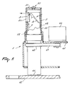
- Figures 6 and 7 show an embodiment of the arrangement 1 having a sealed window 23.
- This sealing may consist of glass or a translucent synthetic resin material. So as to prevent the occurrence of reflections because of the sealed window 23, in the embodiment of Figure 1 the inner side of the sealed window 23 is coated with an anti- reflection layer.
- a further measure to prevent reflections can be obtained by making the housing or, in case of the embodiment in Figure 2, the housing of only the receiver element of semi-transparent material. The light incident on the inner wall 13 is then allowed to pass, whilst light from the outside cannot enter.
- the sealing of the window 3 prevents the penetration of dirt into the housing.
- a disadvantage is that the cover itself may get dirty, which might disadvantageously affect the distance measurement.
- a special means 25 which covers the window during the major portion of the time. This cover is only removed when a measuring operation is actually being performed with the arrangement. This cover means can also be used with a non-sealed window.
- the cover plate 26 is suspended from a parallelogram construction formed by the arms 27 and 28.
- the hinging pins 29 are connected rigidly to the housing 2.
- the hinging pins 30 connect the parallelogram arms 27 and 28 to the cover plate 26.
- the parallelogram arm 27 is extended such as to be capable of acting as a lever.
- the arm 27 is moved by means of a cylinder 31 which bears against the housing itself, i.e. via a support 32, to which the cylinder 31 is connected via a hinge pin 33.
- the lifting cylinder 31 can be moved by means of both air and liquid.
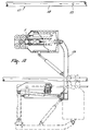
- the parallelogram construction is replaced by a sealing ring 34 which envelops the housing and is slidable along the housing by means of a lifting cylinder 31. During this sliding movement, the sealing ring is guided by the guide members 35 ( Figure 8).
- the guide members may be in the form of bearings, self-lubricating synthetic resin materials or a modern plastics material having a low coefficient of sliding resistance.
- the two embodiments of the cover means 25 can be equipped with means for automatic cleaning the window.
- the cover plate portion present in front of the window is fitted with a sponge 36.
- This sponge can be wetted with a cleaning agent via a supply line 37 to terminate in the injection point 38.
- this injection point is located at the upper side of the sponge, but different positions are alternatively possible. It is also conceivable for the cleaning agent supply line 37 to be branched into various injection points.
- the arrangement is in the form of a tube, as is shown in the embodiments of Figure 1 and 2.
- the arrangement 1 is maintained in position by a holder 41 and a carrier 42.
- this housing is bearing-supported relative to the holder 41 and the carrier 42 by means of a sliding member 43 and the bearing elements 44, respectively.
- the sliding member 43 may be designed as a bearing, a self-lubricating ring or a ring made of a modern plastics material having a low coefficient of sliding resistance.
- the housing 2 as is shown in Figure 9 can be put into movement by means of a motor 46 and an endless element 47 to engage a drive means 48 at the housing 2.
- This drive means 48 is an annular ridge having a flat side or a welded annular element having a flat side, around which the endless element 47, in particular a belt, can be passed.
- the drive means 48 may alternatively be designed as a cam disc, the endless element 47 then including a profiled belt or chain to engage the cam disc.
- Figure 9 shows an embodiment of the arrangement 1 wherein the housing 2 is assembled from an inner housing 49 and an outer housing 50.
- the inner housing 49 is rotatable about the common axis of the two housings.
- the axis of rotation extends through the centring point 51 in the upper ends of the two housings.
- Both the upper end of the inner housing and the upper end of the outer housing completely seal the relevant housing at its upper side.
- the outer housing 50 has a window 54.
- the inner housing 49 is reciprocated by the motor with the aid of a drive element.
- a limited area is checked for the presence of an object A.
- a region of more than 120° is covered in a horizontal plane.
- the window 54 thereof covers a much wider peripheral plane than the window of the inner housing 49. In the embodiment of Figure 9, this range is approximately 120° with a uniform distribution thereof on either side of the centre of the inner window, when the inner housing is in its starting position.
- the structure comprising two housings provides additional possibilities as regards the cleaning of the arrangement.
- this reduces the risk of dirt penetrating into the housing and/or, when the inner window is covered, contamination of this inner window.
- the window in the outer housing 50 is sealed, these problems do not occur for the inner window.
- the outer housing is provided near its lower side with flushing holes 55, through which dirt can be removed with the aid of air or water.
- An other solution to this problem may be provided by the use of gasket rings located between the two housings and immediately below the window apertures.
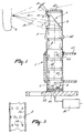
- a specific use of the arrangement 1 is obtained when it is employed to determine the position of the teats of a cow.
- the teat cups and also the arrangement 1 are mounted on the end of a robot arm 56 which is controlled by means of the measuring data from the arrangement 1. Since the arrangement can easily be contaminated during automatic milking, a regular check of the cleanliness of the windows is imperative.
- the arrangement 1, when it is in an initial position, can cooperate with a test means provided at a known distance therefrom.
- this test means is a rod 59 having the thickness of a teat.
- the robot arm has, in its initial position, a fixed location relative to the milking parlour 57 where the cow is being milked.
- a test means constituted by the vertical rod 59.
- the rod 59 is uniformly black, so that it is checked whether the window 3 is still bright enough to determine the location of the object which is most difficult to detect.
- the transmitter element 5 is in the form of a laser.
- this frequency range can be shifted for the purpose of obtaining a wavelength range of the transmitted radiation, which is tuned to the colour of the teats.
Abstract
Description
- The invention relates to milking plants as described in the preamble of
claim 1 following the present description. - Such a milking plant is known from e.g. the non-prepublished European Patent Application 89202372.2. In the milking plant described by this document, a sensor utilizing light radiation is present for determining the position of the teats of an animal, so as to enable an automatic application of teat cups thereto. Light sensors, including laser sensors, are generally known for the purpose of succesful tracking or locating of objects. When applied in a milking robot, however, the functioning of the robot appears to be not as consistent as may be expected, particularly in that the teats of an animal are not always, or at least insufficiently accurately, found. According to the invention, a milking plant for automatically milking animals and for automatically applying teat cups thereof, utilizing a light sensor for determining the exact position of the teats of an animal to be milked, may be improved by a construction as described in the characterizing part of the said
claim 1. According to the understanding underlying the idea of the invention, the malfunctioning of the known milking plant is due to the light sensor arrangement thereof, more specifically to exterior circumstances influencing its functioning. Cleaning of the translucent parts of the light sensor arrangement appeared to improve the functioning of the milking plant. The particular construction according to the invention has the advantage of a reduced maintenance of the milking plant and of a further relief of the necessary operating tasks for the farmer. - In a favourable embodiment according to the invention, the sensor arrangement of the milking plant is capable of performing a test for checking the cleanliness of its translucent parts. This has the advantage that an indication of the necessity of cleaning the sensor arrangement may be achieved automatically, so that the independency of the operation of the milking plant may be enhanced considerably. In this way, the farmer is also relieved from regularly checking the cleanliness of the sensor arrangement.
- In a particularly favourable construction according to the invention, the automatic cleaning of the sensor arrangement is effected when, after testing of the cleanliness of the sensor arrangement, it is found to be insufficient. A suchlike construction obviates time-consuming regular cleaning operations, thereby improving the efficiency of the milking plant. In a favourable embodiment of the milking plant, the cleaning means comprise a sponge, while means are present for applying a cleaning liquid to the cleaning means.
- According to a further favourable embodiment, the light sensor arrangement is located on the robot arm. In this way, the sensor arrangement is constantly brought close to the teats of the animal after the robot arm is positioned roughly in the neighbourhood thereof. The finding of the exact position of a teat by the light sensor is thus made easier in that the sensor is brought close to the teat and in a favourable position for the undisturbed radiation of light. This construction is also favourable in that the arm carrying the sensor simultaneously carries the teat cup to be connected to the teat to be located, thus realizing a quick and efficient application of teat cups and an economic construction of the robotic part of the milking plant. In a particularly favourable embodiment in this respect, the light sensor arrangement is located on the teat cup carrying end portion of the robot arm.
- The above-described automatic cleaning of the sensor arrangement appears to be particularly useful in the latter embodiment in that, apart from contamination by splashes of animal excrements, the arrangement in this construction also gets contaminated by pre-releases of milk occurring at certain cows and by dirt on the animal's udder. Although the teats and the lower part of the udder are normally cleaned before milking, they may still be moist or partially wet and thus appear to be a source by which the sensor arrangement on the end of a robot arm may get smudged.
- In a further favourable embodiment, means are present for cleaning the sensor arrangement through a sliding movement over the translucent parts of the sensor arrangement. In this way, an expensive motor device for rotating a cleaning means may be avoided and an effective use is made of the activating means, such as pressurized air or liquid, present in the milking plant.
- Another favourable arrangement according to the invention is characterized in that testing means for testing the light sensor arrangement are provided at a known distance from the light sensor arrangement, when the latter is in a testing position.
- For a better understanding of the invention and to show how the same may be carried into effect, reference will now be made, by way of example, to the accompanying drawings, in which:
- Figure 1 is, in a first embodiment, a cross-sectional view of the measuring arrangement in accordance with the invention;
- Figure 2 is, in a second embodiment, a cross-sectional view of the measuring arrangement in accordance with the invention;
- Figure 3 is a cross-sectional view of the arrangement housing and shows its relief structure;
- Figure 4 is a front view of the housing and shows a multi-section window;
- Figure 5 is a cross-sectional side view of the view of Figure 4;
- Figure 6 is a side view of a housing portion including, in a first embodiment, a cover for covering the window in the housing and the control means used therefor;
- Figure 7, too, is a side view of a housing portion including, in a second embodiment, a covering means constituted by a slide ring in combination with a cleaning means;
- Figure 8 is a plan view of Figure 7;
- Figure 9 is a partly cut-away side view of an arrangement including an inner housing and an outer housing, and
- Figure 10 is a plan view of the arrangement mounted on the end of a robot arm of an automatic milking machine.
- In the drawings, corresponding components are denoted by the same reference numerals. Furthermore, the invention is in no way limited to the embodiments shown and described here; they only serve as an illustration of the inventive idea.
- Figure 1 shows an arrangement for determining the distance therefrom to an object in accordance with the invention; the
arrangement 1 measures the distance to the object A and comprises ahousing 2, a window 3, a reflectingelement 4, atransmitter element 5 and areceiver element 6. The reflectingelement 4 includes the reflector 7 for reflecting theradiation 8 originating from thetransmitter element 5 and the reflector 9 for reflecting theradiation 10 reflected from the object. During operation, thetransmitter element 5 transmits via the reflector 7 through the window 3 light rays to theobject 2, where the radiation is reflected and dispersed. Part of this reflected and dispersed radiation returns to the housing again via the window 3 and is directed to thereceiver element 6 by the reflector 9. In the embodiments of Figures 1 and 2, the transmitted radiation beam is reflected horizontally. For the purpose of separating theoutgoing radiation beam 8 from theincident radiation beam 10, the reflectors 7 and 9 of thereflector element 4 are arranged at an angle B. By means of the angle B it is achieved that theradiation beams elements inner wall 13 of the housing. The separation of the beams is possible in the first instance by arranging the reflectors 7 and 9 at different heights and, with respect to the window 3, one behind the other. These conditions yield four possible configurations, two of which are shown in Figures 1 and 2. These Figures show the configurations wherein the reflector 7 for the transmitted radiation beam is disposed above the reflector 9 for the received radiation beam. In certain cases, this configuration is preferred to that wherein the reflector 9 for the received beam is located above the reflector 7. More specifically, this is the case when the arrangement is limited in its vertical movement by e.g. a ceiling or a similar obstacle. Since the transmittedradiation beam 8 is reflected and slightly dispersed by the object asdiffuse light 14, it is irrelevant whether the reflector for the received radiation beam is located above, beside or below the reflector 7 of the transmitted radiation beam. Consequently, the configurations of Figures 1 and 2 render it possible for the arrangement to be located very closely to a ceiling, while measurements by means of a horizontally reflected transmitted radiation beam remain possible. - Figure 2 shows a further improvement of the reflector arrangement. In this Figure, the reflector 7 for the transmitted
radiation beam 8 is located, relative to the window 3, behind the reflector 9. Since also thetransmitter element 5 is located, with respect to the window 3, behind thereceiver element 6, this configuration effects that the transmittedradiation beam 8 does not intersect the incident receivedradiation beam 10, so that no dispersion occurs. - An optimum signal reception is effected not only by separating the
radiation beams radiation beam 8 and the receivedradiation beam 10 are separated from each other by means of aseparator element 11. This element is opaque. Hereby it is ensured that the quantity of dispersed light, which e.g. is produced by incident ambient light coming into contact with the transmitted radiation beam, is reduced still further. - In Figure 2, the
receiver element 6 and thetransmitter element 5 are fitted closely below thereflector element 4. For that purpose, thecarrier elements 12 are clamped with a tight fit in the relevant space. Hereby there is created inside the housing 2 aspace 15 which is suitable for the accommodation of at least thecontrol electronics 16 of the transmitter and receiver elements. In Figure 1, the transmitter and the receiver elements bear on the bottom 17 of the housing and the control electronics is installed outside the housing. - The counteracting of reflections is effected inter alia by the provision of relief elements. The relief elements may consist of
bulges 18 which, as shown in the embodiment of Figure 1, are arranged at an interspace of 30 mms along the entire circumference of thewall 13 and transversely to the direction of theradiation beams outgoing radiation beams window portion 21 for theoutgoing radiation beam 8 and awindow portion 22 for the light reflected from and dispersed by the object. - The window of the arrangement may be in the form of an aperture. Figures 6 and 7 show an embodiment of the
arrangement 1 having a sealedwindow 23. This sealing may consist of glass or a translucent synthetic resin material. So as to prevent the occurrence of reflections because of the sealedwindow 23, in the embodiment of Figure 1 the inner side of the sealedwindow 23 is coated with an anti- reflection layer. A further measure to prevent reflections can be obtained by making the housing or, in case of the embodiment in Figure 2, the housing of only the receiver element of semi-transparent material. The light incident on theinner wall 13 is then allowed to pass, whilst light from the outside cannot enter. - The sealing of the window 3 prevents the penetration of dirt into the housing. However, a disadvantage is that the cover itself may get dirty, which might disadvantageously affect the distance measurement. For this reason there is provided a special means 25 which covers the window during the major portion of the time. This cover is only removed when a measuring operation is actually being performed with the arrangement. This cover means can also be used with a non-sealed window.
- In Figure 6, the
cover plate 26 is suspended from a parallelogram construction formed by thearms 27 and 28. In this structure, the hinging pins 29 are connected rigidly to thehousing 2. The hinging pins 30 connect theparallelogram arms 27 and 28 to thecover plate 26. At its end remote from theplate 26, theparallelogram arm 27 is extended such as to be capable of acting as a lever. In its lever function, thearm 27 is moved by means of acylinder 31 which bears against the housing itself, i.e. via asupport 32, to which thecylinder 31 is connected via ahinge pin 33. The liftingcylinder 31 can be moved by means of both air and liquid. However, it is alternatively possible to replace thecylinder 31 by a mechanism provided with a gear rack or by a mechanism having a spring and rods. - In a further embodiment of the
means 25 as shown in Figure 7, the parallelogram construction is replaced by a sealingring 34 which envelops the housing and is slidable along the housing by means of alifting cylinder 31. During this sliding movement, the sealing ring is guided by the guide members 35 (Figure 8). The guide members may be in the form of bearings, self-lubricating synthetic resin materials or a modern plastics material having a low coefficient of sliding resistance. - Since, in spite of the cover, the window 3 can still become dirty, the two embodiments of the cover means 25 can be equipped with means for automatic cleaning the window. To that end, the cover plate portion present in front of the window is fitted with a
sponge 36. This sponge can be wetted with a cleaning agent via asupply line 37 to terminate in theinjection point 38. In Figure 7, this injection point is located at the upper side of the sponge, but different positions are alternatively possible. It is also conceivable for the cleaningagent supply line 37 to be branched into various injection points. - In an advantageous embodiment, the arrangement is in the form of a tube, as is shown in the embodiments of Figure 1 and 2. In Figure 1, the
arrangement 1 is maintained in position by aholder 41 and acarrier 42. For the sake of the rotary movement of thehousing 2, this housing is bearing-supported relative to theholder 41 and thecarrier 42 by means of a slidingmember 43 and the bearingelements 44, respectively. The slidingmember 43 may be designed as a bearing, a self-lubricating ring or a ring made of a modern plastics material having a low coefficient of sliding resistance. - The
housing 2 as is shown in Figure 9 can be put into movement by means of a motor 46 and anendless element 47 to engage a drive means 48 at thehousing 2. This drive means 48 is an annular ridge having a flat side or a welded annular element having a flat side, around which theendless element 47, in particular a belt, can be passed. The drive means 48 may alternatively be designed as a cam disc, theendless element 47 then including a profiled belt or chain to engage the cam disc. - In addition, Figure 9 shows an embodiment of the
arrangement 1 wherein thehousing 2 is assembled from aninner housing 49 and an outer housing 50. Theinner housing 49 is rotatable about the common axis of the two housings. The axis of rotation extends through thecentring point 51 in the upper ends of the two housings. Both the upper end of the inner housing and the upper end of the outer housing completely seal the relevant housing at its upper side. At the level of the window 3 of theinner housing 49, the outer housing 50 has awindow 54. - With a view to determining the location of the object A, the
inner housing 49 is reciprocated by the motor with the aid of a drive element. Using the radiation beams, a limited area is checked for the presence of an object A. In this situation, a region of more than 120° is covered in a horizontal plane. Since the outer housing 50 is in a fixed position, thewindow 54 thereof covers a much wider peripheral plane than the window of theinner housing 49. In the embodiment of Figure 9, this range is approximately 120° with a uniform distribution thereof on either side of the centre of the inner window, when the inner housing is in its starting position. - In comparison with the single housing, the structure comprising two housings provides additional possibilities as regards the cleaning of the arrangement. Thus, it is possible to rotate the
inner housing 49 such that the inner window is remote from the window aperture of the outer window. In the case wherein the inner window is open, this reduces the risk of dirt penetrating into the housing and/or, when the inner window is covered, contamination of this inner window. When the window in the outer housing 50 is sealed, these problems do not occur for the inner window. In the case wherein only theinner window 49 is sealed and consequently dirt can collect between the two housings, the outer housing is provided near its lower side with flushingholes 55, through which dirt can be removed with the aid of air or water. An other solution to this problem may be provided by the use of gasket rings located between the two housings and immediately below the window apertures. - A specific use of the
arrangement 1 is obtained when it is employed to determine the position of the teats of a cow. Hereby it is rendered possible to connect the teat cups of a milking plant to the teats of an animal. This action is essential in an automatic milking system. Then, as is shown in Figure 10, the teat cups and also thearrangement 1 are mounted on the end of arobot arm 56 which is controlled by means of the measuring data from thearrangement 1. Since the arrangement can easily be contaminated during automatic milking, a regular check of the cleanliness of the windows is imperative. To that end, thearrangement 1, when it is in an initial position, can cooperate with a test means provided at a known distance therefrom. Preferably, this test means is arod 59 having the thickness of a teat. In Figure 10, the robot arm has, in its initial position, a fixed location relative to themilking parlour 57 where the cow is being milked. Opposite to the initial position of the robot arm carrying thearrangement 1, there is fitted on the frame portion 58 of the milking parlour 57 a test means constituted by thevertical rod 59. Therod 59 is uniformly black, so that it is checked whether the window 3 is still bright enough to determine the location of the object which is most difficult to detect. - In the embodiments, the
transmitter element 5 is in the form of a laser. During transmission, use is made of radiation in the frequency range of from 780 to 830 nms. Depending on the type of animals or the species of animals to be milked and, hence, on the average colour of the teats, this frequency range can be shifted for the purpose of obtaining a wavelength range of the transmitted radiation, which is tuned to the colour of the teats.
Claims (10)
- Milking plant for automatically milking animals in a milking parlour, comprising a light sensor arrangement (1) for determining the position of the teats of an animal, and a robot arm (56) cooperating with said sensor arrangement (1), for automatically connecting teat cups to the teats of an animal, the light sensor arrangement (1) comprising translucent parts (23) through which light for detecting the teats of an animal is radiated, characterized in that cleaning means (36) are provided for automatically cleaning at least the translucent parts (23) of the sensor arrangement (1).
- Milking plant as claimed in claim 1, characterized in that the sensor arrangement (1) is capable of performing a test of the cleanliness of its translucent parts.
- Milking plant as claimed in claim 1 or 2, characterized in that the automatic cleaning of the sensor arrangement (1) is effected when, after testing, the cleanliness of the sensor arrangement (1) is found to be insufficient.
- Milking plant as claimed in claim 1, 2 or 3, characterized in that the cleaning means (36) comprise a sponge.
- Milking plant as claimed in any one of the preceding claims, characterized in that means (37) are present for applying a cleaning liquid to the cleaning means (36).
- Milking plant as claimed in any one of the preceding claims, characterized in that the light sensor arrangement (1) is located on the robot arm (56).
- Milking plant as claimed in any one of the preceding claims, characterized in that the light sensor arrangement (1) is located on the teat cup carrying end portion of the robot arm (56).
- Milking plant as claimed in any one of the preceding claims, characterized in that means (31, 34) are present for cleaning the sensor arrangement through a sliding movement over the translucent parts (23) of the sensor arrangement (1).
- Milking plant as claimed in any one of the preceding claims, characterized in that the cleaning means (31, 34, 35, 36, 37) are mounted on the robot arm (56), more specifically to a housing part (2) of the light sensor arrangement (1).
- Milking plant as claimed in any one of the preceding claims, characterized in that testing means (59) for testing the light sensor are provided at a known distance from the light sensor arrangement (1) when the latter is in a testing position.
Applications Claiming Priority (3)
| Application Number | Priority Date | Filing Date | Title |
|---|---|---|---|
| NL9001076 | 1990-05-04 | ||
| NL9001076A NL9001076A (en) | 1990-05-04 | 1990-05-04 | DEVICE FOR DETERMINING THE DISTANCE OF AN APPARATUS TO AN OBJECT. |
| EP19910201035 EP0455305B1 (en) | 1990-05-04 | 1991-05-02 | An arrangement for determining the distance therefrom to an object |
Related Parent Applications (2)
| Application Number | Title | Priority Date | Filing Date |
|---|---|---|---|
| EP19910201035 Division EP0455305B1 (en) | 1990-05-04 | 1991-05-02 | An arrangement for determining the distance therefrom to an object |
| EP91201035.2 Division | 1991-05-02 |
Publications (3)
| Publication Number | Publication Date |
|---|---|
| EP0688498A2 true EP0688498A2 (en) | 1995-12-27 |
| EP0688498A3 EP0688498A3 (en) | 1996-02-07 |
| EP0688498B1 EP0688498B1 (en) | 2000-07-12 |
Family
ID=19857063
Family Applications (2)
| Application Number | Title | Priority Date | Filing Date |
|---|---|---|---|
| EP95202054A Revoked EP0688498B1 (en) | 1990-05-04 | 1991-05-02 | A milking plant |
| EP19910201035 Expired - Lifetime EP0455305B1 (en) | 1990-05-04 | 1991-05-02 | An arrangement for determining the distance therefrom to an object |
Family Applications After (1)
| Application Number | Title | Priority Date | Filing Date |
|---|---|---|---|
| EP19910201035 Expired - Lifetime EP0455305B1 (en) | 1990-05-04 | 1991-05-02 | An arrangement for determining the distance therefrom to an object |
Country Status (3)
| Country | Link |
|---|---|
| EP (2) | EP0688498B1 (en) |
| DE (2) | DE69116926T2 (en) |
| NL (1) | NL9001076A (en) |
Cited By (28)
| Publication number | Priority date | Publication date | Assignee | Title |
|---|---|---|---|---|
| WO1998052087A1 (en) * | 1997-05-14 | 1998-11-19 | Btg International Limited | Viewing apparatus |
| WO2010087695A2 (en) | 2009-01-28 | 2010-08-05 | Lely Patent N.V. | Device for carrying out activities in a space, in particular a stable |
| WO2012087233A1 (en) | 2010-12-22 | 2012-06-28 | Delaval Holding Ab | Method and apparatus for protecting an optical detection device from contamination |
| US8393296B2 (en) | 2011-04-28 | 2013-03-12 | Technologies Holdings Corp. | Milking box with robotic attacher including rotatable gripping portion and nozzle |
| US8590488B2 (en) | 2010-08-31 | 2013-11-26 | Technologies Holdings Corp. | Vision system for facilitating the automated application of disinfectant to the teats of dairy livestock |
| US8671885B2 (en) | 2011-04-28 | 2014-03-18 | Technologies Holdings Corp. | Vision system for robotic attacher |
| US8683946B2 (en) | 2011-04-28 | 2014-04-01 | Technologies Holdings Corp. | System and method of attaching cups to a dairy animal |
| US8746176B2 (en) | 2011-04-28 | 2014-06-10 | Technologies Holdings Corp. | System and method of attaching a cup to a dairy animal according to a sequence |
| US8800487B2 (en) | 2010-08-31 | 2014-08-12 | Technologies Holdings Corp. | System and method for controlling the position of a robot carriage based on the position of a milking stall of an adjacent rotary milking platform |
| US8885891B2 (en) | 2011-04-28 | 2014-11-11 | Technologies Holdings Corp. | System and method for analyzing data captured by a three-dimensional camera |
| US8903129B2 (en) | 2011-04-28 | 2014-12-02 | Technologies Holdings Corp. | System and method for filtering data captured by a 2D camera |
| WO2014204391A1 (en) | 2013-06-18 | 2014-12-24 | Delaval Holding Ab | Method and apparatus for cleaning an optical detection device |
| US9043988B2 (en) | 2011-04-28 | 2015-06-02 | Technologies Holdings Corp. | Milking box with storage area for teat cups |
| US9049843B2 (en) | 2011-04-28 | 2015-06-09 | Technologies Holdings Corp. | Milking box with a robotic attacher having a three-dimensional range of motion |
| US9058657B2 (en) | 2011-04-28 | 2015-06-16 | Technologies Holdings Corp. | System and method for filtering data captured by a 3D camera |
| US9107379B2 (en) | 2011-04-28 | 2015-08-18 | Technologies Holdings Corp. | Arrangement of milking box stalls |
| US9149018B2 (en) | 2010-08-31 | 2015-10-06 | Technologies Holdings Corp. | System and method for determining whether to operate a robot in conjunction with a rotary milking platform based on detection of a milking claw |
| US9161511B2 (en) | 2010-07-06 | 2015-10-20 | Technologies Holdings Corp. | Automated rotary milking system |
| US9161512B2 (en) | 2011-04-28 | 2015-10-20 | Technologies Holdings Corp. | Milking box with robotic attacher comprising an arm that pivots, rotates, and grips |
| US9215861B2 (en) | 2011-04-28 | 2015-12-22 | Technologies Holdings Corp. | Milking box with robotic attacher and backplane for tracking movements of a dairy animal |
| US9258975B2 (en) | 2011-04-28 | 2016-02-16 | Technologies Holdings Corp. | Milking box with robotic attacher and vision system |
| US9265227B2 (en) | 2011-04-28 | 2016-02-23 | Technologies Holdings Corp. | System and method for improved attachment of a cup to a dairy animal |
| US9357744B2 (en) | 2011-04-28 | 2016-06-07 | Technologies Holdings Corp. | Cleaning system for a milking box stall |
| US9681634B2 (en) | 2011-04-28 | 2017-06-20 | Technologies Holdings Corp. | System and method to determine a teat position using edge detection in rear images of a livestock from two cameras |
| US9795110B2 (en) | 2011-12-02 | 2017-10-24 | Delaval Holding Ab | Camera cleaning system and method and rotary milking system |
| US10111401B2 (en) | 2010-08-31 | 2018-10-30 | Technologies Holdings Corp. | System and method for determining whether to operate a robot in conjunction with a rotary parlor |
| US10127446B2 (en) | 2011-04-28 | 2018-11-13 | Technologies Holdings Corp. | System and method for filtering data captured by a 2D camera |
| US10357015B2 (en) | 2011-04-28 | 2019-07-23 | Technologies Holdings Corp. | Robotic arm with double grabber and method of operation |
Families Citing this family (10)
| Publication number | Priority date | Publication date | Assignee | Title |
|---|---|---|---|---|
| NL9301099A (en) * | 1993-06-24 | 1995-01-16 | Texas Industries Inc | Device for automatic milking of animals. |
| NL9401113A (en) * | 1994-07-04 | 1996-02-01 | Maasland Nv | Construction with a device for automatic milking of animals. |
| DE19523676A1 (en) * | 1995-07-03 | 1997-01-16 | Duevelsdorf & Sohn Gmbh & Co K | Method for locating an object |
| SE9503793D0 (en) * | 1995-10-27 | 1995-10-27 | Tetra Laval Holdings & Finance | An apparatus for moving an animal related means and a method therefor |
| GB9719514D0 (en) * | 1997-09-12 | 1997-11-19 | Thames Water Utilities | Non-contact measuring apparatus |
| NL1009711C2 (en) | 1998-07-22 | 2000-01-25 | Prolion Bv | Device and method for automatic milking of animals. |
| NL1013026C2 (en) * | 1999-09-10 | 2001-03-13 | Prolion Bv | Device for detecting the position of an object. |
| DE10002090A1 (en) * | 2000-01-19 | 2001-07-26 | Sick Ag | Optical scanner |
| DE102010022159A1 (en) | 2010-05-20 | 2011-11-24 | Leuze Electronic Gmbh + Co. Kg | Optical sensor |
| DE102019119661A1 (en) * | 2019-07-19 | 2021-01-21 | Gea Farm Technologies Gmbh | Device for cleaning the front of an optical device |
Family Cites Families (4)
| Publication number | Priority date | Publication date | Assignee | Title |
|---|---|---|---|---|
| GB1276769A (en) * | 1970-03-18 | 1972-06-07 | Int Standard Electric Corp | Dual field tracking system |
| US3897151A (en) * | 1973-01-29 | 1975-07-29 | James F Lecroy | Laser miss distance indicator |
| JPS5669606A (en) * | 1979-11-09 | 1981-06-11 | Seiko Koki Kk | Focus detector |
| NL8802332A (en) * | 1988-09-21 | 1990-04-17 | Lely Nv C Van Der | APPARATUS FOR MILKING AN ANIMAL. |
-
1990
- 1990-05-04 NL NL9001076A patent/NL9001076A/en not_active Application Discontinuation
-
1991
- 1991-05-02 DE DE1991616926 patent/DE69116926T2/en not_active Expired - Fee Related
- 1991-05-02 EP EP95202054A patent/EP0688498B1/en not_active Revoked
- 1991-05-02 EP EP19910201035 patent/EP0455305B1/en not_active Expired - Lifetime
- 1991-05-02 DE DE1991632321 patent/DE69132321T2/en not_active Expired - Fee Related
Cited By (118)
| Publication number | Priority date | Publication date | Assignee | Title |
|---|---|---|---|---|
| WO1998052087A1 (en) * | 1997-05-14 | 1998-11-19 | Btg International Limited | Viewing apparatus |
| WO2010087695A2 (en) | 2009-01-28 | 2010-08-05 | Lely Patent N.V. | Device for carrying out activities in a space, in particular a stable |
| DE212010000019U1 (en) | 2009-01-28 | 2011-10-24 | Lely Patent N.V. | Unmanned, self-propelled device for performing activities in a room, especially in a stable |
| US9161511B2 (en) | 2010-07-06 | 2015-10-20 | Technologies Holdings Corp. | Automated rotary milking system |
| US8720383B2 (en) | 2010-08-31 | 2014-05-13 | Technologies Holdings Corp. | Vision system for facilitating the automated application of disinfectant to the teats of dairy livestock |
| US9560832B2 (en) | 2010-08-31 | 2017-02-07 | Technologies Holdings Corp. | Automated system for applying disinfectant to the teats of dairy livestock |
| US10595501B2 (en) | 2010-08-31 | 2020-03-24 | Technologies Holdings Corp. | Automated system for applying disinfectant to the teats of dairy livestock |
| US10477828B2 (en) | 2010-08-31 | 2019-11-19 | Technologies Holdings Corp. | Automated system for applying disinfectant to the teats of dairy livestock |
| US10327414B2 (en) | 2010-08-31 | 2019-06-25 | Technologies Holdings Corp. | System and method for controlling the position of a robot carriage based on the position of a milking stall of an adjacent rotary milking platform |
| US8707905B2 (en) | 2010-08-31 | 2014-04-29 | Technologies Holdings Corp. | Automated system for applying disinfectant to the teats of dairy livestock |
| US9433184B2 (en) | 2010-08-31 | 2016-09-06 | Technologies Holdings Corp. | Automated system for applying disinfectant to the teats of dairy livestock |
| US8720382B2 (en) | 2010-08-31 | 2014-05-13 | Technologies Holdings Corp. | Vision system for facilitating the automated application of disinfectant to the teats of dairy livestock |
| US9763424B1 (en) | 2010-08-31 | 2017-09-19 | Technologies Holdings Corp. | Vision system for facilitating the automated application of disinfectant to the teats of dairy livestock |
| US10111401B2 (en) | 2010-08-31 | 2018-10-30 | Technologies Holdings Corp. | System and method for determining whether to operate a robot in conjunction with a rotary parlor |
| US9439392B2 (en) | 2010-08-31 | 2016-09-13 | Technologies Holdings Corp. | Automated system for applying disinfectant to the teats of dairy livestock |
| US8800487B2 (en) | 2010-08-31 | 2014-08-12 | Technologies Holdings Corp. | System and method for controlling the position of a robot carriage based on the position of a milking stall of an adjacent rotary milking platform |
| US8807086B2 (en) | 2010-08-31 | 2014-08-19 | Technologies Holdings Corp | Automated system for applying disinfectant to the teats of dairy livestock |
| US8807085B2 (en) | 2010-08-31 | 2014-08-19 | Technologies Holdings Corp. | Automated system for applying disinfectant to the teats of dairy livestock |
| US9980458B2 (en) | 2010-08-31 | 2018-05-29 | Technologies Holdings Corp. | System and method for controlling the position of a robot carriage based on the position of a milking stall of an adjacent rotary milking platform |
| US9894876B2 (en) | 2010-08-31 | 2018-02-20 | Technologies Holdings Corp. | Automated system for applying disinfectant to the teats of dairy livestock |
| US9888664B2 (en) | 2010-08-31 | 2018-02-13 | Technologies Holdings Corp. | Automated system for applying disinfectant to the teats of dairy livestock |
| US9775325B2 (en) | 2010-08-31 | 2017-10-03 | Technologies Holdings Corp. | Automated system for applying disinfectant to the teats of dairy livestock |
| US8726843B2 (en) | 2010-08-31 | 2014-05-20 | Technologies Holdings Corp. | Automated system for applying disinfectant to the teats of dairy livestock |
| US9462782B2 (en) | 2010-08-31 | 2016-10-11 | Technologies Holdings Corp. | System and method for controlling the position of a robot carriage based on the position of a milking stall of an adjacent rotary milking platform |
| US9149018B2 (en) | 2010-08-31 | 2015-10-06 | Technologies Holdings Corp. | System and method for determining whether to operate a robot in conjunction with a rotary milking platform based on detection of a milking claw |
| US9686961B2 (en) | 2010-08-31 | 2017-06-27 | Technologies Holdings Corp. | Automated system for moving a robotic arm along a rotary milking platform |
| US9686962B2 (en) | 2010-08-31 | 2017-06-27 | Technologies Holdings Corp. | Vision system for facilitating the automated application of disinfectant to the teats of dairy livestock |
| US9648839B2 (en) | 2010-08-31 | 2017-05-16 | Technologies Holdings Corp. | System and method for determining whether to operate a robot in conjunction with a rotary milking platform based on detection of a milking claw |
| US9126335B2 (en) | 2010-08-31 | 2015-09-08 | Technologies Holdings Corp. | Automated system for applying disinfectant to the teats of dairy livestock |
| US9706747B2 (en) | 2010-08-31 | 2017-07-18 | Technologies Holdings Corp. | Automated system for applying disinfectant to the teats of dairy livestock |
| US10595500B2 (en) | 2010-08-31 | 2020-03-24 | Technologies Holdings Corp. | Automated system for applying disinfectant to the teats of dairy livestock |
| US9648843B2 (en) | 2010-08-31 | 2017-05-16 | Technologies Holdings Corp. | Automated system for applying disinfectant to the teats of dairy livestock |
| US8590488B2 (en) | 2010-08-31 | 2013-11-26 | Technologies Holdings Corp. | Vision system for facilitating the automated application of disinfectant to the teats of dairy livestock |
| US9549531B2 (en) | 2010-08-31 | 2017-01-24 | Technologies Holdings Corp. | Automated system for applying disinfectant to the teats of dairy livestock |
| US9516854B2 (en) | 2010-08-31 | 2016-12-13 | Technologies Holdings Corp. | Vision system for facilitating the automated application of disinfectant to the teats of dairy livestock |
| US9247709B2 (en) | 2010-08-31 | 2016-02-02 | Technologies Holdings Corp. | System and method for controlling the position of a robot carriage based on the position of a milking stall of an adjacent rotary milking platform |
| US9480238B2 (en) | 2010-08-31 | 2016-11-01 | Technologies Holdings Corp. | Vision system for facilitating the automated application of disinfectant to the teats of dairy livestock |
| US9737043B2 (en) | 2010-08-31 | 2017-08-22 | Technologies Holdings Corp. | Automated system for applying disinfectant to the teats of dairy livestock |
| US9474248B2 (en) | 2010-08-31 | 2016-10-25 | Technologies Holdings Corp. | Automated system for applying disinfectant to the teats of dairy livestock |
| US9462781B2 (en) | 2010-08-31 | 2016-10-11 | Technologies Holdings Corp. | Automated system for moving a robotic arm along a rotary milking platform |
| WO2012087233A1 (en) | 2010-12-22 | 2012-06-28 | Delaval Holding Ab | Method and apparatus for protecting an optical detection device from contamination |
| US8776722B2 (en) | 2010-12-22 | 2014-07-15 | Delaval Holding Ab | Method and apparatus for protecting an optical detection device from contamination |
| US9474246B2 (en) | 2011-04-28 | 2016-10-25 | Technologies Holdings Corp. | Milking box with robotic attacher |
| US9049843B2 (en) | 2011-04-28 | 2015-06-09 | Technologies Holdings Corp. | Milking box with a robotic attacher having a three-dimensional range of motion |
| US9374974B2 (en) | 2011-04-28 | 2016-06-28 | Technologies Holdings Corp. | Milking box with robotic attacher |
| US9374975B2 (en) | 2011-04-28 | 2016-06-28 | Technologies Holdings Corp. | System and method of attaching cups to a dairy animal |
| US9374976B2 (en) | 2011-04-28 | 2016-06-28 | Technologies Holdings Corp. | Milking box with robotic attacher, vision system, and vision system cleaning device |
| US9374979B2 (en) | 2011-04-28 | 2016-06-28 | Technologies Holdings Corp. | Milking box with backplane and robotic attacher |
| US9402365B2 (en) | 2011-04-28 | 2016-08-02 | Technologies Holdings Corp. | Milking box with robotic attacher |
| US9326480B2 (en) | 2011-04-28 | 2016-05-03 | Technologies Holdings Corp. | Milking box with robotic attacher |
| US9439390B2 (en) | 2011-04-28 | 2016-09-13 | Technologies Holdings Corp. | System and method of attaching cups to a dairy animal |
| US9282718B2 (en) | 2011-04-28 | 2016-03-15 | Technologies Holdings Corp. | Milking box with robotic attacher |
| US9282720B2 (en) | 2011-04-28 | 2016-03-15 | Technologies Holdings Corp. | Arrangement of milking box stalls |
| US9462780B2 (en) | 2011-04-28 | 2016-10-11 | Technologies Holdings Corp. | Vision system for robotic attacher |
| US9271471B2 (en) | 2011-04-28 | 2016-03-01 | Technologies Holdings Corp. | System and method for analyzing data captured by a three-dimensional camera |
| US9468188B2 (en) | 2011-04-28 | 2016-10-18 | Technologies Holdings Corp. | System and method of attaching cups to a dairy animal |
| US9265227B2 (en) | 2011-04-28 | 2016-02-23 | Technologies Holdings Corp. | System and method for improved attachment of a cup to a dairy animal |
| US9258975B2 (en) | 2011-04-28 | 2016-02-16 | Technologies Holdings Corp. | Milking box with robotic attacher and vision system |
| US9480236B2 (en) | 2011-04-28 | 2016-11-01 | Technologies Holdings Corp. | System and method of attaching a cup to a dairy animal according to a sequence |
| US9253959B2 (en) | 2011-04-28 | 2016-02-09 | Technologies Holdings Corp. | System and method of attaching cups to a dairy animal |
| US9485955B2 (en) | 2011-04-28 | 2016-11-08 | Technologies Holdings Corp. | System and method of attaching cups to a dairy animal |
| US9491924B2 (en) | 2011-04-28 | 2016-11-15 | Technologies Holdings Corp. | Milking box with robotic attacher comprising an arm that pivots, rotates, and grips |
| US9504224B2 (en) | 2011-04-28 | 2016-11-29 | Technologies Holdings Corp. | Milking box with robotic attacher |
| US9510554B2 (en) | 2011-04-28 | 2016-12-06 | Technologies Holdings Corp. | System and method for improved attachment of a cup to a dairy animal |
| US9215861B2 (en) | 2011-04-28 | 2015-12-22 | Technologies Holdings Corp. | Milking box with robotic attacher and backplane for tracking movements of a dairy animal |
| US9183623B2 (en) | 2011-04-28 | 2015-11-10 | Technologies Holdings Corp. | System and method for filtering data captured by a 3D camera |
| US9549529B2 (en) | 2011-04-28 | 2017-01-24 | Technologies Holdings Corp. | Robotic attacher and method of operation |
| US9171208B2 (en) | 2011-04-28 | 2015-10-27 | Technologies Holdings Corp. | System and method for filtering data captured by a 2D camera |
| US9582871B2 (en) | 2011-04-28 | 2017-02-28 | Technologies Holdings Corp. | System and method for filtering data captured by a 3D camera |
| US9615537B2 (en) | 2011-04-28 | 2017-04-11 | Technologies Holdings Corp. | Milking box with backplane responsive robotic attacher |
| US9161512B2 (en) | 2011-04-28 | 2015-10-20 | Technologies Holdings Corp. | Milking box with robotic attacher comprising an arm that pivots, rotates, and grips |
| US9648840B2 (en) | 2011-04-28 | 2017-05-16 | Technologies Holdings Corp. | Milking robot with robotic arm, vision system, and vision system cleaning device |
| US9107378B2 (en) | 2011-04-28 | 2015-08-18 | Technologies Holdings Corp. | Milking box with robotic attacher |
| US9681635B2 (en) | 2011-04-28 | 2017-06-20 | Technologies Holdings Corp. | Milking box with robotic attacher |
| US9681634B2 (en) | 2011-04-28 | 2017-06-20 | Technologies Holdings Corp. | System and method to determine a teat position using edge detection in rear images of a livestock from two cameras |
| US9686959B2 (en) | 2011-04-28 | 2017-06-27 | Technologies Holdings Corp. | Milking box with robotic attacher |
| US9107379B2 (en) | 2011-04-28 | 2015-08-18 | Technologies Holdings Corp. | Arrangement of milking box stalls |
| US9686960B2 (en) | 2011-04-28 | 2017-06-27 | Technologies Holdings Corp. | Milking box with robotic attacher |
| US9058657B2 (en) | 2011-04-28 | 2015-06-16 | Technologies Holdings Corp. | System and method for filtering data captured by a 3D camera |
| US9357744B2 (en) | 2011-04-28 | 2016-06-07 | Technologies Holdings Corp. | Cleaning system for a milking box stall |
| US9706745B2 (en) | 2011-04-28 | 2017-07-18 | Technologies Holdings Corp. | Vision system for robotic attacher |
| US9043988B2 (en) | 2011-04-28 | 2015-06-02 | Technologies Holdings Corp. | Milking box with storage area for teat cups |
| US9737048B2 (en) | 2011-04-28 | 2017-08-22 | Technologies Holdings Corp. | Arrangement of milking box stalls |
| US9737040B2 (en) | 2011-04-28 | 2017-08-22 | Technologies Holdings Corp. | System and method for analyzing data captured by a three-dimensional camera |
| US9737042B2 (en) | 2011-04-28 | 2017-08-22 | Technologies Holdings Corp. | System and method of attaching cups to a dairy animal |
| US9737039B2 (en) | 2011-04-28 | 2017-08-22 | Technologies Holdings Corp. | Robotic attacher and method of operation |
| US9737041B2 (en) | 2011-04-28 | 2017-08-22 | Technologies Holdings Corp. | System and method of attaching cups to a dairy animal |
| US9743635B2 (en) | 2011-04-28 | 2017-08-29 | Technologies Holdings Corp. | System and method of attaching cups to a dairy animal |
| US9756830B2 (en) | 2011-04-28 | 2017-09-12 | Technologies Holdings Corp. | Milking box with robotic attacher |
| US9763422B2 (en) | 2011-04-28 | 2017-09-19 | Technologies Holdings Corp. | Milking box with robotic attacher |
| US11096370B2 (en) | 2011-04-28 | 2021-08-24 | Technologies Holdings Corp. | Milking box with robotic attacher comprising an arm that pivots, rotates, and grips |
| US8903129B2 (en) | 2011-04-28 | 2014-12-02 | Technologies Holdings Corp. | System and method for filtering data captured by a 2D camera |
| US10602712B2 (en) | 2011-04-28 | 2020-03-31 | Technologies Holdings Corp. | Milking box with storage area for teat cups |
| US9883654B2 (en) | 2011-04-28 | 2018-02-06 | Technologies Holdings Corp. | Arrangement of milking box stalls |
| US8885891B2 (en) | 2011-04-28 | 2014-11-11 | Technologies Holdings Corp. | System and method for analyzing data captured by a three-dimensional camera |
| US8826858B2 (en) | 2011-04-28 | 2014-09-09 | Technologies Holdings Corp. | Milking box with robotic attacher |
| US9901067B2 (en) | 2011-04-28 | 2018-02-27 | Technologies Holdings Corp. | Robotic attacher and method of operation |
| US9930861B2 (en) | 2011-04-28 | 2018-04-03 | Technologies Holdings Corp. | Milking box with robotic attacher |
| US9980459B2 (en) | 2011-04-28 | 2018-05-29 | Technologies Holdings Corp. | Milking box with robotic attacher comprising an arm that pivots, rotates, and grips |
| US9980460B2 (en) | 2011-04-28 | 2018-05-29 | Technologies Holdings Corp. | System and method for improved attachment of a cup to a dairy animal |
| US8813680B2 (en) | 2011-04-28 | 2014-08-26 | Technologies Holdings Corp. | Milking box with robotic attacher |
| US8746176B2 (en) | 2011-04-28 | 2014-06-10 | Technologies Holdings Corp. | System and method of attaching a cup to a dairy animal according to a sequence |
| US10127446B2 (en) | 2011-04-28 | 2018-11-13 | Technologies Holdings Corp. | System and method for filtering data captured by a 2D camera |
| US10143179B2 (en) | 2011-04-28 | 2018-12-04 | Technologies Holdings Corp. | Milking box with a robotic attacher having a three-dimensional range of motion |
| US10172320B2 (en) | 2011-04-28 | 2019-01-08 | Technologies Holdings Corp. | System and method of attaching a cup to a dairy animal according to a sequence |
| US10303939B2 (en) | 2011-04-28 | 2019-05-28 | Technologies Holdings Corp. | System and method for filtering data captured by a 2D camera |
| US8683946B2 (en) | 2011-04-28 | 2014-04-01 | Technologies Holdings Corp. | System and method of attaching cups to a dairy animal |
| US10327415B2 (en) | 2011-04-28 | 2019-06-25 | Technologies Holdings Corp. | System and method for improved attachment of a cup to a dairy animal |
| US10349618B2 (en) | 2011-04-28 | 2019-07-16 | Technologies Holdings Corp. | System and method of attaching a cup to a dairy animal according to a sequence |
| US10357015B2 (en) | 2011-04-28 | 2019-07-23 | Technologies Holdings Corp. | Robotic arm with double grabber and method of operation |
| US10362759B2 (en) | 2011-04-28 | 2019-07-30 | Technologies Holdings Corp. | Milking box with robotic attacher |
| US10373306B2 (en) | 2011-04-28 | 2019-08-06 | Technologies Holdings Corp. | System and method for filtering data captured by a 3D camera |
| US10477826B2 (en) | 2011-04-28 | 2019-11-19 | Technologies Holdings Corp. | Milking box with robotic attacher |
| US8671885B2 (en) | 2011-04-28 | 2014-03-18 | Technologies Holdings Corp. | Vision system for robotic attacher |
| US8651051B2 (en) | 2011-04-28 | 2014-02-18 | Technologies Holdings Corp. | Milking box with robotic attacher |
| US8393296B2 (en) | 2011-04-28 | 2013-03-12 | Technologies Holdings Corp. | Milking box with robotic attacher including rotatable gripping portion and nozzle |
| US9795110B2 (en) | 2011-12-02 | 2017-10-24 | Delaval Holding Ab | Camera cleaning system and method and rotary milking system |
| WO2014204391A1 (en) | 2013-06-18 | 2014-12-24 | Delaval Holding Ab | Method and apparatus for cleaning an optical detection device |
Also Published As
| Publication number | Publication date |
|---|---|
| NL9001076A (en) | 1991-12-02 |
| DE69116926D1 (en) | 1996-03-21 |
| DE69132321D1 (en) | 2000-08-17 |
| EP0455305B1 (en) | 1996-02-07 |
| EP0688498A3 (en) | 1996-02-07 |
| DE69116926T2 (en) | 1996-11-28 |
| DE69132321T2 (en) | 2001-02-15 |
| EP0688498B1 (en) | 2000-07-12 |
| EP0455305A1 (en) | 1991-11-06 |
Similar Documents
| Publication | Publication Date | Title |
|---|---|---|
| EP0688498B1 (en) | A milking plant | |
| EP1253440B1 (en) | A device for determining the position of a teat of an animal | |
| EP1120034B1 (en) | A construction including an implement for automatically milking animals | |
| EP1555544A2 (en) | A sensor apparatus as well as a method of determining the position of an object in particular a teat of an animal to be milked | |
| EP0777961B1 (en) | An implement for milking animals | |
| EP1279327B1 (en) | An implement for automatically milking animals | |
| US4867103A (en) | Automatic milking installation | |
| EP0194729B1 (en) | Implement for milking animals | |
| EP0951820B1 (en) | A construction for automatically milking animals | |
| NL192559C (en) | Device for determining the position of a teat of an udder of an animal. | |
| WO2001019171A1 (en) | Apparatus for detecting the position of an object | |
| EP0716567B1 (en) | A construction including an implement for automatically milking animals | |
| WO1994023565A1 (en) | Automatic milking apparatus for animals | |
| EP0647391B1 (en) | A construction for automatically milking animals | |
| JPH0224415Y2 (en) | ||
| AU711316B2 (en) | An implement for milking animals | |
| CA3224275A1 (en) | Milking device and method for milking an animal |
Legal Events
| Date | Code | Title | Description |
|---|---|---|---|
| PUAI | Public reference made under article 153(3) epc to a published international application that has entered the european phase |
Free format text: ORIGINAL CODE: 0009012 |
|
| AC | Divisional application: reference to earlier application |
Ref document number: 455305 Country of ref document: EP |
|
| AK | Designated contracting states |
Kind code of ref document: A2 Designated state(s): DE FR GB NL |
|
| PUAL | Search report despatched |
Free format text: ORIGINAL CODE: 0009013 |
|
| AK | Designated contracting states |
Kind code of ref document: A3 Designated state(s): DE FR GB NL |
|
| 17P | Request for examination filed |
Effective date: 19960801 |
|
| GRAG | Despatch of communication of intention to grant |
Free format text: ORIGINAL CODE: EPIDOS AGRA |
|
| 17Q | First examination report despatched |
Effective date: 19990831 |
|
| GRAG | Despatch of communication of intention to grant |
Free format text: ORIGINAL CODE: EPIDOS AGRA |
|
| GRAH | Despatch of communication of intention to grant a patent |
Free format text: ORIGINAL CODE: EPIDOS IGRA |
|
| GRAG | Despatch of communication of intention to grant |
Free format text: ORIGINAL CODE: EPIDOS AGRA |
|
| GRAH | Despatch of communication of intention to grant a patent |
Free format text: ORIGINAL CODE: EPIDOS IGRA |
|
| RAP1 | Party data changed (applicant data changed or rights of an application transferred) |
Owner name: MAASLAND N.V. |
|
| GRAH | Despatch of communication of intention to grant a patent |
Free format text: ORIGINAL CODE: EPIDOS IGRA |
|
| GRAA | (expected) grant |
Free format text: ORIGINAL CODE: 0009210 |
|
| AC | Divisional application: reference to earlier application |
Ref document number: 455305 Country of ref document: EP |
|
| AK | Designated contracting states |
Kind code of ref document: B1 Designated state(s): DE FR GB NL |
|
| REF | Corresponds to: |
Ref document number: 69132321 Country of ref document: DE Date of ref document: 20000817 |
|
| ET | Fr: translation filed | ||
| PLBQ | Unpublished change to opponent data |
Free format text: ORIGINAL CODE: EPIDOS OPPO |
|
| PLBI | Opposition filed |
Free format text: ORIGINAL CODE: 0009260 |
|
| PLBQ | Unpublished change to opponent data |
Free format text: ORIGINAL CODE: EPIDOS OPPO |
|
| PLBI | Opposition filed |
Free format text: ORIGINAL CODE: 0009260 |
|
| PLBF | Reply of patent proprietor to notice(s) of opposition |
Free format text: ORIGINAL CODE: EPIDOS OBSO |
|
| 26 | Opposition filed |
Opponent name: DELAVAL INTERNATIONAL AB Effective date: 20010411 |
|
| 26 | Opposition filed |
Opponent name: PROLION B.V Effective date: 20010412 Opponent name: DELAVAL INTERNATIONAL AB Effective date: 20010411 |
|
| NLR1 | Nl: opposition has been filed with the epo |
Opponent name: PROLION B.V Opponent name: DELAVAL INTERNATIONAL AB |
|
| PLBF | Reply of patent proprietor to notice(s) of opposition |
Free format text: ORIGINAL CODE: EPIDOS OBSO |
|
| REG | Reference to a national code |
Ref country code: GB Ref legal event code: IF02 |
|
| RDAH | Patent revoked |
Free format text: ORIGINAL CODE: EPIDOS REVO |
|
| APAC | Appeal dossier modified |
Free format text: ORIGINAL CODE: EPIDOS NOAPO |
|
| APAC | Appeal dossier modified |
Free format text: ORIGINAL CODE: EPIDOS NOAPO |
|
| APAA | Appeal reference recorded |
Free format text: ORIGINAL CODE: EPIDOS REFN |
|
| APBU | Appeal procedure closed |
Free format text: ORIGINAL CODE: EPIDOSNNOA9O |
|
| APAH | Appeal reference modified |
Free format text: ORIGINAL CODE: EPIDOSCREFNO |
|
| PGFP | Annual fee paid to national office [announced via postgrant information from national office to epo] |
Ref country code: NL Payment date: 20090524 Year of fee payment: 19 |
|
| PGFP | Annual fee paid to national office [announced via postgrant information from national office to epo] |
Ref country code: FR Payment date: 20090518 Year of fee payment: 19 Ref country code: DE Payment date: 20090528 Year of fee payment: 19 |
|
| RDAD | Information modified related to despatch of communication that patent is revoked |
Free format text: ORIGINAL CODE: EPIDOSCREV1 |
|
| PGFP | Annual fee paid to national office [announced via postgrant information from national office to epo] |
Ref country code: GB Payment date: 20090528 Year of fee payment: 19 |
|
| REG | Reference to a national code |
Ref country code: NL Ref legal event code: V1 Effective date: 20101201 |
|
| GBPC | Gb: european patent ceased through non-payment of renewal fee |
Effective date: 20100502 |
|
| PLBP | Opposition withdrawn |
Free format text: ORIGINAL CODE: 0009264 |
|
| REG | Reference to a national code |
Ref country code: FR Ref legal event code: ST Effective date: 20110131 |
|
| RDAD | Information modified related to despatch of communication that patent is revoked |
Free format text: ORIGINAL CODE: EPIDOSCREV1 |
|
| RDAG | Patent revoked |
Free format text: ORIGINAL CODE: 0009271 |
|
| STAA | Information on the status of an ep patent application or granted ep patent |
Free format text: STATUS: PATENT REVOKED |
|
| 27W | Patent revoked |
Effective date: 20091104 |