EP0687611A1 - Method for the manufacturing of vehicle structures - Google Patents
Method for the manufacturing of vehicle structures Download PDFInfo
- Publication number
- EP0687611A1 EP0687611A1 EP95107900A EP95107900A EP0687611A1 EP 0687611 A1 EP0687611 A1 EP 0687611A1 EP 95107900 A EP95107900 A EP 95107900A EP 95107900 A EP95107900 A EP 95107900A EP 0687611 A1 EP0687611 A1 EP 0687611A1
- Authority
- EP
- European Patent Office
- Prior art keywords
- frame
- vehicle structure
- winding
- windows
- frames
- Prior art date
- Legal status (The legal status is an assumption and is not a legal conclusion. Google has not performed a legal analysis and makes no representation as to the accuracy of the status listed.)
- Granted
Links
Images


Classifications
-
- B—PERFORMING OPERATIONS; TRANSPORTING
- B62—LAND VEHICLES FOR TRAVELLING OTHERWISE THAN ON RAILS
- B62D—MOTOR VEHICLES; TRAILERS
- B62D29/00—Superstructures, understructures, or sub-units thereof, characterised by the material thereof
- B62D29/04—Superstructures, understructures, or sub-units thereof, characterised by the material thereof predominantly of synthetic material
-
- B—PERFORMING OPERATIONS; TRANSPORTING
- B29—WORKING OF PLASTICS; WORKING OF SUBSTANCES IN A PLASTIC STATE IN GENERAL
- B29C—SHAPING OR JOINING OF PLASTICS; SHAPING OF MATERIAL IN A PLASTIC STATE, NOT OTHERWISE PROVIDED FOR; AFTER-TREATMENT OF THE SHAPED PRODUCTS, e.g. REPAIRING
- B29C53/00—Shaping by bending, folding, twisting, straightening or flattening; Apparatus therefor
- B29C53/56—Winding and joining, e.g. winding spirally
- B29C53/58—Winding and joining, e.g. winding spirally helically
- B29C53/583—Winding and joining, e.g. winding spirally helically for making tubular articles with particular features
-
- B—PERFORMING OPERATIONS; TRANSPORTING
- B61—RAILWAYS
- B61D—BODY DETAILS OR KINDS OF RAILWAY VEHICLES
- B61D17/00—Construction details of vehicle bodies
- B61D17/005—Construction details of vehicle bodies with bodies characterised by use of plastics materials
Definitions
- the present invention relates to a method for producing vehicle structures, preferably car bodies for rail vehicles, with a self-supporting lightweight structure made of fiber-reinforced plastics, the cylindrical longitudinal part of a car body being produced together with reinforcing elements, installation and ventilation ducts in continuously successive process steps by means of winding technology.
- a car body manufactured in the winding process which has an inner winding layer with partially molded, projecting and all-round stiffening ribs, a wrapped stiffening rib made of metal and between the inner and outer winding layer recesses for receiving ventilation, heating, electrical installations, Has lighting and sanitation.
- the simple sandwich structure consisting of an inner winding layer, intermediate insulation and an outer winding layer forms the self-supporting structure of the car body.
- European patent application 0 554 539 describes a similar method for producing a car body using winding technology.
- special longitudinal profiles arranged at the corners are wrapped, and appropriate blind covers are used for later window and door openings.
- This also self-supporting lightweight structure has a thin, first, inner insulation layer, and a second, outer insulation layer, which has the thickness of the reinforcement profiles.
- the insulation layers have partial thermal bridges as a result of the wrapped metallic reinforcement parts.
- the pairing also harbors fundamentally different materials, the risks of winding layer detachment and corrosion as a result of the occurring dillation forces with temperature fluctuations.
- a reinforcement frame to be manufactured separately means a conceptual foreign body that disrupts or makes it impossible for the manufacturing process to run continuously.
- the present invention is based on the object of using a method and using corresponding materials which eliminate these risks and which enable a more economical production of a body structure.
- the advantages of the invention essentially consist in the fact that the structure of the self-supporting structure consists of similar materials, that the effort for the window assembly is reduced and that the thermal insulation is improved.
- the strength of the vehicle structure can be adapted to the respective requirements through the process steps and the choice of material and that the structural strength can be influenced even further by external and internal means.
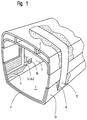
- FIG. 1 a vehicle structure 1 produced using winding technology is shown in cross-section and with a partially cut-open structure.
- the inner surface of the vehicle structure 1 is formed by an inner winding layer 5.
- An inner insulation layer 6 is applied over the inner winding layer 5, in which 6.1 cable channels 6.2 are inserted in recessed grooves.
- a device connection 16 is shown lying in a side wall above a cable duct 6.2.
- the inner insulation layer 6 is followed by a middle winding layer 7, on the top of which ceiling ducts 2 are placed in the form of a one-piece plastic profile in the roof area.
- the carriage windows 3 are located in the side walls in the subsequent outer insulation layer 8. Between the windows 3, an outer frame web 12 of a wrapped ring frame is visible.
- An outer winding layer 13 forms the outer skin of the vehicle structure 1.
- the section through the winding structure in FIG. 2 is shown in the window area of the vehicle structure 1. Partly Details already shown and named in FIG. 1 are enlarged and clearly shown here. Furthermore, the proportions of the individual layers are closer to reality.
- the structure begins on the inside with the first, the inner winding layer 5, which can have a thickness of, for example, two to five mm.
- Their structure preferably consists of resin-impregnated glass fiber layers in the form of rovings and fleeces.
- the inner insulation layer 6 placed and glued on this inner winding layer 5 is a few cm thick and can be made of a dimensionally stable, flexible and pressure-resistant foam plastic. In this inner insulation layer 6, the grooves 6.1 are cut out, cut out or milled out and then fitted with cable channels 6.2.
- Some cables 6.3 are inserted in the cable duct 6.2 shown.
- the cable channels 6.2 are preferably open in the direction of the inner winding layer and closed in the direction of the middle winding layer 7 lying thereon.
- the height of the cable ducts 6.2 corresponds to the thickness of the inner insulation layer 6 in order to obtain a flat contact surface for the middle winding layer 7.
- a first sandwich structure of the vehicle structure 1 is completed with this middle winding layer 7.
- prefabricated windows 3 are placed on the middle winding layer 7 and fixed in their final position.
- the windows 3 consist of an outer frame 3.1, an inner frame 3.3 connected with an adhesive joint 3.2 and a double glazing 3.4 used in the inner frame 3.3.
- the outer surfaces and the inner surfaces of the windows 3 are each covered with an easily removable protective film 4
- the area in the vertical alignment above and below the windows 3, as shown in FIG. 3, is filled all around the vehicle structure 1 with an outer insulation layer 8 of the same thickness as the outer window frames 3.1.
- a round frame 17 reinforcing the structure is wrapped with the next process steps.
- an inner frame web 9 is wound into the channel base in the form of a multi-layer winding.
- a frame core 11 is then inserted in the middle of the inner frame web 9, the width of which is, for example, approximately half the channel width, and which consists of a dimensionally stable, light core material.
- the height of the frame core 11 is a few mm less than the thickness of the window 3.
- Frame flanges 10 are wrapped in the side channels thus created up to the same height of the frame core 11.
- the outer frame web 12 is wound onto the insulation layer 11 and the two lateral frame flanges 10.
- the annular frame 17 forms a rectangular profile which reinforces the structure and has a stiffening core of great strength. With the appropriate choice of material, a strength comparable to that of a round metal frame is achieved.
- carbon fiber fabrics impregnated with special resin are processed as high-strength materials.
- the wrapped annular frame 17 forms with the outer insulation layer 8 and the outside of the window 3 a uniform flat surface as the basis for an outer winding layer 13 that closes the structure.
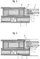
- FIG. 4 shows how the windows 3 covered by the outer winding layer 13 after the winding operations have been completed are exposed by cutting out this outer winding layer 13.
- the protective film 4 has been removed and a final joint 3.5 has been introduced, the outside of the structure is largely finished.
- the structural layers 5, 6 and 7 must be cut to match the contours of the windows 3, flush or flush with the inside edge of the outer frame 3.1, except for the surface of the inner frame 3.3. to expose the inside of the window 3, on which the protective film 4 is then also removed.
- an angle frame 14 covering the inner winding layer 5 is also used which covers a few cm.
- a reinforcing frame 15 is used as an additional element in this illustration on the outside of the structure near the window 3. With this reinforcement frame 15, increased requirements regarding strength and finish of the outer skin of a vehicle are met.
- FIG. 6 shows the perspective exterior view of the vehicle structure 1 in an intermediate stage essential for the method according to the invention.
- the first sandwich structure consisting of inner winding layer 5, inner insulation layer 6 and middle winding layer 7 is present here.
- the prepared molded part with the ceiling channels 2 is placed on the top and the windows 3 are attached in their final position on the sides.
- longitudinal stiffeners 18 are attached laterally at the level of the buffer level. These longitudinal stiffeners 18 provide the compressive strength required for a rail vehicle parallel to the longitudinal direction of the vehicle.
- the longitudinal stiffeners 18 are of the same type as the ring frames 17 and therefore also have the same mechanical strength. They are essentially designed as wound rectangular hollow profiles or pultrusion profiles with a foamed cavity, each have the length of a window 3 and are supported on the end faces of the ring ribs 17.
- longitudinal stiffeners 18 are also used in further locations between the ring frames 17 in the longitudinal direction, for example in the bottom and Ceiling area and on the corner parts of the vehicle structure 1.
- This vehicle structure 1 with the coherent reinforcement structure produced during the winding process, consisting of ring frames 17 and longitudinal reinforcements 18, the windows 3 used with the reinforcement frames 14, the ceiling channels 2, the three winding layers 5, 7, 13 and the two insulation layers 6 and 8 have a very high rigidity and strength with high quality of heat and sound insulation.
- FIG. 7 the spaces between the windows 3 and the longitudinal stiffeners 18 are filled with the outer insulation layer 8 and two of the three provided ring frames 17 are wrapped.
- the still empty, recessed channel for the third ring frame 17 is visible in the front.
- Ring frames 17 are used in a vehicle structure 1 for a car body not only between the windows 3, but also where structural reinforcement is sensible and necessary, for example in the case of door jambs as a supporting element for the door mechanism and as edge reinforcement at the car ends for the attachment of front parts and driver's cabins.
- the result of the method according to the invention is a double sandwich structure with an inner insulation layer 6 receiving cable channels 6.2, which is closed with an inner and middle winding layer 5 and 7 and an outer one, the stiffeners described in the form of the ring ribs 17 and longitudinal stiffeners 18 and the windows 3 and ceiling channels 2 receiving the outer insulation layer, which is finally covered with an outer winding layer 13.
- the cable channels 6.2 can be drilled at designated locations and device connections 16 can be made, such as for lighting and audio connections or for feeding private devices such as Razors, PC's, dictation machines, typewriters, etc. If necessary, the reinforcement frames 15 already described can be used on the outside of the windows.
- the inner frame part projecting into the adhesive joint 3.2 absorbs additional longitudinal forces in a force-locking connection with the ring ribs 17 and the outer visible part results in an aesthetically and mechanically satisfactory covering of the frame part of the window 3 and of the cutout in the outer winding layer 13.
Landscapes
- Engineering & Computer Science (AREA)
- Mechanical Engineering (AREA)
- Architecture (AREA)
- Structural Engineering (AREA)
- Chemical & Material Sciences (AREA)
- Combustion & Propulsion (AREA)
- Transportation (AREA)
- Body Structure For Vehicles (AREA)
- Recrystallisation Techniques (AREA)
- Vehicle Interior And Exterior Ornaments, Soundproofing, And Insulation (AREA)
- Holo Graphy (AREA)
- Transition And Organic Metals Composition Catalysts For Addition Polymerization (AREA)
- Laminated Bodies (AREA)
- Moulding By Coating Moulds (AREA)
- Seal Device For Vehicle (AREA)
- Bending Of Plates, Rods, And Pipes (AREA)
- Glass Compositions (AREA)
- Steroid Compounds (AREA)
Abstract
Description
Die vorliegende Erfindung bezieht sich auf ein Verfahren zur Herstellung von Fahrzeugstrukturen, vorzugsweise von Wagenkasten für Schienenfahrzeuge, mit selbsttragender Leichtbaustruktur aus faserverstärkten Kunststoffen, wobei mittels Wickeltechnik der zylindrische Längsteil eines Wagenkastens zusammen mit Verstärkungselementen, Installations- und Lüftungskanälen in kontinuierlich aufeinander folgenden Verfahrensschritten hergestellt wird.The present invention relates to a method for producing vehicle structures, preferably car bodies for rail vehicles, with a self-supporting lightweight structure made of fiber-reinforced plastics, the cylindrical longitudinal part of a car body being produced together with reinforcing elements, installation and ventilation ducts in continuously successive process steps by means of winding technology.
Aus der Patentschrift GB 1 490 575 ist ein im Wickelverfahren hergestellter Wagenkasten bekannt, der eine innere Wickelschicht mit zum Teil eingeformten, vorspringenden und rundumlaufenden Versteifungsrippen, ein eingewickeltes Versteifungsgerippe aus Metall und zwischen innerer und äusserer Wickelschicht Aussparungen zur Aufnahme von Lüftung, Heizung, Elektroinstallationen, Beleuchtung und sanitäre Einrichtungen aufweist. Der einfache Sandwich-Aufbau aus innerer Wickelschicht, Zwischenisolation und äusserer Wickelschicht bildet die selbsttragende Struktur des Wagenkastens.From the
Die europäische Patentanmeldung 0 554 539 beschreibt ein ähnliches Verfahren zur Herstellung eines Wagenkastens in Wickeltechnik. Zusätzlich zu einem Verstärkungsgerippe werden an den Ecken angeordnete spezielle Längsprofile eingewickelt, und werden für später auszuschneidende Fenster- und Türöffnungen entsprechende Blinddeckel eingesetzt. Diese ebenfalls selbsttragende Leichtbaustruktur weist eine dünne, erste, innere Isolationsschicht auf, sowie eine zweite, äussere Isolationsschicht, welche die Dicke der Verstärkungsprofile aufweist.European patent application 0 554 539 describes a similar method for producing a car body using winding technology. In addition to a reinforcement frame, special longitudinal profiles arranged at the corners are wrapped, and appropriate blind covers are used for later window and door openings. This also self-supporting lightweight structure has a thin, first, inner insulation layer, and a second, outer insulation layer, which has the thickness of the reinforcement profiles.
Bei beiden genannten Verfahren weisen die Isolationsschichten infolge der eingewickelten metallischen Verstärkungsteile partielle Wärmebrücken auf. Ferner birgt die Paarung grundverschiedener Materialien die Risiken von Wickelschichtablösung und Korrosion infolge auftretender Dillatationskräfte bei Temperaturschwankungen. Zudem bedeutet ein separat herzustellendes Verstärkungsgerippe einen konzeptionellen Fremdkörper, der einen kontinuierlichen Ablauf des Herstellprozesses stört oder verunmöglicht.In both of the methods mentioned, the insulation layers have partial thermal bridges as a result of the wrapped metallic reinforcement parts. The pairing also harbors fundamentally different materials, the risks of winding layer detachment and corrosion as a result of the occurring dillation forces with temperature fluctuations. In addition, a reinforcement frame to be manufactured separately means a conceptual foreign body that disrupts or makes it impossible for the manufacturing process to run continuously.
Der vorliegenden Erfindung liegt die Aufgabe zugrunde, ein Verfahren anzuwenden und entsprechende Materialien einzusetzen, die diese Risiken ausschliessen und die eine wirtschaftlichere Herstellung einer Wagenkastenstruktur ermöglichen.The present invention is based on the object of using a method and using corresponding materials which eliminate these risks and which enable a more economical production of a body structure.
Diese Aufgabe wird durch die in den Ansprüchen gekennzeichneten Merkmale gelöst.This object is achieved by the features characterized in the claims.
Die Vorteile der Erfindung bestehen im wesentlichen darin, dass der Aufbau der selbsttragenden Struktur aus gleichartigen Materialien besteht, dass der Aufwand für die Fenstermontage reduziert und die Wärmeisolation verbessert wird.The advantages of the invention essentially consist in the fact that the structure of the self-supporting structure consists of similar materials, that the effort for the window assembly is reduced and that the thermal insulation is improved.
Weitere Vorteile sind darin zu sehen, dass die Festigkeit der Fahrzeugstruktur durch die Verfahrensschritte und Materialwahl den jeweiligen Erfordernissen angepasst werden kann und dass die Strukturfestigkeit mittels externer und interner Mittel noch weiter beeinflusst werden kann.Further advantages can be seen in the fact that the strength of the vehicle structure can be adapted to the respective requirements through the process steps and the choice of material and that the structural strength can be influenced even further by external and internal means.
In den Zeichnungen ist ein Ausführungsbeispiel dargestellt und es zeigen:
- Fig.1 einen Querschnitt einer Fahrzeugstruktur mit teilweise aufgeschnittener Struktur,
- Fig.2 einen Querschnitt der Sandwichstruktur mit Fenster und Ringspant,
- Fig.3 einen Querschnitt der Sandwichstruktur ausserhalb des Fensterbereiches mit Ringspant,
- Fig.4 den gleichen Querschnitt mit freigelegten Fensterflächen,
- Fig.5 den gleichen Querschnitt mit eingesetztem Abdeck- und Verstärkungsrahmen,
- Fig.6 eine Aussenansicht der Fahrzeugstruktur im Fabrikationsstadium mit aufgeklebten Fenstern,
- Fig.7 eine Aussenansicht der Fahrzeugstruktur nach weiteren Verfahrensschritten und
- Fig.8 eine Aussenansicht der Fahrzeugstruktur nach Abschluss des Herstellverfahrens.
- 1 shows a cross section of a vehicle structure with a partially cut-open structure,
- 2 shows a cross section of the sandwich structure with window and ring frame,
- 3 shows a cross section of the sandwich structure outside the window area with an annular frame,
- 4 shows the same cross section with exposed window areas,
- 5 shows the same cross section with inserted cover and reinforcement frame,
- 6 shows an exterior view of the vehicle structure in the production stage with windows glued on,
- 7 shows an exterior view of the vehicle structure after further method steps and
- 8 shows an exterior view of the vehicle structure after completion of the manufacturing process.
Das erfindungsgemässe Verfahren und dessen wesentliche Schritte wird im folgenden anhand der Figuren näher erläutert.The method according to the invention and its essential steps are explained in more detail below with reference to the figures.
In der Fig.1 ist eine in Wickeltechnik hergestellte Fahrzeugstruktur 1 im Querschnitt und mit teilweise aufgeschnittener Struktur dargestellt. Die Innenfläche der Fahrzeugstruktur 1 wird von einer inneren Wickelschicht 5 gebildet. Ueber der inneren Wickelschicht 5 ist eine innere Isolationsschicht 6 aufgebracht, in welcher in ausgenommenen Nuten 6.1 Kabelkanäle 6.2 eingelegt sind. Ueber einem Kabelkanal 6.2 liegend ist in einer Seitenwand ein Geräteanschluss 16 dargestellt. Nach der inneren Isolationsschicht 6 folgt eine mittlere Wicklungsschicht 7, auf deren Oberseite im Dachbereich Deckenkanäle 2 in der Form eines einstückigen Kunststoffprofiles aufgelegt ist. In der darauf folgenden äusseren Isolationsschicht 8 befinden sich in den Seitenwänden die Wagenfenster 3. Zwischen den Fenstern 3 ist ein äusserer Spantsteg 12 eines eingewickelten Ringspantes sichtbar. Eine äussere Wickelschicht 13 bildet die Aussenhaut der Fahrzeugstruktur 1.In FIG. 1, a
Der Schnitt durch die Wickelstruktur in Fig.2 ist im Fensterbereich der Fahrzeugstruktur 1 dargestellt. Zum Teil bereits dargestellte und benannte Einzelheiten in der Fig.1 sind hier vergrössert und deutlich dargestellt. Ferner sind die Proportionen der einzelnen Schichten zueinander der Realität angenähert. Die Struktur beginnt innenseitig mit der ersten, der inneren Wickelschicht 5, die eine Stärke von beispielsweise zwei bis fünf mm aufweisen kann. Ihr Aufbau besteht vorzugsweise aus harzgetränkten Glasfaserlagen in der Form von Rovings und Vliesen. Die auf dieser inneren Wickelschicht 5 aufgelegte und geklebte innere Isolationsschicht 6 ist einige cm stark und kann aus einem formstabilen, biegeelastischen und drucksteifen Schaumkunststoff beschaffen sein. In diese innere Isolationsschicht 6 werden die Nuten 6.1 ausgespart, ausgeschnitten oder ausgefräst und dann mit Kabelkanälen 6.2 bestückt. Im dargestellten Kabelkanal 6.2 sind einige Kabel 6.3 eingelegt. Die Kabelkanäle 6.2 sind vorzugsweise in der Richtung zur inneren Wickelschicht offen und in Richtung zur darauf liegenden mittleren Wicklungsschicht 7 geschlossen. Die Höhe der Kabelkanäle 6.2 entspricht, zwecks Erhalt einer planen Auflagefläche für die mittlere Wickelschicht 7, der Stärke der inneren Isolationsschicht 6. Mit dieser mittleren Wickelschicht 7 ist ein erster Sandwich-Aufbau der Fahrzeugstruktur 1 abgeschlossen.The section through the winding structure in FIG. 2 is shown in the window area of the
Beim nächsten Verfahrensschritt werden vorfabrizierte Fenster 3 auf die mittlere Wickelschicht 7 aufgelegt und in ihrer endgültigen Lage fixiert. Die Fenster 3 bestehen aus einem äusseren Rahmen 3.1, einem mit einer Klebefuge 3.2 verbundenen inneren Rahmen 3.3 und einer im inneren Rahmen 3.3 eingesetzten Doppelverglasung 3.4. Die Aussenflächen und die Innenflächen der Fenster 3 sind je mit einer leicht abziehbaren Schutzfolie 4 überzogenIn the next process step, prefabricated
Die Fläche in der vertikalen Flucht oberhalb und unterhalb der Fenster 3 wird, wie in Fig.3 dargestellt, rundherum um die Fahrzeugstruktur 1 mit einer äusseren Isolationsschicht 8 von gleicher Dicke wie die äusseren Fensterrahmen 3.1 aufgefüllt.The area in the vertical alignment above and below the
In dem nun rundum laufenden freien Kanal mit der konstanten Breite eines Fensterpfostens wird mit den nächsten Verfahrensschritten ein die Struktur verstärkender Rundspant 17 eingewickelt. Als erstes Element des Rundspantes 17 wird in der Form einer mehrlagigen Wicklung in den Kanalgrund ein innerer Spantsteg 9 hineingewickelt. In der Mitte des inneren Spantsteges 9 wird dann ein Spantkern 11 eingesetzt, dessen Breite beispielsweise etwa die Hälfte der Kanalbreite beträgt, und der aus einem formstabilen, leichten Kernwerkstoff besteht. Die Höhe des Spantkerns 11 beträgt einige mm weniger als die Dicke der Fenster 3. In die so entstehenden Seitenkanäle werden Spantflansche 10 eingewickelt bis auf die gleiche Höhe des Spantkerns 11.In the now free running channel with the constant width of a window post, a
Als Abschlussteil des Ringspantes 17 wird auf die Isolationsschicht 11 und die beiden seitlichen Spantflansche 10 der äussere Spantsteg 12 aufgewickelt. Der Ringspant 17 bildet in der dargestellten Form ein die Struktur verstärkendes Rechteckprofil mit versteifendem Kern von grosser Festigkeit. Durch entsprechende Materialwahl wird eine mit einem Metallrundspant vergleichbare Festigkeit erreicht. Als hochfeste Materialien werden für den Ringspant 17 beispielsweise mit Spezialharz getränkte Kohlefasergewebe verarbeitet.As the end part of the
Der eingewickelte Ringspant 17 bildet mit der äusseren Isolationsschicht 8 und der Aussenseite der Fenster 3 eine gleichmässige plane Fläche als Grundlage für eine die Struktur abschliessende äussere Wickelschicht 13.The wrapped
Die Fig.4 zeigt, wie die nach Abschluss der Wickeloperationen von der äusseren Wickelschicht 13 überdeckten Fenster 3 durch Herausschneiden dieser äusseren Wickelschicht 13 freigelegt werden. Nach Abzug der Schutzfolie 4 und Einbringen einer Abschlussfuge 3.5 ist die Aussenseite der Struktur weitgehend fertig hergestellt. Auf der Innenseite müssen mit den Konturen der Fenster 3 übereinstimmend bzw. bündig mit der Innenkante des äusseren Rahmens 3.1 die Strukturschichten 5, 6 und 7 bis auf die Fläche des inneren Rahmens 3.3 durchgetrennt werden, um die Innenseite der Fenster 3 freizulegen, auf welcher dann auch noch die Schutzfolie 4 abgezogen wird.FIG. 4 shows how the
Auf der Innenseite der Struktur wird gemäss der Fig.5 zwecks Abdeckung der Schnittflächen der durchgetrennten Strukturschichten 5, 6, 7, des äusseren Winkels 3.1 und der Klebefuge 3.2 ein, die innere Wickelschicht 5 zusätzlich einige cm überdeckender, Winkelrahmen 14 eingesetzt. Als zusätzliches Element ist in dieser Darstellung auf der Aussenseite der Struktur beim Fenster 3 ein Verstärkungsrahmen 15 eingesetzt. Mit diesem Verstärkungsrahmen 15 werden erhöhte Forderungen bezüglich Festigkeit und Finish der Aussenhaut eines Fahrzeuges erfüllt.On the inside of the structure, in accordance with FIG. 5, in order to cover the cut surfaces of the cut
Die Fig.6 zeigt die perspektivische Aussenansicht der Fahrzeugstruktur 1 in einem für das erfindungsgemässe Verfahren wesentlichen Zwischenstadium. Es ist hier die erste Sandwichstruktur bestehend aus innerer Wickelschicht 5, innerer Isolationsschicht 6 und mittlerer Wicklungsschicht 7 vorhanden. Auf der Oberseite ist der vorbereitete Formteil mit den Deckenkanälen 2 aufgesetzt und auf den Seiten sind die Fenster 3 in ihrer endgültigen Lage angebracht.6 shows the perspective exterior view of the
Im gezeigten Beispiel sind, da es sich hier vorzugsweise um die Herstellung der Fahrzeugstruktur 1 für den Wagenkasten eines Schienenfahrzeuges handelt, je seitlich auf der Höhe der Pufferebene vorgefertigte Längsversteifungen 18 befestigt. Durch diese Längsversteifungen 18 erhält man die für ein Schienenfahrzeug geforderte Druckfestigkeit parallel zur Längsrichtung des Fahrzeuges. Die Längsversteifungen 18 sind material- und verfahrensmässig gleichartig wie die Ringspanten 17 und weisen deshalb auch mechanisch die gleiche Festigkeit auf. Sie sind im wesentlichen als gewickelte Rechteck-Hohlprofile oder Pultrusionsprofile mit ausgeschäumtem Hohlraum ausgebildet, weisen je die Länge eines Fensters 3 auf und stützen sich stirnseitig auf die Ringspanten 17 ab. Längsversteifungen 18 werden bei Bedarf auch noch an weiteren Stellen zwischen den Ringspanten 17 in Längsrichtung eingesetzt wie beispielsweise im Boden- und Deckenbereich und an den Eckpartien der Fahrzeugstruktur 1. Diese Fahrzeugstruktur 1 mit dem während dem Wickelverfahren erzeugten zusammenhängenden Verstärkungsgerippe bestehend aus Ringspanten 17 und Längsversteifungen 18, den eingesetzten Fenstern 3 mit den Verstärkungsrahmen 14, den Deckenkanälen 2, den drei Wickelschichten 5, 7, 13 und den beiden Isolationsschichten 6 und 8 weist eine sehr grosse Steifigkeit und Festigkeit bei hoher Güte der Wärme- und Schallisolation auf.In the example shown, since this is preferably the manufacture of the
In der Fig.7 sind die Zwischenräume zwischen den Fenstern 3 und den Längsversteifungen 18 mit der äusseren Isolationsschicht 8 aufgefüllt und sind zwei der drei vorgesehenen Ringspanten 17 eingewickelt. Vorne ist der noch leere, ausgesparte Kanal für den dritten Ringspant 17 sichtbar. Aus Platzgründen ist in den Fig.6-8 längenmässig nur ein Teilausschnitt einer Fahrzeugstruktur 1 dargestellt. Ringspanten 17 werden bei einer Fahrzeugstruktur 1 für einen Wagenkasten nicht nur zwischen den Fenstern 3 eingesetzt, sondern zusätzlich dort wo eine Strukturverstärkung sinnvoll und nötig ist wie beispielsweise bei Türpfosten als Tragelement für die Türmechanik und als Randversteifung an Wagenenden für den Anbau von Stirnteilen und Führerkabinen.In FIG. 7, the spaces between the
Die Fig.8 zeigt die fertige Fahrzeugstruktur 1 mit eingesetzten Verstärkungsrahmen 15 und Winkelrahmen 14.8 shows the
Das Resultat des erfindungsgemässen Verfahrens ist eine Doppelsandwichstruktur mit einer inneren, Kabelkanäle 6.2 aufnehmenden Isolationsschicht 6, die mit einer inneren und mittleren Wickelschicht 5 und 7 abgeschlossen ist und einer äusseren, die beschriebenen Versteifungen in der Form der Ringspanten 17 und Längsversteifungen 18 sowie die Fenster 3 und Deckenkanäle 2 aufnehmenden äusseren Isolationsschicht, die abschliessend mit einer äusseren Wickelschicht 13 überzogen wird. Von der Innenseite her können die Kabelkanäle 6.2 an vorgesehenen Stellen angebohrt und Geräteanschlüsse 16 ausgeführt werden wie beispielsweise für Beleuchtungs- und Audioanschlüsse oder für die Speisung privater Geräte wie Rasierer, PC's, Diktiergeräte, Schreibmaschinen etc. An der Aussenseite der Fenster können bei Bedarf die bereits beschriebenen Verstärkungsrahmen 15 eingesetzt werden. Der innere in die Klebefuge 3.2 hineinragende Rahmenteil nimmt in kraftschlüssiger Verbindung mit den Ringspanten 17 zusätzliche Längskräfte auf und der äussere sichtbare Teil ergibt eine ästhetisch und mechanisch befriedigende Abdeckung der Rahmenpartie des Fensters 3 und des Ausschnittes in der äusseren Wickelschicht 13.The result of the method according to the invention is a double sandwich structure with an
Claims (11)
Applications Claiming Priority (3)
| Application Number | Priority Date | Filing Date | Title |
|---|---|---|---|
| CH187194 | 1994-06-14 | ||
| CH187194 | 1994-06-14 | ||
| CH1871/94 | 1994-06-14 |
Publications (2)
| Publication Number | Publication Date |
|---|---|
| EP0687611A1 true EP0687611A1 (en) | 1995-12-20 |
| EP0687611B1 EP0687611B1 (en) | 2000-01-05 |
Family
ID=4220549
Family Applications (1)
| Application Number | Title | Priority Date | Filing Date |
|---|---|---|---|
| EP95107900A Expired - Lifetime EP0687611B1 (en) | 1994-06-14 | 1995-05-24 | Method for the manufacturing of vehicle structures |
Country Status (9)
| Country | Link |
|---|---|
| US (1) | US5669999A (en) |
| EP (1) | EP0687611B1 (en) |
| JP (1) | JPH07329778A (en) |
| AT (1) | ATE188422T1 (en) |
| AU (1) | AU685612B2 (en) |
| CA (1) | CA2150893A1 (en) |
| DE (1) | DE59507553D1 (en) |
| FI (1) | FI952870A (en) |
| NO (1) | NO305232B1 (en) |
Cited By (5)
| Publication number | Priority date | Publication date | Assignee | Title |
|---|---|---|---|---|
| FR2753673A1 (en) | 1996-09-25 | 1998-03-27 | Deutsche Waggonbau Ag | SHELL STRUCTURE IN PLASTIC MATERIAL ARMED WITH FIBERS FOR VEHICLES OR CONTAINERS, IN PARTICULAR FOR RAIL VEHICLE CASES |
| FR2760397A1 (en) * | 1997-03-06 | 1998-09-11 | Jean Alphonse David | Railway tanker body structural assembly |
| EP0982212A1 (en) | 1998-08-27 | 2000-03-01 | Inventio Ag | Device for force introduction into a component constructed of composite fibres |
| WO2001085517A1 (en) * | 2000-05-12 | 2001-11-15 | Constructions Industrielles De La Mediterranee (C.N.I.M.) | Method for producing a structure made of composite material for railway vehicles |
| DE10155820A1 (en) * | 2001-11-15 | 2003-06-05 | Bombardier Transp Gmbh | Railway passenger carriage body has inner and outer layers of a fiber compound material, with intermediate layers between them bonded by the fibers in a lightweight and stable structure |
Families Citing this family (25)
| Publication number | Priority date | Publication date | Assignee | Title |
|---|---|---|---|---|
| US6000342A (en) * | 1996-07-19 | 1999-12-14 | Trn Business Trust | Railway car underframe for an insulated composite boxcar |
| US6092472A (en) * | 1996-07-19 | 2000-07-25 | Trn Business Trust | Composite box structure for a railway car |
| USH1872H (en) * | 1997-03-03 | 2000-10-03 | The United States Of America As Represented By The Secretary Of The Air Force | Modular fiber reinforced plastic enclosed bridge |
| NL1006199C1 (en) * | 1997-03-14 | 1998-09-15 | Fokker Special Products | Vehicle construction. |
| DE19903281A1 (en) * | 1999-01-28 | 2000-08-03 | Abb Daimler Benz Transp | Rail vehicle with self-supporting car body |
| US6976333B2 (en) * | 2001-01-11 | 2005-12-20 | Steven Sims | Recoil reducing accessories for firearms |
| US6712390B1 (en) | 2001-07-06 | 2004-03-30 | Joseph P. Spinelli | Vehicular impact resistant barrier system |
| EP1706344A4 (en) * | 2004-01-23 | 2010-12-08 | First Green Park Pty Ltd | Panel constructions and assemblies made therefrom |
| US20050161975A1 (en) * | 2004-01-23 | 2005-07-28 | Nieminski Brant R. | Modular bus body assembly |
| US7721495B2 (en) * | 2005-03-31 | 2010-05-25 | The Boeing Company | Composite structural members and methods for forming the same |
| US8444087B2 (en) * | 2005-04-28 | 2013-05-21 | The Boeing Company | Composite skin and stringer structure and method for forming the same |
| US20060237588A1 (en) * | 2005-03-31 | 2006-10-26 | The Boeing Company | Composite structural member having an undulating web and method for forming the same |
| US7467763B2 (en) * | 2005-06-03 | 2008-12-23 | Kismarton Max U | Composite landing gear apparatus and methods |
| US20060222837A1 (en) * | 2005-03-31 | 2006-10-05 | The Boeing Company | Multi-axial laminate composite structures and methods of forming the same |
| US7740932B2 (en) * | 2005-03-31 | 2010-06-22 | The Boeing Company | Hybrid fiberglass composite structures and methods of forming the same |
| US7748119B2 (en) * | 2005-06-03 | 2010-07-06 | The Boeing Company | Method for manufacturing composite components |
| US20070052554A1 (en) * | 2005-08-24 | 2007-03-08 | The Boeing Company | Methods and systems for logistics health status display |
| US20070050104A1 (en) * | 2005-08-24 | 2007-03-01 | The Boeing Company | Methods and systems for logistics health status reasoner |
| DE102008027429B4 (en) * | 2008-06-09 | 2016-01-28 | Daimler Ag | Method for producing a bodyshell structure for a motor vehicle |
| TWI395683B (en) * | 2009-03-30 | 2013-05-11 | Kawasaki Heavy Ind Ltd | Railway vehicle structure and manufacturing method thereof |
| JP5271358B2 (en) * | 2009-06-10 | 2013-08-21 | 川崎重工業株式会社 | Method for reinforcing railway vehicle structure and railway vehicle structure |
| US8215692B2 (en) * | 2009-07-21 | 2012-07-10 | Navistar Canada, Inc. | Adjustable length delivery vehicle |
| JP2012020592A (en) * | 2010-07-12 | 2012-02-02 | Kawasaki Heavy Ind Ltd | Frame structure of railway vehicle |
| CA2813006A1 (en) * | 2010-09-20 | 2012-03-29 | Bombardier Transportation Gmbh | Lightweight compound cab structure for a rail vehicle |
| US9878773B2 (en) | 2012-12-03 | 2018-01-30 | The Boeing Company | Split resistant composite laminate |
Citations (3)
| Publication number | Priority date | Publication date | Assignee | Title |
|---|---|---|---|---|
| GB1490575A (en) | 1974-12-02 | 1977-11-02 | Pikaz Inzenyrsky Podnik | Body for a road or rail vehicle or for a container |
| EP0554539A1 (en) | 1992-01-28 | 1993-08-11 | Inventio Ag | Process for manufacturing a monogue coach body |
| EP0582544A1 (en) * | 1992-08-05 | 1994-02-09 | Alusuisse-Lonza Services Ag | Body of railway vehicles |
Family Cites Families (3)
| Publication number | Priority date | Publication date | Assignee | Title |
|---|---|---|---|---|
| US4025675A (en) * | 1973-12-19 | 1977-05-24 | Messerschmitt-Bolkow-Blohm Gmbh | Reinforced laminates |
| ATE149913T1 (en) * | 1992-07-10 | 1997-03-15 | Inventio Ag | METHOD FOR THE INTEGRAL PRODUCTION OF AN INTERIOR FOR A CAR BODY |
| FR2700729B1 (en) * | 1993-01-25 | 1995-03-31 | David Jean | Method for manufacturing a box with multicellular walls in thermosetting composite materials produced by winding. |
-
1995
- 1995-05-24 AT AT95107900T patent/ATE188422T1/en not_active IP Right Cessation
- 1995-05-24 EP EP95107900A patent/EP0687611B1/en not_active Expired - Lifetime
- 1995-05-24 DE DE59507553T patent/DE59507553D1/en not_active Expired - Fee Related
- 1995-06-02 CA CA002150893A patent/CA2150893A1/en not_active Abandoned
- 1995-06-09 AU AU20591/95A patent/AU685612B2/en not_active Ceased
- 1995-06-12 US US08/489,500 patent/US5669999A/en not_active Expired - Fee Related
- 1995-06-12 FI FI952870A patent/FI952870A/en unknown
- 1995-06-13 NO NO952319A patent/NO305232B1/en not_active IP Right Cessation
- 1995-06-14 JP JP7147425A patent/JPH07329778A/en active Pending
Patent Citations (3)
| Publication number | Priority date | Publication date | Assignee | Title |
|---|---|---|---|---|
| GB1490575A (en) | 1974-12-02 | 1977-11-02 | Pikaz Inzenyrsky Podnik | Body for a road or rail vehicle or for a container |
| EP0554539A1 (en) | 1992-01-28 | 1993-08-11 | Inventio Ag | Process for manufacturing a monogue coach body |
| EP0582544A1 (en) * | 1992-08-05 | 1994-02-09 | Alusuisse-Lonza Services Ag | Body of railway vehicles |
Cited By (6)
| Publication number | Priority date | Publication date | Assignee | Title |
|---|---|---|---|---|
| FR2753673A1 (en) | 1996-09-25 | 1998-03-27 | Deutsche Waggonbau Ag | SHELL STRUCTURE IN PLASTIC MATERIAL ARMED WITH FIBERS FOR VEHICLES OR CONTAINERS, IN PARTICULAR FOR RAIL VEHICLE CASES |
| FR2760397A1 (en) * | 1997-03-06 | 1998-09-11 | Jean Alphonse David | Railway tanker body structural assembly |
| EP0982212A1 (en) | 1998-08-27 | 2000-03-01 | Inventio Ag | Device for force introduction into a component constructed of composite fibres |
| WO2001085517A1 (en) * | 2000-05-12 | 2001-11-15 | Constructions Industrielles De La Mediterranee (C.N.I.M.) | Method for producing a structure made of composite material for railway vehicles |
| FR2808756A1 (en) * | 2000-05-12 | 2001-11-16 | Mediterranee Const Ind | Forming railway vehicle, etc by applying fiber reinforced skin to mandrel, then fitting framework of foam cells and applying another layer of fibers and resin over framework |
| DE10155820A1 (en) * | 2001-11-15 | 2003-06-05 | Bombardier Transp Gmbh | Railway passenger carriage body has inner and outer layers of a fiber compound material, with intermediate layers between them bonded by the fibers in a lightweight and stable structure |
Also Published As
| Publication number | Publication date |
|---|---|
| NO305232B1 (en) | 1999-04-26 |
| FI952870A0 (en) | 1995-06-12 |
| DE59507553D1 (en) | 2000-02-10 |
| FI952870A (en) | 1995-12-15 |
| US5669999A (en) | 1997-09-23 |
| JPH07329778A (en) | 1995-12-19 |
| NO952319L (en) | 1995-12-15 |
| EP0687611B1 (en) | 2000-01-05 |
| AU685612B2 (en) | 1998-01-22 |
| AU2059195A (en) | 1995-12-21 |
| NO952319D0 (en) | 1995-06-13 |
| CA2150893A1 (en) | 1995-12-15 |
| ATE188422T1 (en) | 2000-01-15 |
Similar Documents
| Publication | Publication Date | Title |
|---|---|---|
| EP0687611B1 (en) | Method for the manufacturing of vehicle structures | |
| DE69003682T2 (en) | MOISTURE-READY-RELEASE SPACER PROFILE FOR INSULATING GLASS. | |
| EP1288077B1 (en) | Roof liner in sandwich design and method of making the same | |
| DE3722490A1 (en) | FLOOR PLATE FOR A MOTOR VEHICLE | |
| DE10326503A1 (en) | Composite aluminium profile for windows and doors comprises inner and outer aluminium half shells with connecting and fixing means on soft plastics profile which can be fixed in some way in interspace | |
| DE19751277C2 (en) | Windows, doors or the like | |
| DE2841177A1 (en) | PASSENGER VEHICLE WITH GLUE-IN GLASS WINDOWS | |
| DE69929447T2 (en) | A STRUCTURAL ELEMENT THAT AT LEAST MERGES A PART OF THE CASE OF THE VEHICLE BOX OF A RAIL VEHICLE | |
| EP0062166A2 (en) | Sound-proofed apparatus housing, and method for its manufacture | |
| DE19649526C2 (en) | Vehicle head of a railway vehicle with a driver's cab | |
| DE69021113T2 (en) | Railway passenger car body and its manufacturing process. | |
| DE3101551C2 (en) | Door frame | |
| DE3608306A1 (en) | ROOF TRAINING OF COMMERCIAL VEHICLES | |
| EP0756979A1 (en) | Drivers cabin for the car body of a railway vehicle | |
| WO2008092699A1 (en) | Inspection device, in particular inspection cover | |
| DE19739291C1 (en) | Cut=outs for windows in fibre reinforced sandwich structure | |
| DE8619573U1 (en) | Reinforcing supports for profile strips | |
| DE29608643U1 (en) | Car body of a rail vehicle | |
| DE3346818C2 (en) | Roller conveyor | |
| DE69401079T2 (en) | Window frames for vehicle doors and their manufacture | |
| DE1580992A1 (en) | Method for manufacturing the structure of a vehicle, in particular the structure of a railroad car for passenger traffic | |
| DE3520479C1 (en) | Motor-vehicle door | |
| DE202007013805U1 (en) | Chassis part for wagon bodies | |
| DE3408995C2 (en) | Corner connection for profile parts | |
| DE8128016U1 (en) | "STOP PROFILE MADE OF ELASTIC MATERIAL" |
Legal Events
| Date | Code | Title | Description |
|---|---|---|---|
| PUAI | Public reference made under article 153(3) epc to a published international application that has entered the european phase |
Free format text: ORIGINAL CODE: 0009012 |
|
| AK | Designated contracting states |
Kind code of ref document: A1 Designated state(s): AT BE CH DE DK ES FR GB IT LI PT SE |
|
| 17P | Request for examination filed |
Effective date: 19960517 |
|
| 17Q | First examination report despatched |
Effective date: 19970904 |
|
| GRAG | Despatch of communication of intention to grant |
Free format text: ORIGINAL CODE: EPIDOS AGRA |
|
| GRAG | Despatch of communication of intention to grant |
Free format text: ORIGINAL CODE: EPIDOS AGRA |
|
| GRAH | Despatch of communication of intention to grant a patent |
Free format text: ORIGINAL CODE: EPIDOS IGRA |
|
| GRAH | Despatch of communication of intention to grant a patent |
Free format text: ORIGINAL CODE: EPIDOS IGRA |
|
| GRAA | (expected) grant |
Free format text: ORIGINAL CODE: 0009210 |
|
| AK | Designated contracting states |
Kind code of ref document: B1 Designated state(s): AT BE CH DE DK ES FR GB IT LI PT SE |
|
| PG25 | Lapsed in a contracting state [announced via postgrant information from national office to epo] |
Ref country code: SE Free format text: THE PATENT HAS BEEN ANNULLED BY A DECISION OF A NATIONAL AUTHORITY Effective date: 20000105 Ref country code: IT Free format text: LAPSE BECAUSE OF FAILURE TO SUBMIT A TRANSLATION OF THE DESCRIPTION OR TO PAY THE FEE WITHIN THE PRE;WARNING: LAPSES OF ITALIAN PATENTS WITH EFFECTIVE DATE BEFORE 2007 MAY HAVE OCCURRED AT ANY TIME BEFORE 2007. THE CORRECT EFFECTIVE DATE MAY BE DIFFERENT FROM THE ONE RECORDED.SCRIBED TIME-LIMIT Effective date: 20000105 Ref country code: GB Free format text: LAPSE BECAUSE OF FAILURE TO SUBMIT A TRANSLATION OF THE DESCRIPTION OR TO PAY THE FEE WITHIN THE PRESCRIBED TIME-LIMIT Effective date: 20000105 Ref country code: FR Free format text: LAPSE BECAUSE OF FAILURE TO SUBMIT A TRANSLATION OF THE DESCRIPTION OR TO PAY THE FEE WITHIN THE PRESCRIBED TIME-LIMIT Effective date: 20000105 Ref country code: ES Free format text: THE PATENT HAS BEEN ANNULLED BY A DECISION OF A NATIONAL AUTHORITY Effective date: 20000105 |
|
| REF | Corresponds to: |
Ref document number: 188422 Country of ref document: AT Date of ref document: 20000115 Kind code of ref document: T |
|
| REG | Reference to a national code |
Ref country code: CH Ref legal event code: EP |
|
| REF | Corresponds to: |
Ref document number: 59507553 Country of ref document: DE Date of ref document: 20000210 |
|
| PG25 | Lapsed in a contracting state [announced via postgrant information from national office to epo] |
Ref country code: PT Free format text: LAPSE BECAUSE OF FAILURE TO SUBMIT A TRANSLATION OF THE DESCRIPTION OR TO PAY THE FEE WITHIN THE PRESCRIBED TIME-LIMIT Effective date: 20000405 Ref country code: DK Free format text: LAPSE BECAUSE OF FAILURE TO SUBMIT A TRANSLATION OF THE DESCRIPTION OR TO PAY THE FEE WITHIN THE PRESCRIBED TIME-LIMIT Effective date: 20000405 |
|
| PG25 | Lapsed in a contracting state [announced via postgrant information from national office to epo] |
Ref country code: AT Free format text: LAPSE BECAUSE OF NON-PAYMENT OF DUE FEES Effective date: 20000524 |
|
| PG25 | Lapsed in a contracting state [announced via postgrant information from national office to epo] |
Ref country code: BE Free format text: LAPSE BECAUSE OF NON-PAYMENT OF DUE FEES Effective date: 20000531 |
|
| EN | Fr: translation not filed | ||
| GBV | Gb: ep patent (uk) treated as always having been void in accordance with gb section 77(7)/1977 [no translation filed] |
Effective date: 20000105 |
|
| PLBE | No opposition filed within time limit |
Free format text: ORIGINAL CODE: 0009261 |
|
| STAA | Information on the status of an ep patent application or granted ep patent |
Free format text: STATUS: NO OPPOSITION FILED WITHIN TIME LIMIT |
|
| BERE | Be: lapsed |
Owner name: INVENTIO A.G. Effective date: 20000531 |
|
| 26N | No opposition filed | ||
| PGFP | Annual fee paid to national office [announced via postgrant information from national office to epo] |
Ref country code: DE Payment date: 20020511 Year of fee payment: 8 |
|
| PGFP | Annual fee paid to national office [announced via postgrant information from national office to epo] |
Ref country code: CH Payment date: 20020816 Year of fee payment: 8 |
|
| PG25 | Lapsed in a contracting state [announced via postgrant information from national office to epo] |
Ref country code: LI Free format text: LAPSE BECAUSE OF NON-PAYMENT OF DUE FEES Effective date: 20030531 Ref country code: CH Free format text: LAPSE BECAUSE OF NON-PAYMENT OF DUE FEES Effective date: 20030531 |
|
| PG25 | Lapsed in a contracting state [announced via postgrant information from national office to epo] |
Ref country code: DE Free format text: LAPSE BECAUSE OF NON-PAYMENT OF DUE FEES Effective date: 20031202 |
|
| REG | Reference to a national code |
Ref country code: CH Ref legal event code: PL |