EP0687104B1 - A method for detecting edge direction in an interlaced television image - Google Patents
A method for detecting edge direction in an interlaced television image Download PDFInfo
- Publication number
- EP0687104B1 EP0687104B1 EP19950108074 EP95108074A EP0687104B1 EP 0687104 B1 EP0687104 B1 EP 0687104B1 EP 19950108074 EP19950108074 EP 19950108074 EP 95108074 A EP95108074 A EP 95108074A EP 0687104 B1 EP0687104 B1 EP 0687104B1
- Authority
- EP
- European Patent Office
- Prior art keywords
- main
- minimum
- dir
- horizontal
- group
- Prior art date
- Legal status (The legal status is an assumption and is not a legal conclusion. Google has not performed a legal analysis and makes no representation as to the accuracy of the status listed.)
- Expired - Lifetime
Links
Images

Classifications
-
- H—ELECTRICITY
- H04—ELECTRIC COMMUNICATION TECHNIQUE
- H04N—PICTORIAL COMMUNICATION, e.g. TELEVISION
- H04N7/00—Television systems
- H04N7/01—Conversion of standards, e.g. involving analogue television standards or digital television standards processed at pixel level
- H04N7/0117—Conversion of standards, e.g. involving analogue television standards or digital television standards processed at pixel level involving conversion of the spatial resolution of the incoming video signal
- H04N7/012—Conversion between an interlaced and a progressive signal
-
- H—ELECTRICITY
- H04—ELECTRIC COMMUNICATION TECHNIQUE
- H04N—PICTORIAL COMMUNICATION, e.g. TELEVISION
- H04N5/00—Details of television systems
- H04N5/14—Picture signal circuitry for video frequency region
Definitions
- the invention relates to a method for detecting and encoding edges in an interlaced video signal.
- edge detection a window is employed in which operator responses are calculated in several directions.
- edge detection is of utmost importance in object detection. When one looks at an object one perceives it by looking at its edges and angles and their jaggedness and sharpness. Therefore, in image processing, it is important to identify the local image contents and process the image accordingly. Jaggedness, line breaking, and unsharpness of edge regions as well as blurring of details in the image, which are typical of known methods especially when using a fixed algorithm, are highly dependent of the direction of the edge region.
- the purpose of edge detection is to examine which is the correct interpolation direction, sharpening direction, etc. To find that out, one has to obtain reliable edge information about the surroundings of the pixel to be processed. When the direction has been found out, it is possible to choose a processing method suitable for that direction.
- edge adaptive interpolation can be used to convert an interlaced normal definition image (720*576/50/2:1) either to a non-interlaced image (720*576/50/1:1), an image with a doubled field frequency (720*576/100/2:1), or to an image with a doubled vertical and horizontal line rate (1440*1152/50/2:1). In all these conversions it is possible to use the same edge detection method.
- Finnish patent FI-89995 corresponding to EP-A-550231 presents an efficient edge detector operating in a 6*3 window, capable of detecting an edge in nine directions.
- the detection takes place inside a field.
- Figure 1 shows a 6*3 window used in the detection which comprises 6 adjacent pixels c1, c2, c3, c4, c5 and c6 on the line m-1 and, likewise, 6 adjacent pixels c7, c8, c9, c10, c11 and c12 on the next line m+1 of the same field t.
- the value, marked with a question mark (?) of the edge estimate of the pixel on the line interpolated in between has to be calculated.
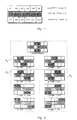
- Figures 2a...i show possible edge line directions and the pixel pairs taken into account in the calculation in each case.
- the edge line is at an angle of 90 degrees; in Figures b, d, f and h, whether the line is inclined to the left in the direction of 116, 135, 146 and 154 degrees, and in Figures c, e, g and i, whether the line is inclined to the right in the direction of 26, 34, 45 and 64 degrees.
- the minimum response for each group is found out.
- the minimum response of each group has been found out, the smallest of the minimum values is found out, the minimum of the minimums, which will be marked TOTmin.
- the estimate for the pixel on the right side of the pixel marked with a question mark is calculated, then the estimates for the pixels of the line to be interpolated next are calculated, until a sufficient amount of edge information from the neighbourhood of the interpolated pixel marked with a question mark has been stored in memory.
- the final edge information in the edge information correctness checking circuit is next selected, which circuit, by comparing the edge information to the edge information of the neighbouring pixels and using a suitable consistency check, decides whether the edge information is acceptable. After that, the image may be further processed in the direction indicated by the edge information.
- the edge detection method described above is based on the assumption that the deviation of luminance values is low along an edge whereas across an edge the deviation is high.
- the deviation is measured as an absolute difference of luminance values.
- the edge information is obtained by calculating the absolute differences in the various directions and selecting the direction with the smallest response as edge direction. If edge detection is carried out in a noisy location or close to narrow lines, it is possible to obtain small responses in several directions, in which case it is difficult to find out the correct direction. It is a disadvantage of the method described above that it does not provide information about whether or not a certain point is an edge point, and another disadvantage is that it is not capable of detecting a horizontal edge. Therefore, determining the edge direction by examining a single location does not provide an entirely reliable picture of the edge direction.
- This goal is achieved according to the enclosed claims as follows: in the neighbourhood of the location examined the dominant edge direction is found out. Then a few direction candidates for each examined position in the field are assigned, and then the number of incorrect candidates is reduced on the basis of a suitable criterion in order to increase the probability for the correct direction. The probability is increased by
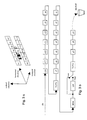
- Figure 3a shows a window used in the detection.
- the window is the size of 7*3 but any n*3 window can be used.
- the top row of the window consists of 7 adjacent pixels c1, c2, c3, c4, c5, c6 and c7 from the line m-1 and, likewise, 7 adjacent pixels c8, c9, c10, c11, c12, c13 and c14 from the next line m+1 of the same field t.
- the value of the edge estimate, marked with X has to be calculated. This estimate can be thought of as e.g. the edge information of the pixel on the line interpolated in between.
- the calculation of the direction estimate is an intra-field process, it uses only pixels c1, ..., c14 of field t, in other words, the top and bottom row of the window are used.
- the creation of new samples according to the edge information is performed simultaneously with the edge detection. If the algorithm exploiting the edge detection, say, interpolation, is an inter-field process, then pixels p3, p4 and p5 are also brought into the window from the preceding field t-1. Let it be pointed out that these pixels are not used in the edge detection itself, but the edge detection is purely an intra-field process.
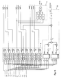
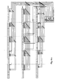
- Figure 3b illustrates the memory arrangement for forming the calculation window. It is intended for a case where the video signal complies to the PAL system and the active sample space is 720*576. If the number of digitized samples differs from the above, the size of the line and field memories is of course different.
- the arrangement simply comprises successive pixel memories c1, c2, c3, c4, c5, c6, c7 and c8, c9, c10, c11, c12, c13 and c14, and a delay between these two groups of seven pixels, which corresponds to the line duration minus the width of the window, or in this case delayed for 713 pixel delays. The delay is marked 713*D.
- the top and bottom rows of the window are obtained from the outputs of the pixel memories. Then follows the field memory (286LM) consisting of 286 line delays. If the line of the preceding field in the window is even-numbered, it is obtained from the output of the field memory delayed by the time that corresponds to 715 pixel memories (715*D), and if it is odd, it is obtained from the output of the field memory delayed by one line and in said 715 pixel memories. Selection is performed with a controlled switch as shown in the figure. The samples of the middle row in the window, ie. those of the preceding field, are obtained from the outputs of pixel memories p5, p4 and p3. On the basis of the figure, the forming of the window is clear to a person skilled in the art.
- the video signal samples arrive in block C14, travel through all successive memories and leave at pixel memory p3, which thus yields the temporally oldest sample.
- the samples p3, p4 and p5 of the preceding field are needed only if the image is converted from normal definition raster to high definition raster or from interlaced to progressive (IPC). In the latter case, the conversion is done so that the intermediate sample for the 3-point median filter is taken from the preceding field. Therefore a field memory is needed. If the conversion were field rate upconversion (FRU), then two field memories would be needed. In the edge direction estimation it suffices to have the pixel memories and one line memory between them.
- FRU field rate upconversion
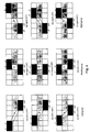
- a local direction is calculated using nine direction operators inside the window, shown in Figures 4a...4i.
- the difference of the absolute values of the current pixels indicated by the arrowheads in the window is first calculated, and then the sum of the differences is calculated. This is done in all nine directions.
- the marking left4 means that this is the fourth operator in the group where there are 4 operator pairs inclined to the left, and the degree shows the amount of inclination.
- the sum of the absolute differences, ie. the operator response left4 is
- the sum of the absolute differences is calculated in the same manner in all nine directions and the sums are stored in memories for further processing.
- the operators are divided into three groups: the left group comprising operators left2, left3 and left4; the middle group comprising operators right1, vertical and left1; and the right group comprising operators right2, right3 and right4.
- the mathematical expressions for the sums of the differences in all directions, divided into groups mentioned above, are as follows:
- the horizontal direction response is based on the same assumption that is used for the other directions: the deviation of sample values is low along an edge whereas across an edge the deviation is high. Thus, it is calculated maximum(c3, c4, c5) - minimum(c3, c4, c5) and maximum(c10, c11, c12) - minimum(c10, c11, c12). The sum of these two is then subtracted from the absolute difference of the two vertically aligned samples c4, c11, thus yielding the horizontal response as a result. Therefore, the greater the vertical difference and the smaller the horizontal difference, the greater the horizontal response and, thus, the probability for there being a horizontal edge in that location of the image. This information can be used in further processing of the image, e.g.
- the horizontal operator may be different from the one described above.
- the essential thing is that it is based on the comparison of responses of vertical and horizontal directions.
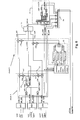
- Block A comprises calculation means to calculate eighteen absolute differences simultaneously and to sum the sums of the differences in pairs. Inside each calculation part there is marked the calculating operation it performs. The operator responses are obtained from the output of block A. The horizontal operator response is calculated in block B.
- the groups of three samples c3, c4, c5 and c10, c11, c12 are arranged in the order of magnitude of the samples in the sorting blocks and the differences of maximum and minimum of the sample values of the blocks are calculated and then summed and the sign of the sum is changed to the opposite.
- the difference of the sample values c4-c11 is added to the negative sum and the result is thresholded with the number k1, thus yielding the horizontal operator response.
- the activity check can also be done in a way different from the one described above. For example, it is possible to examine the absolute difference of two samples or the difference of the maximum and minimum in a group of three samples. Then the position is considered active if abs(c4-c11) > k2, or [max(c3,c4,c5) - min(c3,c4,c5)] > k2, or [max(c10,c11,c12) - minmin(c10,c11,c12)] )] > k2 k2 is a selectable threshold value which could be 16, for example.
- the responses are further processed according to Figure 6 both in the main and subdirections so that the responses left2, left3 and left4 of the left group comprise the left main direction, the responses left1, vertical and right1of middle group Rk comprise the middle main direction, and the responses right2, right3 and right4 of the right group comprise the right main direction.
- the responses of each main direction are taken to the appropriate block MIN, which finds out the minimum response among the input responses.
- the responses can be labelled e.g. in the following manner: a three-bit field is reserved for each main direction and bit "1" is used to indicate the subdirection.
- the preventing is done as follows: output 1 of the comparison block 52 is taken to a multiplier m1, the other input of which is the value 256. Then the output of the multiplier is 256, which will be summed with the minimum response of the left direction. The minimum response of the right direction remains unchanged since said value 1 is inverted before the multiplier m2. If the comparison block outputs a "0", the process is inverse to the above. So, Check A always manipulates the minimum response either in the left or in the right direction and makes it useless by changing its value into the biggest possible.
- the response direction information from the left and right groups ie. the direction information dir_left and dir_right are stored in memory 51 as is also the information on the correctness probability of these directions calculated in the comparison block 52.
- a trial interpolation is performed in block B (Check B), using the subdirections (dir_left or dir_right) stored in memory 51 and calculated in connection with the search for the minimum response of the right and the left main direction.
- This stage requires precalculated interpolation values for at least the left and the right group. In practice, however, it is the most straightforward method to calculate all possible values and store them in the memory 51 (9 memory locations) and then select one of them by means of three control signals: the subdirections dir_left, dir_right mentioned above and the one of those two that was used.
- the trial interpolation value y is compared to the sample c4 above and sample c11 below the zero sample X. This is done by calculating the difference of these samples and the trial value y.
- the next stage is to find the smallest of the main direction minimum responses (dir_totmin).
- the search is done in block 53 ( Figure 6), where the minimum responses resp_left, resp_right and resp_middle of the three main directions, which are the block's inputs, are arranged in the order of magnitude, and the smallest of them, marked with dir_totmin, is chosen for the output. It can be marked with a three-bit code word.
- Block E is optional. If the angle is e.g. between 45° and 64°, ie. between two groups (middle and right), there will appear a small "coupling error" in the image. Therefore, it is possible to add block E producing "intermediate groups" right_middle and left_middle. These operate in connection with the search for dominant direction in a way corresponding to that of the main groups.
- By means of AND and OR operations performed in block E it is examined whether dir_totmin belongs to the intermediate groups or not. The AND operation compares the dir_totmin value to the dir_right, dir_middle and dir_left values, ie. the following logic AND operations are performed:
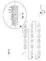
- Figure 7a shows a possible memory configuration used in the consistency check.
- the window used in the check is here a 5*3 window, so it comprises fifteen 16-bit memory units e1, e2, ..., e15 described above, each of which contains the edge information associated with the pixel.
- a bit of information in a unit is represented in the true/false fashion with one bit. This approach does not optimize the memory size needed but makes encoding very feasible.
- the size requirement for the memory used in the consistency check is about 2x720x16 bits. Since there is in the window edge information from three successive lines, two line memories are also needed, both comprising 715 pixel delays.
- Figures 8a and 8b show how the preliminary direction information is used for determining the interpolation direction in the consistency check.
- a window is used the size of which can be freely chosen. In this example the size of the window is 5*3. With the window size selection it is possible to slightly weigh the direction in which the edge direction will most likely be.
- the basic idea here is to find a dominant direction in a 5*3 window by counting the number of main directions, which are left, middle, right and horizontal. If the optional block E shown in Figure 6 is used, then there are also the intermediate directions left_middle and right_middle. It should be noted that calculations are not performed symmetrically in all fifteen positions, but only 11 directions are taken into account in the counting.
- the edge information e1, e2, e3, e6, e7, e8, e9, e10, e13, e14 and e15 are taken into account.
- the edge position In order to be valid the edge position must be active (there is no need for a special activity bit, but it can be coded so that zeros in all directions mean inactive).
- the total number of active positions within the 5x3 region is calculated (act count) and half of the act count specifies the minimum amount required for a main direction to be a dominant direction.
- the subdirection of the main direction in this position is set as the interpolation direction.
- the default interpolation direction is the subdirection (dir_middle) of the middle main direction.
- the interpolation direction is now known. However, to reduce coupling errors the consistency of the interpolation direction can be further improved as shown in Figure 9. Three successive positions in a line are considered to determine the required final interpolation direction for the position e8. If the interpolation direction in the position e8 has been selected from either the left or the right main direction and if both e7 and e9 have been selected from the middle interpolation direction, then the selected direction in e8 is not consistent and it has to be changed. In this case, the direction of the position e7 is used.
- the edge direction for each sample of an interlaced video signal has been reliably found out.
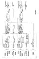
- This edge information can be used in many ways when processing the image. If an interlaced video signal complying with the 625/2:1/50 Hz standard is converted into a progressive 625/1:1/50 Hz signal or into a 625/2:1/100 Hz signal with a doubled field frequency or into a 1250/2:1/50 Hz signal, then new lines have to be interpolated. There are grounds for performing the line pixel interpolation adaptively on the basis of the edge information. Then a suitable interpolator would be e.g. an interpolator similar to the one shown in Figure 9 of the Finnish patent no. 89995.
- FIG. 10 is a diagrammatic illustration of an FMH-type interpolator of said patent application, adapted to this invention.
- There the averages for the input sample pairs in two-point linear filters are first calculated, and these serve as inputs for three-point median filters.
Landscapes
- Engineering & Computer Science (AREA)
- Multimedia (AREA)
- Signal Processing (AREA)
- Computer Graphics (AREA)
- Image Analysis (AREA)
- Compression Or Coding Systems Of Tv Signals (AREA)
Applications Claiming Priority (2)
| Application Number | Priority Date | Filing Date | Title |
|---|---|---|---|
| FI942750 | 1994-06-10 | ||
| FI942750A FI96559C (fi) | 1994-06-10 | 1994-06-10 | Menetelmä reunan suunnan tunnistamiseksi lomitellussa televisiokuvassa |
Publications (3)
| Publication Number | Publication Date |
|---|---|
| EP0687104A2 EP0687104A2 (en) | 1995-12-13 |
| EP0687104A3 EP0687104A3 (fi) | 1996-01-17 |
| EP0687104B1 true EP0687104B1 (en) | 1998-08-19 |
Family
ID=8540895
Family Applications (1)
| Application Number | Title | Priority Date | Filing Date |
|---|---|---|---|
| EP19950108074 Expired - Lifetime EP0687104B1 (en) | 1994-06-10 | 1995-05-26 | A method for detecting edge direction in an interlaced television image |
Country Status (3)
| Country | Link |
|---|---|
| EP (1) | EP0687104B1 (fi) |
| DE (1) | DE69504140T2 (fi) |
| FI (1) | FI96559C (fi) |
Cited By (1)
| Publication number | Priority date | Publication date | Assignee | Title |
|---|---|---|---|---|
| WO2011130051A1 (en) * | 2010-04-12 | 2011-10-20 | Sony Corporation | Context adaptive directional intra prediction |
Families Citing this family (8)
| Publication number | Priority date | Publication date | Assignee | Title |
|---|---|---|---|---|
| MY117289A (en) * | 1996-01-17 | 2004-06-30 | Sharp Kk | Image data interpolating apparatus |
| DE69605018T2 (de) * | 1996-02-13 | 2000-06-08 | St Microelectronics Srl | Kantenorientiertes Intrabild- und Zwischenbildinterpolationsfilter für Videogeräte besserer Qualität |
| US6421090B1 (en) * | 1999-08-27 | 2002-07-16 | Trident Microsystems, Inc. | Motion and edge adaptive deinterlacing |
| EP1191785A1 (en) * | 2000-09-21 | 2002-03-27 | Sony International (Europe) GmbH | Interlace to progresssive conversion |
| JP4108969B2 (ja) * | 2000-12-14 | 2008-06-25 | 松下電器産業株式会社 | 画像角度検出装置およびそれを備えた走査線補間装置 |
| GB2402288B (en) * | 2003-05-01 | 2005-12-28 | Imagination Tech Ltd | De-Interlacing of video data |
| KR100979811B1 (ko) | 2003-08-12 | 2010-09-02 | 삼성전자주식회사 | 수평 방향 에지의 패턴을 고려한 순차주사화 장치 및 방법 |
| TWI381732B (zh) * | 2008-10-08 | 2013-01-01 | Silicon Integrated Sys Corp | 低角度內插裝置及其方法 |
Family Cites Families (7)
| Publication number | Priority date | Publication date | Assignee | Title |
|---|---|---|---|---|
| FR2623040B1 (fr) * | 1987-11-09 | 1990-02-09 | France Etat | Procede et dispositif de traitement de signaux d'image a balayage de trame entrelace |
| JPH02177683A (ja) * | 1988-09-29 | 1990-07-10 | Toshiba Corp | 画素信号の相関判定および補間データ作成装置 |
| US4989090A (en) * | 1989-04-05 | 1991-01-29 | Yves C. Faroudja | Television scan line doubler including temporal median filter |
| KR940006935B1 (ko) * | 1991-12-23 | 1994-07-29 | 주식회사 금성사 | 티브이 신호의 라인 더블러장치 |
| FI89995C (fi) * | 1991-12-31 | 1993-12-10 | Salon Televisiotehdas Oy | Foerfarande foer randadaptiv interpolation av en tv-bilds linje samt en interpolator |
| EP0561286B1 (en) * | 1992-03-20 | 1997-06-18 | THOMSON multimedia | Method and apparatus for direction related interpolation |
| FI91029C (fi) * | 1992-04-14 | 1994-04-25 | Salon Televisiotehdas Oy | Menetelmä ja kytkentäjärjestely kuvaruudulla näytettävän kuvan pysty- ja vaakaresoluution kaksinkertaistamiseksi |
-
1994
- 1994-06-10 FI FI942750A patent/FI96559C/fi active
-
1995
- 1995-05-26 DE DE1995604140 patent/DE69504140T2/de not_active Expired - Lifetime
- 1995-05-26 EP EP19950108074 patent/EP0687104B1/en not_active Expired - Lifetime
Cited By (2)
| Publication number | Priority date | Publication date | Assignee | Title |
|---|---|---|---|---|
| WO2011130051A1 (en) * | 2010-04-12 | 2011-10-20 | Sony Corporation | Context adaptive directional intra prediction |
| US8743957B2 (en) | 2010-04-12 | 2014-06-03 | Sony Corporation | Context adaptive directional intra prediction |
Also Published As
| Publication number | Publication date |
|---|---|
| FI96559C (fi) | 1996-07-10 |
| FI942750A (fi) | 1995-12-11 |
| FI96559B (fi) | 1996-03-29 |
| EP0687104A3 (fi) | 1996-01-17 |
| EP0687104A2 (en) | 1995-12-13 |
| DE69504140T2 (de) | 1999-02-18 |
| FI942750A0 (fi) | 1994-06-10 |
| DE69504140D1 (de) | 1998-09-24 |
Similar Documents
| Publication | Publication Date | Title |
|---|---|---|
| JP4847040B2 (ja) | ビデオシーケンスでのティッカー処理 | |
| US6262773B1 (en) | System for conversion of interlaced video to progressive video using edge correlation | |
| JP3287864B2 (ja) | 映像信号のフィールド又はフレーム間の動きを表す運動ベクトルを導出する方法及びこれを使用する映像方式変換装置 | |
| US20030206667A1 (en) | Edge direction based image interpolation method | |
| KR100727992B1 (ko) | 순차주사방식에서의 바이섹션 패턴 검출 방법 및 시스템 | |
| EP1832112B1 (en) | Spatio-temporal adaptive video de-interlacing | |
| EP1313310A2 (en) | Method of low latency interlace to progressive video format conversion | |
| EP2106136A1 (en) | Motion compensated temporal interpolation for frame rate conversion of video signals | |
| US6404461B1 (en) | Method for detecting static areas in a sequence of video pictures | |
| EP0687104B1 (en) | A method for detecting edge direction in an interlaced television image | |
| JP2002523985A (ja) | 画像信号における問題領域位置決め | |
| EP2175641B1 (en) | Apparatus and method for low angle interpolation | |
| EP1039746B1 (en) | Line interpolation method and apparatus | |
| EP2107523B1 (en) | Method for detecting scene change in a video picture sequence | |
| US20030059126A1 (en) | Apparatus and method for line interpolating of image signal | |
| KR100422575B1 (ko) | 디인터레이싱을 위한 공간축/시간축 보간 시스템 및 방법 | |
| US20170085912A1 (en) | Video sequence processing | |
| EP1849300B1 (en) | Conversion of video data from interlaced to non-interlaced format | |
| EP0687105B1 (en) | A method for detecting motion in a video signal | |
| EP1849301B1 (en) | Conversion of video data from interlaced to non-interlaced format | |
| FI91029B (fi) | Menetelmä ja kytkentäjärjestely kuvaruudulla näytettävän kuvan pysty- ja vaakaresoluution kaksinkertaistamiseksi | |
| FI93295B (fi) | Menetelmä ja kytkentä videosignaalin pysty- ja vaakataajuuden kaksinkertaistamiseksi | |
| KR100351160B1 (ko) | 영상 움직임 보상 장치 및 방법 | |
| US6950560B2 (en) | Spatial video processing | |
| EP0517385B1 (en) | A method of doubling the number of lines of a video signal received in the form of sequential samples |
Legal Events
| Date | Code | Title | Description |
|---|---|---|---|
| PUAI | Public reference made under article 153(3) epc to a published international application that has entered the european phase |
Free format text: ORIGINAL CODE: 0009012 |
|
| PUAL | Search report despatched |
Free format text: ORIGINAL CODE: 0009013 |
|
| AK | Designated contracting states |
Kind code of ref document: A2 Designated state(s): DE FR GB IT |
|
| AK | Designated contracting states |
Kind code of ref document: A3 Designated state(s): DE FR GB IT |
|
| 17P | Request for examination filed |
Effective date: 19960212 |
|
| 17Q | First examination report despatched |
Effective date: 19970424 |
|
| GRAG | Despatch of communication of intention to grant |
Free format text: ORIGINAL CODE: EPIDOS AGRA |
|
| GRAG | Despatch of communication of intention to grant |
Free format text: ORIGINAL CODE: EPIDOS AGRA |
|
| GRAG | Despatch of communication of intention to grant |
Free format text: ORIGINAL CODE: EPIDOS AGRA |
|
| GRAH | Despatch of communication of intention to grant a patent |
Free format text: ORIGINAL CODE: EPIDOS IGRA |
|
| GRAH | Despatch of communication of intention to grant a patent |
Free format text: ORIGINAL CODE: EPIDOS IGRA |
|
| GRAA | (expected) grant |
Free format text: ORIGINAL CODE: 0009210 |
|
| AK | Designated contracting states |
Kind code of ref document: B1 Designated state(s): DE FR GB IT |
|
| REF | Corresponds to: |
Ref document number: 69504140 Country of ref document: DE Date of ref document: 19980924 |
|
| ET | Fr: translation filed | ||
| PLBE | No opposition filed within time limit |
Free format text: ORIGINAL CODE: 0009261 |
|
| STAA | Information on the status of an ep patent application or granted ep patent |
Free format text: STATUS: NO OPPOSITION FILED WITHIN TIME LIMIT |
|
| 26N | No opposition filed | ||
| REG | Reference to a national code |
Ref country code: GB Ref legal event code: IF02 |
|
| PGFP | Annual fee paid to national office [announced via postgrant information from national office to epo] |
Ref country code: GB Payment date: 20100329 Year of fee payment: 16 |
|
| PGFP | Annual fee paid to national office [announced via postgrant information from national office to epo] |
Ref country code: FR Payment date: 20100525 Year of fee payment: 16 |
|
| PGFP | Annual fee paid to national office [announced via postgrant information from national office to epo] |
Ref country code: IT Payment date: 20100521 Year of fee payment: 16 Ref country code: DE Payment date: 20100519 Year of fee payment: 16 |
|
| REG | Reference to a national code |
Ref country code: DE Ref legal event code: R119 Ref document number: 69504140 Country of ref document: DE |
|
| REG | Reference to a national code |
Ref country code: DE Ref legal event code: R119 Ref document number: 69504140 Country of ref document: DE |
|
| GBPC | Gb: european patent ceased through non-payment of renewal fee |
Effective date: 20110526 |
|
| REG | Reference to a national code |
Ref country code: FR Ref legal event code: ST Effective date: 20120131 |
|
| PG25 | Lapsed in a contracting state [announced via postgrant information from national office to epo] |
Ref country code: IT Free format text: LAPSE BECAUSE OF NON-PAYMENT OF DUE FEES Effective date: 20110526 |
|
| PG25 | Lapsed in a contracting state [announced via postgrant information from national office to epo] |
Ref country code: FR Free format text: LAPSE BECAUSE OF NON-PAYMENT OF DUE FEES Effective date: 20110531 |
|
| PG25 | Lapsed in a contracting state [announced via postgrant information from national office to epo] |
Ref country code: GB Free format text: LAPSE BECAUSE OF NON-PAYMENT OF DUE FEES Effective date: 20110526 |
|
| PG25 | Lapsed in a contracting state [announced via postgrant information from national office to epo] |
Ref country code: DE Free format text: LAPSE BECAUSE OF NON-PAYMENT OF DUE FEES Effective date: 20111130 |