EP0686784A2 - Palier linéaire - Google Patents
Palier linéaire Download PDFInfo
- Publication number
- EP0686784A2 EP0686784A2 EP95102566A EP95102566A EP0686784A2 EP 0686784 A2 EP0686784 A2 EP 0686784A2 EP 95102566 A EP95102566 A EP 95102566A EP 95102566 A EP95102566 A EP 95102566A EP 0686784 A2 EP0686784 A2 EP 0686784A2
- Authority
- EP
- European Patent Office
- Prior art keywords
- rollers
- profile carrier
- linear guide
- guide according
- roller
- Prior art date
- Legal status (The legal status is an assumption and is not a legal conclusion. Google has not performed a legal analysis and makes no representation as to the accuracy of the status listed.)
- Granted
Links
- 230000009471 action Effects 0.000 description 3
- 230000008901 benefit Effects 0.000 description 3
- 238000010276 construction Methods 0.000 description 2
- 230000007704 transition Effects 0.000 description 2
- 230000005540 biological transmission Effects 0.000 description 1
- 230000001419 dependent effect Effects 0.000 description 1
- 230000002349 favourable effect Effects 0.000 description 1
- 238000003754 machining Methods 0.000 description 1
- 230000005012 migration Effects 0.000 description 1
- 238000013508 migration Methods 0.000 description 1
- 230000000284 resting effect Effects 0.000 description 1
- 238000005096 rolling process Methods 0.000 description 1
Images


Classifications
-
- F—MECHANICAL ENGINEERING; LIGHTING; HEATING; WEAPONS; BLASTING
- F16—ENGINEERING ELEMENTS AND UNITS; GENERAL MEASURES FOR PRODUCING AND MAINTAINING EFFECTIVE FUNCTIONING OF MACHINES OR INSTALLATIONS; THERMAL INSULATION IN GENERAL
- F16C—SHAFTS; FLEXIBLE SHAFTS; ELEMENTS OR CRANKSHAFT MECHANISMS; ROTARY BODIES OTHER THAN GEARING ELEMENTS; BEARINGS
- F16C29/00—Bearings for parts moving only linearly
- F16C29/04—Ball or roller bearings
- F16C29/048—Ball or roller bearings with thin walled races, e.g. tracks of sheet metal
-
- B—PERFORMING OPERATIONS; TRANSPORTING
- B23—MACHINE TOOLS; METAL-WORKING NOT OTHERWISE PROVIDED FOR
- B23Q—DETAILS, COMPONENTS, OR ACCESSORIES FOR MACHINE TOOLS, e.g. ARRANGEMENTS FOR COPYING OR CONTROLLING; MACHINE TOOLS IN GENERAL CHARACTERISED BY THE CONSTRUCTION OF PARTICULAR DETAILS OR COMPONENTS; COMBINATIONS OR ASSOCIATIONS OF METAL-WORKING MACHINES, NOT DIRECTED TO A PARTICULAR RESULT
- B23Q1/00—Members which are comprised in the general build-up of a form of machine, particularly relatively large fixed members
- B23Q1/25—Movable or adjustable work or tool supports
- B23Q1/26—Movable or adjustable work or tool supports characterised by constructional features relating to the co-operation of relatively movable members; Means for preventing relative movement of such members
- B23Q1/40—Movable or adjustable work or tool supports characterised by constructional features relating to the co-operation of relatively movable members; Means for preventing relative movement of such members using ball, roller or wheel arrangements
-
- B—PERFORMING OPERATIONS; TRANSPORTING
- B23—MACHINE TOOLS; METAL-WORKING NOT OTHERWISE PROVIDED FOR
- B23Q—DETAILS, COMPONENTS, OR ACCESSORIES FOR MACHINE TOOLS, e.g. ARRANGEMENTS FOR COPYING OR CONTROLLING; MACHINE TOOLS IN GENERAL CHARACTERISED BY THE CONSTRUCTION OF PARTICULAR DETAILS OR COMPONENTS; COMBINATIONS OR ASSOCIATIONS OF METAL-WORKING MACHINES, NOT DIRECTED TO A PARTICULAR RESULT
- B23Q1/00—Members which are comprised in the general build-up of a form of machine, particularly relatively large fixed members
- B23Q1/25—Movable or adjustable work or tool supports
- B23Q1/44—Movable or adjustable work or tool supports using particular mechanisms
- B23Q1/56—Movable or adjustable work or tool supports using particular mechanisms with sliding pairs only, the sliding pairs being the first two elements of the mechanism
- B23Q1/58—Movable or adjustable work or tool supports using particular mechanisms with sliding pairs only, the sliding pairs being the first two elements of the mechanism a single sliding pair
-
- F—MECHANICAL ENGINEERING; LIGHTING; HEATING; WEAPONS; BLASTING
- F16—ENGINEERING ELEMENTS AND UNITS; GENERAL MEASURES FOR PRODUCING AND MAINTAINING EFFECTIVE FUNCTIONING OF MACHINES OR INSTALLATIONS; THERMAL INSULATION IN GENERAL
- F16C—SHAFTS; FLEXIBLE SHAFTS; ELEMENTS OR CRANKSHAFT MECHANISMS; ROTARY BODIES OTHER THAN GEARING ELEMENTS; BEARINGS
- F16C29/00—Bearings for parts moving only linearly
- F16C29/04—Ball or roller bearings
- F16C29/045—Ball or roller bearings having rolling elements journaled in one of the moving parts
-
- F—MECHANICAL ENGINEERING; LIGHTING; HEATING; WEAPONS; BLASTING
- F16—ENGINEERING ELEMENTS AND UNITS; GENERAL MEASURES FOR PRODUCING AND MAINTAINING EFFECTIVE FUNCTIONING OF MACHINES OR INSTALLATIONS; THERMAL INSULATION IN GENERAL
- F16C—SHAFTS; FLEXIBLE SHAFTS; ELEMENTS OR CRANKSHAFT MECHANISMS; ROTARY BODIES OTHER THAN GEARING ELEMENTS; BEARINGS
- F16C2322/00—Apparatus used in shaping articles
- F16C2322/39—General buildup of machine tools, e.g. spindles, slides, actuators
Definitions
- the invention relates to a linear guide according to the type specified in the preamble of claim 1.
- Linear guides of this type are known in different embodiments and are provided with a profile carrier which has certain outer surface areas arranged at an angle to one another and with a roller guide which engages the profile carrier via rollers.
- the profile carrier has grooves on its outside, via which the profile carrier can be attached to other components of a module system.
- the roller guide is designed as a slide with rollers engaging in grooves of the profile carrier, the slide being movable relative to the profile carrier.
- the grooves of the profile carrier, in which the rollers of the slide engage are U-shaped in cross section. The two U-shaped legs rest on diametrically opposite sides of the rollers, as a result of which the slide is mounted in a linearly displaceable manner in the profile carrier.
- the slide essentially engages in the profile carrier and has a corresponding recess for this.
- This linear guide has the disadvantage that the profile carrier is custom-made, which not only has to have precise machining with regard to the accuracy of the outer grooves, but also has to meet considerable tolerance requirements or accuracy requirements, in particular, with regard to the design of the interior of the recess for the slide because the interior of the direct Sled guide is used.
- the profile carrier is also open on one side through the recess so that the slide can be guided in the interior. For this reason, the profile beam can only be loaded to a limited extent and can therefore only be used to a limited extent.
- Another known linear guide also has a profile carrier with grooves, in which round guides are introduced via fastening parts.
- These circular guides serve as rails for rollers of the roller guide which are adapted to the circular guides.
- large diameters of the rollers are required.
- the running quality as well as the load transmission is dependent on the diameter of the rollers, since this can influence Hertzian pressure. Accordingly, the larger a roller is designed, the more favorable it is with regard to its running properties.
- this embodiment has the disadvantage that additional parts are required for the roller guide. Furthermore, the arrangement of the rollers perpendicular to one side of the rectangular profile support results in a relatively large construction dimension.
- the invention has for its object to develop a linear guide according to the type specified in the preamble of claim 1 such that there is a simple construction and arrangement of the roller guide and a correspondingly smaller size.
- a roller is adapted to and rests against a first and a second outer surface area of the profile carrier, the first and second outer surface areas being adjacent to one another and arranged at an angle to one another. This ensures that the roller cannot migrate laterally and the bearing forces can be transferred to the roller and vice versa both via the first and the second outer surface area.
- rollers In order to enable a uniform loading of the rollers, all rollers are each adapted to a first and second outer surface area and rest on it in the same way. Each role is used to guide the profile beam and migration of the individual roles is not possible.
- the roller has an annular groove which is provided with two groove surfaces arranged at an angle to one another, a first groove surface bearing against the first outer surface region and a second groove surface resting against the second outer surface region of the profile carrier.
- the profile carrier has a corresponding groove and the roller has a shape adapted to the groove with surfaces oriented at an angle to one another.
- the possibilities of contact of the rollers on the profile carrier and the contact surface can in particular be increased in that grooves in the profile carrier form the first and / or second outer surface area.
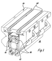
- FIGS. 1 to 10 each show a linear guide 10, which consists of a profile carrier 12 and a roller guide 14. Since the roller guide 14 and the profile carrier 12 of the linear guides 10 of the different embodiments each have the same functions, they are provided with the same reference numerals.
- FIG. 1 and 2 show the two basic possibilities of a relative movement between the profile carrier 12 and the roller guide 14.
- Roller guide 14 fixed and the profile carrier 12 is slidably mounted in the roller guide 14.
- the profile carrier 12 is arranged in a fixed manner and the roller guide 14 is slidably mounted on the profile carrier 12.
- Such linear guides 10 are required for a wide range of applications, for example as a guide for a robot arm, as a slide for a gripping device or the like. For this it is important that the moving masses are kept as small as possible and that they can be easily assembled.
- 12 grooves 16 are introduced into the profile carrier for this purpose.
- roller guide 14 is U-shaped in cross section in accordance with the embodiments shown in these figures and encompasses the profile carrier 12.
- the profile beams 12 shown in Figures 1 to 10 are each rectangular in cross section. However, they can equally well be circular, oval or correspondingly differently rounded in cross-section as a polygon.
- the roller guide 14 according to the embodiment of FIG. 3 has on its upper side two mutually parallel and undercut grooves 18 which are used in a known manner for fastening further components or machine parts.
- the roller carrier 14 has more than four over two each Ball bearing 20 rotatably mounted rollers 22 and 24 on the profile carrier 12.
- the axes of rotation of the rollers 22 and 24 shown in cross section are arranged in one plane and engage the profile carrier 12 in opposite directions. For this reason, the axes of rotation of the two rollers 22 and 24 are aligned in parallel.
- the rollers 22 and 24 are each provided with a pin 26 which engages in a bore in the roller guide 14 and which has a thread at its free end.
- a screw 28 is screwed onto the thread, so that the rollers 22, 24 are fastened in the roller guide 14 via the screw 28 and the pin 26 in cooperation with the bore of the roller guide 14.
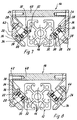
- the profile carrier 12 is rectangular in cross section and has a groove 16 on each side.
- the grooves 16 each form two outer surface regions 30 and 32 arranged at right angles to one another, namely a first outer surface region 30 and a second outer surface region 32.
- the transition between the first outer surface region 30 and the second outer surface region 32 is rounded.
- the rollers 22 and 24 each have an annular groove 34 with a first annular groove surface 36 and a second annular groove surface 38, which are aligned perpendicular to one another.
- the transition between the first annular groove surface 36 and the second annular groove surface 38 is also rounded.
- the rollers 22 and 24 engage diametrically opposite on the outer surface 30, 32 of the profile carrier 12. For this purpose, they are arranged in one plane and the central plane of the rollers 22 and 24, which is perpendicular to the axis of rotation, lies in the bisector of the angle between the first and the second outer surface regions 30 and 32 of the profile carrier 12.
- the grooves 16 are made in the center of the side surfaces of the rectangular profile carrier 12 and symmetrically and parallel to the longitudinal axis in the profile carrier 12.
- the first outer surface area 30 is arranged rectangularly with respect to the second outer surface area 32. Due to the rectangular arrangement of the first groove surface 36 with respect to the second groove surface 38, the rollers 22 and 24 are each adapted for contact with the mentioned outer surface regions 30 and 32. Since the two outer surface regions 30 and 32 are now arranged at right angles to one another on the one side and the median plane of the rollers 22 and 24 in the plane of the bisector and the annular groove 34 is adapted to the two outer surfaces 30 and 32 on the other side, the median plane lies of the rollers 22 and 24 at an angle of 45 ° to the first outer surface area 30 and to the second outer surface area 32, respectively.
- FIG. 5 shows two arrows X and Y, the arrow X running from left to right and the arrow Y running from top to bottom.
- the roller guide 14 is guided on the profile carrier 12 and / or vice versa.
- the outer surface areas 32 and the associated groove surfaces 38 thus form a guide corresponding to the direction of action of the arrow Y and the outer surface areas 30 and the associated groove surfaces 36 form a guide corresponding to the direction of action of the arrow X.
- roller guide 14 is thus fixed on the profile carrier 12 and can be moved along the profile carrier 12 by rolling the rollers 22 and 24. So that the roller guide 14 is securely arranged on the profile carrier 12, in addition to the rollers 22 and 24 in the longitudinal direction of the profile carrier 12 are offset - as mentioned above - further rollers 22 and 24 are arranged in the same manner as shown in FIG that the profile carrier 12 is mounted on a total of four rollers 22, 24. It should be clear that, depending on the design and stress of the roller guide 14, further rollers 22, 24 can also be provided in the roller guide 14.
- This arrangement has the advantage that the bearing forces acting in the X or Y direction always cause the same bearing stress on the rollers 22 and 24. This has the advantage that the system-specific load ratings of such linear guides 10 - regardless of the load application - are basically the same.
- FIG. 5 A further embodiment of the invention is shown in FIG.
- the profile carrier 12 now has two grooves 16 running in the longitudinal direction of the profile carrier 12 per side surface, as can be clearly seen from the cross-sectional illustration.
- this embodiment is constructed in accordance with the embodiment of FIG. 5. Only two grooves 16 per side surface and correspondingly more rollers 22, 24 are provided. Otherwise, the rollers 22 and 24 are aligned with one another, as in the embodiment in FIG. 5, and are designed and engage in a corresponding manner on the first and second outer surface regions 30 and 32.
- the axes of rotation of these rollers 22, 24 are all parallel, it should be clear that the rollers 22, 24 can also be arranged at a distance from one another with respect to the longitudinal axis.
- roller guide 14 is thus designed for greater loads than the roller guide 14 according to FIG. 5.
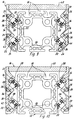
- FIGS. 7 and 8 show two sections through a further embodiment of a linear guide 10, the profile carrier 12 being designed in accordance with the embodiment of FIG. 5.
- the rollers 22 and 24 of the roller guide 14 act on two mutually distant sides of the rectangular profile carrier 12. Although the direction in which they engage the profile support 12 according to FIG. 7 or FIG. 8 is opposite to each other, the center plane of the rollers 22 and 24 is parallel to each other, but the rollers 22 and 24 are not in the same plane but are in relation to each other spaced apart.
- the correspondingly reversed arrangement of the rollers 22, 24 is shown in FIG. 7 and FIG. 8, respectively.
- the axes of rotation of the rollers 22 and 24 according to FIG. 7 on one side and FIG. 8 on the other side each lie in one plane, the figure 7 and FIG.
- roller guide 14 has eight rollers, namely two pairs of rollers according to FIG. 7 and two pairs of rollers according to FIG. 8.
- the rollers 20, 24 are formed and fastened in the roller guide 14.
- the roller guide 14 consists of a plate 40 and two side parts 42 and 44, to which the rollers 22 and 24 are screwed in each case.
- the side parts 42 and 44 are each screwed to the plate 40.
- FIGS. 9 and 10 Another embodiment of the invention is shown in FIGS. 9 and 10.
- the rollers 22 and 24 are arranged in accordance with the embodiment according to FIGS. 7 and 8, as follows from the following.
- the profile carrier 12 corresponds to the profile carrier 12 according to the embodiment of Figure 6 and thus points on each side two longitudinal grooves 16.
- FIG. 9 and FIG. 10 again show two adjacent cross sections through the linear guide 10, two rollers 22, 24 now acting on the profile carrier 12 in section on each side.
- the rollers 22 and 24 shown in section in FIGS. 9 and 10 are each arranged one below the other.
- the roller guide 14 is designed according to the embodiment of Figures 7 and 8.
- this embodiment has a total of sixteen rollers and eight pairs of rollers 22 and 24 as well as two arrangements each according to FIG. 9 and according to FIG. 10, the arrangements according to FIGS. 9 and 10 being provided in each case at the end regions of the roller guide 14.
- rollers 22 and 24 in the respective sectional views 9 and 10 is not mandatory. According to an alternative embodiment according to FIG. 9, the rollers 22, 24 can all be directed upwards or downwards, while the rollers 22 and 24 according to FIG. 10 can all be directed downwards or upwards. It is only necessary to ensure that the upwardly directed rollers 22 and 24 are opposed by correspondingly downwardly directed rollers 20 and 24 in order to guarantee unambiguous guidance of the roller guide 14 or the profile carrier 12.
- the profile carrier 12 shown in FIGS. 9 and 10 with the roller guide 14 and the arrangement of the rollers 22 and 24 can be designed in a variety of ways in accordance with the principle according to the invention. Depending on the requirement, additional grooves 16 can be introduced into the profile carrier 12 for the additional arrangement of rollers 22 and 24.
- rollers 22 and 24 are aligned at an angle of 45 ° to the first and / or second outer surface area 30, 32. In particular, this ensures that the linear guide 10, in particular the roller guide 14, is as small as possible. Judging from that Outside dimensions of the roller guide 14 and if the rollers 22, 24 were arranged perpendicular to the outer surface areas 30, 32 of the profile carrier 12, the dimensions of the roller guide 14 would increase per side surface by the factor root of 2 of the roller diameter. In addition to the same load cases when force is applied in different axial directions, the problem of ensuring the smallest possible design of the roller guide or the linear guide 10 with the optimal size of the rollers 22 and 24 is also solved.
Landscapes
- Engineering & Computer Science (AREA)
- General Engineering & Computer Science (AREA)
- Mechanical Engineering (AREA)
- Bearings For Parts Moving Linearly (AREA)
- Crystals, And After-Treatments Of Crystals (AREA)
- Magnetic Heads (AREA)
- Valve-Gear Or Valve Arrangements (AREA)
Applications Claiming Priority (2)
| Application Number | Priority Date | Filing Date | Title |
|---|---|---|---|
| DE4416459 | 1994-05-10 | ||
| DE4416459A DE4416459A1 (de) | 1994-05-10 | 1994-05-10 | Linearführung |
Publications (3)
| Publication Number | Publication Date |
|---|---|
| EP0686784A2 true EP0686784A2 (fr) | 1995-12-13 |
| EP0686784A3 EP0686784A3 (fr) | 1996-10-23 |
| EP0686784B1 EP0686784B1 (fr) | 2000-04-12 |
Family
ID=6517765
Family Applications (1)
| Application Number | Title | Priority Date | Filing Date |
|---|---|---|---|
| EP95102566A Expired - Lifetime EP0686784B1 (fr) | 1994-05-10 | 1995-02-23 | Palier linéaire |
Country Status (4)
| Country | Link |
|---|---|
| EP (1) | EP0686784B1 (fr) |
| AT (1) | ATE191774T1 (fr) |
| DE (2) | DE4416459A1 (fr) |
| ES (1) | ES2144535T3 (fr) |
Cited By (2)
| Publication number | Priority date | Publication date | Assignee | Title |
|---|---|---|---|---|
| EP2584209A1 (fr) * | 2011-10-17 | 2013-04-24 | NTN-SNR Roulements | Agencement de guidage linéaire |
| WO2013056728A1 (fr) * | 2011-10-17 | 2013-04-25 | Ntn-Snr Roulements | Structure de guidage linéaire |
Families Citing this family (2)
| Publication number | Priority date | Publication date | Assignee | Title |
|---|---|---|---|---|
| DE10108925B4 (de) * | 2001-02-23 | 2008-09-11 | Asm Automation Sensorik Messtechnik Gmbh | Magneto-striktive Wegmeß-Vorrichtung |
| IT1399329B1 (it) * | 2009-11-06 | 2013-04-16 | Manzoni | Monoblocco scorrevole di qualsiasi forma e funzione con elementi di movimentazione comunque invisibili, essendo sia la pista di scorrimento, solidale al monoblocco, che il carrello portante, ancorato a pavimento o a soffitto o a parete, che il carrello direzionale, inglobati nel monoblocco stesso. |
Citations (2)
| Publication number | Priority date | Publication date | Assignee | Title |
|---|---|---|---|---|
| FR2545030A1 (fr) * | 1983-04-27 | 1984-11-02 | Telemecanique Electrique | Manipulateur a colonne mobile a guidage ameliore dans un corps fixe |
| US4944608A (en) * | 1988-03-28 | 1990-07-31 | Nippon Seiko Kabushiki Kaisha | Roller-type linear guide |
-
1994
- 1994-05-10 DE DE4416459A patent/DE4416459A1/de not_active Withdrawn
-
1995
- 1995-02-23 ES ES95102566T patent/ES2144535T3/es not_active Expired - Lifetime
- 1995-02-23 AT AT95102566T patent/ATE191774T1/de not_active IP Right Cessation
- 1995-02-23 DE DE59508158T patent/DE59508158D1/de not_active Expired - Lifetime
- 1995-02-23 EP EP95102566A patent/EP0686784B1/fr not_active Expired - Lifetime
Patent Citations (2)
| Publication number | Priority date | Publication date | Assignee | Title |
|---|---|---|---|---|
| FR2545030A1 (fr) * | 1983-04-27 | 1984-11-02 | Telemecanique Electrique | Manipulateur a colonne mobile a guidage ameliore dans un corps fixe |
| US4944608A (en) * | 1988-03-28 | 1990-07-31 | Nippon Seiko Kabushiki Kaisha | Roller-type linear guide |
Cited By (2)
| Publication number | Priority date | Publication date | Assignee | Title |
|---|---|---|---|---|
| EP2584209A1 (fr) * | 2011-10-17 | 2013-04-24 | NTN-SNR Roulements | Agencement de guidage linéaire |
| WO2013056728A1 (fr) * | 2011-10-17 | 2013-04-25 | Ntn-Snr Roulements | Structure de guidage linéaire |
Also Published As
| Publication number | Publication date |
|---|---|
| ES2144535T3 (es) | 2000-06-16 |
| EP0686784B1 (fr) | 2000-04-12 |
| DE59508158D1 (de) | 2000-05-18 |
| ATE191774T1 (de) | 2000-04-15 |
| DE4416459A1 (de) | 1995-11-16 |
| EP0686784A3 (fr) | 1996-10-23 |
Similar Documents
| Publication | Publication Date | Title |
|---|---|---|
| DE3627169C2 (de) | Lineare Wälzkörperführung | |
| DE2945594C2 (de) | Linearlager mit vier Kugelumläufen | |
| DE2743835C2 (de) | Vorrichtung zum Verschieben eines Oberteiles parallel zu einem festen Unterteil mittels einer Kreuzführung | |
| EP0422419B1 (fr) | Palier à roulement pour mouvements linéaires avec réglage de la précontrainte dans le dispositif de guidage | |
| DE69314294T2 (de) | Gleitstellglied | |
| DE3303831C2 (fr) | ||
| DE69127252T2 (de) | Linearlager | |
| DE2829433C2 (de) | Schraubengetriebe | |
| DE3607592A1 (de) | Linearrollenlager | |
| DE69313708T2 (de) | Führungseinheit für geradlinige Wälzbewegung | |
| EP0577963B1 (fr) | Guide linéaire | |
| DE8631316U1 (de) | Hängerollwand | |
| DE3347869C2 (fr) | ||
| DE3134313C2 (de) | Wälzlager für lineare Bewegung | |
| DE69119373T2 (de) | Tisch für linearführung | |
| DE202017004877U1 (de) | Parallelgreifer mit biaxialer Stützstruktur | |
| DE1813800A1 (de) | Flexibles Steuerkabel | |
| DE3508604C2 (fr) | ||
| DE3905566C1 (de) | Gleichlaufgelenk mit axial gegeneinander verschiebbaren Gelenkteilen | |
| DE3012765C2 (fr) | ||
| DE9315178U1 (de) | Linearführung | |
| DE19619449A1 (de) | Linearführung | |
| EP0686784A2 (fr) | Palier linéaire | |
| DE3709039C2 (de) | Käfig für Längsbewegungen ausführende Rollenlager | |
| DE4133310A1 (de) | Waelzlager-geradefuehrungseinheit mit vier endlosen waelzlagerelement-umlaufwegen |
Legal Events
| Date | Code | Title | Description |
|---|---|---|---|
| PUAI | Public reference made under article 153(3) epc to a published international application that has entered the european phase |
Free format text: ORIGINAL CODE: 0009012 |
|
| AK | Designated contracting states |
Kind code of ref document: A2 Designated state(s): AT BE DE ES FR GB IT LU |
|
| PUAL | Search report despatched |
Free format text: ORIGINAL CODE: 0009013 |
|
| AK | Designated contracting states |
Kind code of ref document: A3 Designated state(s): AT BE DE ES FR GB IT LU |
|
| 17P | Request for examination filed |
Effective date: 19961125 |
|
| 17Q | First examination report despatched |
Effective date: 19980630 |
|
| GRAG | Despatch of communication of intention to grant |
Free format text: ORIGINAL CODE: EPIDOS AGRA |
|
| GRAG | Despatch of communication of intention to grant |
Free format text: ORIGINAL CODE: EPIDOS AGRA |
|
| GRAH | Despatch of communication of intention to grant a patent |
Free format text: ORIGINAL CODE: EPIDOS IGRA |
|
| ITF | It: translation for a ep patent filed | ||
| GRAH | Despatch of communication of intention to grant a patent |
Free format text: ORIGINAL CODE: EPIDOS IGRA |
|
| GRAA | (expected) grant |
Free format text: ORIGINAL CODE: 0009210 |
|
| AK | Designated contracting states |
Kind code of ref document: B1 Designated state(s): AT BE DE ES FR GB IT LU |
|
| REF | Corresponds to: |
Ref document number: 191774 Country of ref document: AT Date of ref document: 20000415 Kind code of ref document: T |
|
| REF | Corresponds to: |
Ref document number: 59508158 Country of ref document: DE Date of ref document: 20000518 |
|
| GBT | Gb: translation of ep patent filed (gb section 77(6)(a)/1977) |
Effective date: 20000519 |
|
| REG | Reference to a national code |
Ref country code: ES Ref legal event code: FG2A Ref document number: 2144535 Country of ref document: ES Kind code of ref document: T3 |
|
| ET | Fr: translation filed | ||
| PLBE | No opposition filed within time limit |
Free format text: ORIGINAL CODE: 0009261 |
|
| STAA | Information on the status of an ep patent application or granted ep patent |
Free format text: STATUS: NO OPPOSITION FILED WITHIN TIME LIMIT |
|
| 26N | No opposition filed | ||
| REG | Reference to a national code |
Ref country code: GB Ref legal event code: IF02 |
|
| PGFP | Annual fee paid to national office [announced via postgrant information from national office to epo] |
Ref country code: LU Payment date: 20090224 Year of fee payment: 15 Ref country code: ES Payment date: 20090225 Year of fee payment: 15 Ref country code: AT Payment date: 20090219 Year of fee payment: 15 |
|
| PGFP | Annual fee paid to national office [announced via postgrant information from national office to epo] |
Ref country code: GB Payment date: 20090223 Year of fee payment: 15 |
|
| PGFP | Annual fee paid to national office [announced via postgrant information from national office to epo] |
Ref country code: BE Payment date: 20090224 Year of fee payment: 15 |
|
| PGFP | Annual fee paid to national office [announced via postgrant information from national office to epo] |
Ref country code: IT Payment date: 20090227 Year of fee payment: 15 |
|
| PGFP | Annual fee paid to national office [announced via postgrant information from national office to epo] |
Ref country code: FR Payment date: 20090217 Year of fee payment: 15 |
|
| PGFP | Annual fee paid to national office [announced via postgrant information from national office to epo] |
Ref country code: DE Payment date: 20100302 Year of fee payment: 16 |
|
| BERE | Be: lapsed |
Owner name: *SCHUCO INTERNATIONAL K.G. Effective date: 20100228 |
|
| GBPC | Gb: european patent ceased through non-payment of renewal fee |
Effective date: 20100223 |
|
| REG | Reference to a national code |
Ref country code: FR Ref legal event code: ST Effective date: 20101029 |
|
| PG25 | Lapsed in a contracting state [announced via postgrant information from national office to epo] |
Ref country code: AT Free format text: LAPSE BECAUSE OF NON-PAYMENT OF DUE FEES Effective date: 20100223 |
|
| PG25 | Lapsed in a contracting state [announced via postgrant information from national office to epo] |
Ref country code: FR Free format text: LAPSE BECAUSE OF NON-PAYMENT OF DUE FEES Effective date: 20100301 |
|
| PG25 | Lapsed in a contracting state [announced via postgrant information from national office to epo] |
Ref country code: BE Free format text: LAPSE BECAUSE OF NON-PAYMENT OF DUE FEES Effective date: 20100228 |
|
| REG | Reference to a national code |
Ref country code: ES Ref legal event code: FD2A Effective date: 20110310 |
|
| PG25 | Lapsed in a contracting state [announced via postgrant information from national office to epo] |
Ref country code: IT Free format text: LAPSE BECAUSE OF NON-PAYMENT OF DUE FEES Effective date: 20100223 Ref country code: GB Free format text: LAPSE BECAUSE OF NON-PAYMENT OF DUE FEES Effective date: 20100223 |
|
| PG25 | Lapsed in a contracting state [announced via postgrant information from national office to epo] |
Ref country code: ES Free format text: LAPSE BECAUSE OF NON-PAYMENT OF DUE FEES Effective date: 20110309 |
|
| PG25 | Lapsed in a contracting state [announced via postgrant information from national office to epo] |
Ref country code: ES Free format text: LAPSE BECAUSE OF NON-PAYMENT OF DUE FEES Effective date: 20100224 |
|
| REG | Reference to a national code |
Ref country code: DE Ref legal event code: R119 Ref document number: 59508158 Country of ref document: DE Effective date: 20110901 |
|
| PG25 | Lapsed in a contracting state [announced via postgrant information from national office to epo] |
Ref country code: LU Free format text: LAPSE BECAUSE OF NON-PAYMENT OF DUE FEES Effective date: 20100223 |
|
| PG25 | Lapsed in a contracting state [announced via postgrant information from national office to epo] |
Ref country code: DE Free format text: LAPSE BECAUSE OF NON-PAYMENT OF DUE FEES Effective date: 20110901 |