EP0686784A2 - Linear guide - Google Patents
Linear guide Download PDFInfo
- Publication number
- EP0686784A2 EP0686784A2 EP95102566A EP95102566A EP0686784A2 EP 0686784 A2 EP0686784 A2 EP 0686784A2 EP 95102566 A EP95102566 A EP 95102566A EP 95102566 A EP95102566 A EP 95102566A EP 0686784 A2 EP0686784 A2 EP 0686784A2
- Authority
- EP
- European Patent Office
- Prior art keywords
- rollers
- profile carrier
- linear guide
- guide according
- roller
- Prior art date
- Legal status (The legal status is an assumption and is not a legal conclusion. Google has not performed a legal analysis and makes no representation as to the accuracy of the status listed.)
- Granted
Links
Images


Classifications
-
- F—MECHANICAL ENGINEERING; LIGHTING; HEATING; WEAPONS; BLASTING
- F16—ENGINEERING ELEMENTS AND UNITS; GENERAL MEASURES FOR PRODUCING AND MAINTAINING EFFECTIVE FUNCTIONING OF MACHINES OR INSTALLATIONS; THERMAL INSULATION IN GENERAL
- F16C—SHAFTS; FLEXIBLE SHAFTS; ELEMENTS OR CRANKSHAFT MECHANISMS; ROTARY BODIES OTHER THAN GEARING ELEMENTS; BEARINGS
- F16C29/00—Bearings for parts moving only linearly
- F16C29/04—Ball or roller bearings
- F16C29/048—Ball or roller bearings with thin walled races, e.g. tracks of sheet metal
-
- B—PERFORMING OPERATIONS; TRANSPORTING
- B23—MACHINE TOOLS; METAL-WORKING NOT OTHERWISE PROVIDED FOR
- B23Q—DETAILS, COMPONENTS, OR ACCESSORIES FOR MACHINE TOOLS, e.g. ARRANGEMENTS FOR COPYING OR CONTROLLING; MACHINE TOOLS IN GENERAL CHARACTERISED BY THE CONSTRUCTION OF PARTICULAR DETAILS OR COMPONENTS; COMBINATIONS OR ASSOCIATIONS OF METAL-WORKING MACHINES, NOT DIRECTED TO A PARTICULAR RESULT
- B23Q1/00—Members which are comprised in the general build-up of a form of machine, particularly relatively large fixed members
- B23Q1/25—Movable or adjustable work or tool supports
- B23Q1/26—Movable or adjustable work or tool supports characterised by constructional features relating to the co-operation of relatively movable members; Means for preventing relative movement of such members
- B23Q1/40—Movable or adjustable work or tool supports characterised by constructional features relating to the co-operation of relatively movable members; Means for preventing relative movement of such members using ball, roller or wheel arrangements
-
- B—PERFORMING OPERATIONS; TRANSPORTING
- B23—MACHINE TOOLS; METAL-WORKING NOT OTHERWISE PROVIDED FOR
- B23Q—DETAILS, COMPONENTS, OR ACCESSORIES FOR MACHINE TOOLS, e.g. ARRANGEMENTS FOR COPYING OR CONTROLLING; MACHINE TOOLS IN GENERAL CHARACTERISED BY THE CONSTRUCTION OF PARTICULAR DETAILS OR COMPONENTS; COMBINATIONS OR ASSOCIATIONS OF METAL-WORKING MACHINES, NOT DIRECTED TO A PARTICULAR RESULT
- B23Q1/00—Members which are comprised in the general build-up of a form of machine, particularly relatively large fixed members
- B23Q1/25—Movable or adjustable work or tool supports
- B23Q1/44—Movable or adjustable work or tool supports using particular mechanisms
- B23Q1/56—Movable or adjustable work or tool supports using particular mechanisms with sliding pairs only, the sliding pairs being the first two elements of the mechanism
- B23Q1/58—Movable or adjustable work or tool supports using particular mechanisms with sliding pairs only, the sliding pairs being the first two elements of the mechanism a single sliding pair
-
- F—MECHANICAL ENGINEERING; LIGHTING; HEATING; WEAPONS; BLASTING
- F16—ENGINEERING ELEMENTS AND UNITS; GENERAL MEASURES FOR PRODUCING AND MAINTAINING EFFECTIVE FUNCTIONING OF MACHINES OR INSTALLATIONS; THERMAL INSULATION IN GENERAL
- F16C—SHAFTS; FLEXIBLE SHAFTS; ELEMENTS OR CRANKSHAFT MECHANISMS; ROTARY BODIES OTHER THAN GEARING ELEMENTS; BEARINGS
- F16C29/00—Bearings for parts moving only linearly
- F16C29/04—Ball or roller bearings
- F16C29/045—Ball or roller bearings having rolling elements journaled in one of the moving parts
-
- F—MECHANICAL ENGINEERING; LIGHTING; HEATING; WEAPONS; BLASTING
- F16—ENGINEERING ELEMENTS AND UNITS; GENERAL MEASURES FOR PRODUCING AND MAINTAINING EFFECTIVE FUNCTIONING OF MACHINES OR INSTALLATIONS; THERMAL INSULATION IN GENERAL
- F16C—SHAFTS; FLEXIBLE SHAFTS; ELEMENTS OR CRANKSHAFT MECHANISMS; ROTARY BODIES OTHER THAN GEARING ELEMENTS; BEARINGS
- F16C2322/00—Apparatus used in shaping articles
- F16C2322/39—General build up of machine tools, e.g. spindles, slides, actuators
Definitions
- the invention relates to a linear guide according to the type specified in the preamble of claim 1.
- Linear guides of this type are known in different embodiments and are provided with a profile carrier which has certain outer surface areas arranged at an angle to one another and with a roller guide which engages the profile carrier via rollers.
- the profile carrier has grooves on its outside, via which the profile carrier can be attached to other components of a module system.
- the roller guide is designed as a slide with rollers engaging in grooves of the profile carrier, the slide being movable relative to the profile carrier.
- the grooves of the profile carrier, in which the rollers of the slide engage are U-shaped in cross section. The two U-shaped legs rest on diametrically opposite sides of the rollers, as a result of which the slide is mounted in a linearly displaceable manner in the profile carrier.
- the slide essentially engages in the profile carrier and has a corresponding recess for this.
- This linear guide has the disadvantage that the profile carrier is custom-made, which not only has to have precise machining with regard to the accuracy of the outer grooves, but also has to meet considerable tolerance requirements or accuracy requirements, in particular, with regard to the design of the interior of the recess for the slide because the interior of the direct Sled guide is used.
- the profile carrier is also open on one side through the recess so that the slide can be guided in the interior. For this reason, the profile beam can only be loaded to a limited extent and can therefore only be used to a limited extent.
- Another known linear guide also has a profile carrier with grooves, in which round guides are introduced via fastening parts.
- These circular guides serve as rails for rollers of the roller guide which are adapted to the circular guides.
- large diameters of the rollers are required.
- the running quality as well as the load transmission is dependent on the diameter of the rollers, since this can influence Hertzian pressure. Accordingly, the larger a roller is designed, the more favorable it is with regard to its running properties.
- this embodiment has the disadvantage that additional parts are required for the roller guide. Furthermore, the arrangement of the rollers perpendicular to one side of the rectangular profile support results in a relatively large construction dimension.
- the invention has for its object to develop a linear guide according to the type specified in the preamble of claim 1 such that there is a simple construction and arrangement of the roller guide and a correspondingly smaller size.
- a roller is adapted to and rests against a first and a second outer surface area of the profile carrier, the first and second outer surface areas being adjacent to one another and arranged at an angle to one another. This ensures that the roller cannot migrate laterally and the bearing forces can be transferred to the roller and vice versa both via the first and the second outer surface area.
- rollers In order to enable a uniform loading of the rollers, all rollers are each adapted to a first and second outer surface area and rest on it in the same way. Each role is used to guide the profile beam and migration of the individual roles is not possible.
- the roller has an annular groove which is provided with two groove surfaces arranged at an angle to one another, a first groove surface bearing against the first outer surface region and a second groove surface resting against the second outer surface region of the profile carrier.
- the profile carrier has a corresponding groove and the roller has a shape adapted to the groove with surfaces oriented at an angle to one another.
- the possibilities of contact of the rollers on the profile carrier and the contact surface can in particular be increased in that grooves in the profile carrier form the first and / or second outer surface area.
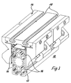
- FIGS. 1 to 10 each show a linear guide 10, which consists of a profile carrier 12 and a roller guide 14. Since the roller guide 14 and the profile carrier 12 of the linear guides 10 of the different embodiments each have the same functions, they are provided with the same reference numerals.
- FIG. 1 and 2 show the two basic possibilities of a relative movement between the profile carrier 12 and the roller guide 14.
- Roller guide 14 fixed and the profile carrier 12 is slidably mounted in the roller guide 14.
- the profile carrier 12 is arranged in a fixed manner and the roller guide 14 is slidably mounted on the profile carrier 12.
- Such linear guides 10 are required for a wide range of applications, for example as a guide for a robot arm, as a slide for a gripping device or the like. For this it is important that the moving masses are kept as small as possible and that they can be easily assembled.
- 12 grooves 16 are introduced into the profile carrier for this purpose.
- roller guide 14 is U-shaped in cross section in accordance with the embodiments shown in these figures and encompasses the profile carrier 12.
- the profile beams 12 shown in Figures 1 to 10 are each rectangular in cross section. However, they can equally well be circular, oval or correspondingly differently rounded in cross-section as a polygon.
- the roller guide 14 according to the embodiment of FIG. 3 has on its upper side two mutually parallel and undercut grooves 18 which are used in a known manner for fastening further components or machine parts.
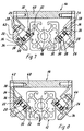
- the roller carrier 14 has more than four over two each Ball bearing 20 rotatably mounted rollers 22 and 24 on the profile carrier 12.
- the axes of rotation of the rollers 22 and 24 shown in cross section are arranged in one plane and engage the profile carrier 12 in opposite directions. For this reason, the axes of rotation of the two rollers 22 and 24 are aligned in parallel.
- the rollers 22 and 24 are each provided with a pin 26 which engages in a bore in the roller guide 14 and which has a thread at its free end.
- a screw 28 is screwed onto the thread, so that the rollers 22, 24 are fastened in the roller guide 14 via the screw 28 and the pin 26 in cooperation with the bore of the roller guide 14.
- the profile carrier 12 is rectangular in cross section and has a groove 16 on each side.
- the grooves 16 each form two outer surface regions 30 and 32 arranged at right angles to one another, namely a first outer surface region 30 and a second outer surface region 32.
- the transition between the first outer surface region 30 and the second outer surface region 32 is rounded.
- the rollers 22 and 24 each have an annular groove 34 with a first annular groove surface 36 and a second annular groove surface 38, which are aligned perpendicular to one another.
- the transition between the first annular groove surface 36 and the second annular groove surface 38 is also rounded.
- the rollers 22 and 24 engage diametrically opposite on the outer surface 30, 32 of the profile carrier 12. For this purpose, they are arranged in one plane and the central plane of the rollers 22 and 24, which is perpendicular to the axis of rotation, lies in the bisector of the angle between the first and the second outer surface regions 30 and 32 of the profile carrier 12.
- the grooves 16 are made in the center of the side surfaces of the rectangular profile carrier 12 and symmetrically and parallel to the longitudinal axis in the profile carrier 12.
- the first outer surface area 30 is arranged rectangularly with respect to the second outer surface area 32. Due to the rectangular arrangement of the first groove surface 36 with respect to the second groove surface 38, the rollers 22 and 24 are each adapted for contact with the mentioned outer surface regions 30 and 32. Since the two outer surface regions 30 and 32 are now arranged at right angles to one another on the one side and the median plane of the rollers 22 and 24 in the plane of the bisector and the annular groove 34 is adapted to the two outer surfaces 30 and 32 on the other side, the median plane lies of the rollers 22 and 24 at an angle of 45 ° to the first outer surface area 30 and to the second outer surface area 32, respectively.
- FIG. 5 shows two arrows X and Y, the arrow X running from left to right and the arrow Y running from top to bottom.
- the roller guide 14 is guided on the profile carrier 12 and / or vice versa.
- the outer surface areas 32 and the associated groove surfaces 38 thus form a guide corresponding to the direction of action of the arrow Y and the outer surface areas 30 and the associated groove surfaces 36 form a guide corresponding to the direction of action of the arrow X.
- roller guide 14 is thus fixed on the profile carrier 12 and can be moved along the profile carrier 12 by rolling the rollers 22 and 24. So that the roller guide 14 is securely arranged on the profile carrier 12, in addition to the rollers 22 and 24 in the longitudinal direction of the profile carrier 12 are offset - as mentioned above - further rollers 22 and 24 are arranged in the same manner as shown in FIG that the profile carrier 12 is mounted on a total of four rollers 22, 24. It should be clear that, depending on the design and stress of the roller guide 14, further rollers 22, 24 can also be provided in the roller guide 14.
- This arrangement has the advantage that the bearing forces acting in the X or Y direction always cause the same bearing stress on the rollers 22 and 24. This has the advantage that the system-specific load ratings of such linear guides 10 - regardless of the load application - are basically the same.
- FIG. 5 A further embodiment of the invention is shown in FIG.
- the profile carrier 12 now has two grooves 16 running in the longitudinal direction of the profile carrier 12 per side surface, as can be clearly seen from the cross-sectional illustration.
- this embodiment is constructed in accordance with the embodiment of FIG. 5. Only two grooves 16 per side surface and correspondingly more rollers 22, 24 are provided. Otherwise, the rollers 22 and 24 are aligned with one another, as in the embodiment in FIG. 5, and are designed and engage in a corresponding manner on the first and second outer surface regions 30 and 32.
- the axes of rotation of these rollers 22, 24 are all parallel, it should be clear that the rollers 22, 24 can also be arranged at a distance from one another with respect to the longitudinal axis.
- roller guide 14 is thus designed for greater loads than the roller guide 14 according to FIG. 5.
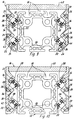
- FIGS. 7 and 8 show two sections through a further embodiment of a linear guide 10, the profile carrier 12 being designed in accordance with the embodiment of FIG. 5.
- the rollers 22 and 24 of the roller guide 14 act on two mutually distant sides of the rectangular profile carrier 12. Although the direction in which they engage the profile support 12 according to FIG. 7 or FIG. 8 is opposite to each other, the center plane of the rollers 22 and 24 is parallel to each other, but the rollers 22 and 24 are not in the same plane but are in relation to each other spaced apart.
- the correspondingly reversed arrangement of the rollers 22, 24 is shown in FIG. 7 and FIG. 8, respectively.
- the axes of rotation of the rollers 22 and 24 according to FIG. 7 on one side and FIG. 8 on the other side each lie in one plane, the figure 7 and FIG.
- roller guide 14 has eight rollers, namely two pairs of rollers according to FIG. 7 and two pairs of rollers according to FIG. 8.
- the rollers 20, 24 are formed and fastened in the roller guide 14.
- the roller guide 14 consists of a plate 40 and two side parts 42 and 44, to which the rollers 22 and 24 are screwed in each case.
- the side parts 42 and 44 are each screwed to the plate 40.
- FIGS. 9 and 10 Another embodiment of the invention is shown in FIGS. 9 and 10.
- the rollers 22 and 24 are arranged in accordance with the embodiment according to FIGS. 7 and 8, as follows from the following.
- the profile carrier 12 corresponds to the profile carrier 12 according to the embodiment of Figure 6 and thus points on each side two longitudinal grooves 16.
- FIG. 9 and FIG. 10 again show two adjacent cross sections through the linear guide 10, two rollers 22, 24 now acting on the profile carrier 12 in section on each side.
- the rollers 22 and 24 shown in section in FIGS. 9 and 10 are each arranged one below the other.
- the roller guide 14 is designed according to the embodiment of Figures 7 and 8.
- this embodiment has a total of sixteen rollers and eight pairs of rollers 22 and 24 as well as two arrangements each according to FIG. 9 and according to FIG. 10, the arrangements according to FIGS. 9 and 10 being provided in each case at the end regions of the roller guide 14.
- rollers 22 and 24 in the respective sectional views 9 and 10 is not mandatory. According to an alternative embodiment according to FIG. 9, the rollers 22, 24 can all be directed upwards or downwards, while the rollers 22 and 24 according to FIG. 10 can all be directed downwards or upwards. It is only necessary to ensure that the upwardly directed rollers 22 and 24 are opposed by correspondingly downwardly directed rollers 20 and 24 in order to guarantee unambiguous guidance of the roller guide 14 or the profile carrier 12.
- the profile carrier 12 shown in FIGS. 9 and 10 with the roller guide 14 and the arrangement of the rollers 22 and 24 can be designed in a variety of ways in accordance with the principle according to the invention. Depending on the requirement, additional grooves 16 can be introduced into the profile carrier 12 for the additional arrangement of rollers 22 and 24.
- rollers 22 and 24 are aligned at an angle of 45 ° to the first and / or second outer surface area 30, 32. In particular, this ensures that the linear guide 10, in particular the roller guide 14, is as small as possible. Judging from that Outside dimensions of the roller guide 14 and if the rollers 22, 24 were arranged perpendicular to the outer surface areas 30, 32 of the profile carrier 12, the dimensions of the roller guide 14 would increase per side surface by the factor root of 2 of the roller diameter. In addition to the same load cases when force is applied in different axial directions, the problem of ensuring the smallest possible design of the roller guide or the linear guide 10 with the optimal size of the rollers 22 and 24 is also solved.
Abstract
Description
Die Erfindung betrifft eine Linearführung gemäß der im Oberbegriff des Anspruches 1 angegebenen Art.The invention relates to a linear guide according to the type specified in the preamble of claim 1.
Derartige Linearführungen sind in unterschiedlichen Ausführungsformen bekannt und mit einem Profilträger, der bestimmte, im Winkel zueinander angeordnete Außenflächenbereiche aufweist, und mit einer an den Profilträger über Rollen angreifenden Rollenführung versehen. Der Profilträger weist an seiner Außenseite Nuten auf, über die der Profilträger an weitere Komponenten eines Modulsystems befestigt werden kann. Die Rollenführung ist als Schlitten mit in Nuten des Profilträgers eingreifenden Rollen ausgebildet, wobei der Schlitten relativ gegenüber dem Profilträger verfahrbar ist. Die Nuten des Profilträgers, in die die Rollen des Schlittens eingreifen, sind im Querschnitt U-förmig ausführt. Die beiden U-förmigen Schenkel liegen an diametral gegenüberliegenden Seiten der Rollen an, wodurch der Schlitten in dem Profilträger linear verschiebbar gelagert ist. Der Schlitten greift gemäß dieser Ausführung im wesentlichen in den Profilträger ein und weist dafür eine entsprechende Ausnehmung auf.Linear guides of this type are known in different embodiments and are provided with a profile carrier which has certain outer surface areas arranged at an angle to one another and with a roller guide which engages the profile carrier via rollers. The profile carrier has grooves on its outside, via which the profile carrier can be attached to other components of a module system. The roller guide is designed as a slide with rollers engaging in grooves of the profile carrier, the slide being movable relative to the profile carrier. The grooves of the profile carrier, in which the rollers of the slide engage, are U-shaped in cross section. The two U-shaped legs rest on diametrically opposite sides of the rollers, as a result of which the slide is mounted in a linearly displaceable manner in the profile carrier. According to this embodiment, the slide essentially engages in the profile carrier and has a corresponding recess for this.
Diese Linearführung hat den Nachteil, daß der Profilträger eine Spezialanfertigung ist, der nicht nur eine exakte Bearbeitung hinsichtlich der Genauigkeit der äußeren Nuten aufweisen muß, sondern auch hinsichtlich der Gestaltung des Innenraumes der Ausnehmung für den Schlitten erheblichen Toleranzanforderungen bzw. Genauigkeitsanforderungen gerecht werden muß, insbesondere da der Innenraum der direkten Schlittenführung dient. Darüber hinaus besteht eine direkte Größenabhängigkeit des Profilträgers für die unterschiedlichen Leistungsanforderungen an die Linearführung. Der Profilträger ist desweiteren durch die Ausnehmung einseitig geöffnet, damit der Schlitten in dem Innenraum geführt werden kann. Aus diesem Grunde ist der Profilträger nur beschränkt belastbar und damit nur im beschränkten Umfang einsetzbar..This linear guide has the disadvantage that the profile carrier is custom-made, which not only has to have precise machining with regard to the accuracy of the outer grooves, but also has to meet considerable tolerance requirements or accuracy requirements, in particular, with regard to the design of the interior of the recess for the slide because the interior of the direct Sled guide is used. In addition, there is a direct size dependency of the profile carrier for the different performance requirements for the linear guide. The profile carrier is also open on one side through the recess so that the slide can be guided in the interior. For this reason, the profile beam can only be loaded to a limited extent and can therefore only be used to a limited extent.
Eine weitere bekannte Linearführung weist ebenfalls einen Profilträger mit Nuten auf, in die über Befestigungsteile Rundführungen eingebracht sind. Diese Rundführungen dienen als Schienen für an die Rundführungen angepaßte Rollen der Rollenführung. Um ein möglichst ruhiges Verfahren der Rollenführung zu erzielen und insbesondere um entsprechend hohe Kräfte übertragen zu können, sind große Durchmesser der Laufrollen erforderlich. Die Laufgüte als auch die Lastübertragung ist nämlich von dem Durchmesser der Rollen abhängig, da sich dadurch die Hertz'sche Pressung beeinflussen läßt. Je größer demnach eine Rolle ausgebildet ist, um so günstiger verhält sich diese bezüglich ihrer Laufeigenschaften.Another known linear guide also has a profile carrier with grooves, in which round guides are introduced via fastening parts. These circular guides serve as rails for rollers of the roller guide which are adapted to the circular guides. In order to achieve the smoothest possible movement of the roller guide and in particular to be able to transmit correspondingly high forces, large diameters of the rollers are required. The running quality as well as the load transmission is dependent on the diameter of the rollers, since this can influence Hertzian pressure. Accordingly, the larger a roller is designed, the more favorable it is with regard to its running properties.
Diese Ausführung hat jedoch den Nachteil, daß zusätzliche Teile für die Rollenführung notwendig sind. Desweiteren ergibt sich durch die Anordnung der Rollen senkrecht zu einer Seite des rechteckigen Profilträgers ein relativ großes Baumaß.However, this embodiment has the disadvantage that additional parts are required for the roller guide. Furthermore, the arrangement of the rollers perpendicular to one side of the rectangular profile support results in a relatively large construction dimension.
Der Erfindung liegt die Aufgabe zugrunde, eine Linearführung gemäß der im Oberbegriff des Anspruches 1 angegebenen Art derart weiterzubilden, daß sich eine einfache Konstruktion und Anordnung der Rollenführung als auch ein entsprechend geringeres Baumaß ergibt.The invention has for its object to develop a linear guide according to the type specified in the preamble of claim 1 such that there is a simple construction and arrangement of the roller guide and a correspondingly smaller size.
Diese Aufgabe wird durch die kennzeichnenden Merkmale des Anspruches 1 in Verbindung mit seinen Oberbegriffsmerkmalen gelöst. Nunmehr liegen die Rollen unmittelbar an dem Profilträger an, so daß sich gegenüber den bekannten Linearführungen eine Gewichtsersparnis ergibt. Weiterhin ist eine Rolle an einen ersten und einen zweiten Außenflächenbereich des Profilträgers angepaßt und liegt daran an, wobei der erste und zweite Außenflächenbereich zueinander benachbart und zueinander im Winkel angeordnet sind. Dadurch wird gewährleistet, daß die Rolle nicht seitlich auswandern kann und die Lagerkräfte sowohl über den ersten als auch über den zweiten Außenflächenbereich auf die Rolle und umgekehrt übertragen werden können.This object is achieved by the characterizing features of claim 1 in connection with its preamble features. Now the roles are directly on the Profile carrier so that there is a weight saving compared to the known linear guides. Furthermore, a roller is adapted to and rests against a first and a second outer surface area of the profile carrier, the first and second outer surface areas being adjacent to one another and arranged at an angle to one another. This ensures that the roller cannot migrate laterally and the bearing forces can be transferred to the roller and vice versa both via the first and the second outer surface area.
Um eine gleichmäßige Belastung der Rollen zu ermöglichen, sind alle Rollen jeweils an einen ersten und zweiten Außenflächenbereich angepaßt und liegen daran in derselben Art und Weise an. Jede Rolle dient also der Führung des Profilträgers und ein Auswandern der einzelnen Rollen ist nicht möglich.In order to enable a uniform loading of the rollers, all rollers are each adapted to a first and second outer surface area and rest on it in the same way. Each role is used to guide the profile beam and migration of the individual roles is not possible.
Gemäß einer Ausführungsform weist die Rolle eine mit zwei im Winkel zueinander angeordnete Nutflächen versehene Ringnut auf, wobei eine erste Nutfläche an dem ersten Außenflächenbereich und eine zweite Nutfläche an dem zweiten Außenflächenbereich des Profilträgers anliegt. Grundsätzlich ist aber auch eine entsprechend umgekehrte Ausbildung möglich, bei der der Profilträger eine entsprechende Nut und die Rolle eine an die Nut angepaßte Ausformung mit im Winkel zueinander ausgerichteten Flächen aufweist.According to one embodiment, the roller has an annular groove which is provided with two groove surfaces arranged at an angle to one another, a first groove surface bearing against the first outer surface region and a second groove surface resting against the second outer surface region of the profile carrier. In principle, however, a correspondingly reversed design is also possible, in which the profile carrier has a corresponding groove and the roller has a shape adapted to the groove with surfaces oriented at an angle to one another.
Die Anlagemöglichkeiten der Rollen an dem Profilträger sowie die Anlagefläche können insbesondere dadurch vergrößert werden, daß Nuten in dem Profilträger den ersten und/oder zweiten Außenflächenbereich bilden.The possibilities of contact of the rollers on the profile carrier and the contact surface can in particular be increased in that grooves in the profile carrier form the first and / or second outer surface area.
Weitere Merkmale bilden die Gegenstände der anderen Unteransprüche.Other features form the subject of the other subclaims.
Zusätzliche Vorteile und Merkmale ergeben sich aber auch aus der folgenden Beschreibung mehrerer Ausführungsformen der Erfindung im Zusammenhang mit der Zeichnung. Es zeigen:
- Figur 1 und 2
- jeweils eine prinzipielle Darstellung einer Linearführung mit Rollenführung und Profilträger;
- Figur 3
- eine perspektivische Darstellung einer Linearführung gemäß einer ersten Ausführungsform;
- Figur 4
- eine perspektivische Darstellung einer Linearführung gemäß einer zweiten Ausführungsform;
- Figur 5
- eine Querschnittsansicht einer Linearführung gemäß einer dritten Ausführungsform;
- Figur 6
- eine Querschnittsansicht einer Linarführung gemäß einer vierten Ausführungsform;
- Figur 7 und 8
- zwei Querschnittsansichten einer Linearführung gemäß einer fünften Ausführungsform; und
- Figur 9 und 10
- zwei Querschnittsansichten einer Linearführung gemäß einer sechsten Ausführungsform.
- Figure 1 and 2
- each a basic representation of a linear guide with roller guide and profile carrier;
- Figure 3
- a perspective view of a linear guide according to a first embodiment;
- Figure 4
- a perspective view of a linear guide according to a second embodiment;
- Figure 5
- a cross-sectional view of a linear guide according to a third embodiment;
- Figure 6
- a cross-sectional view of a linear guide according to a fourth embodiment;
- Figures 7 and 8
- two cross-sectional views of a linear guide according to a fifth embodiment; and
- Figures 9 and 10
- two cross-sectional views of a linear guide according to a sixth embodiment.
In den Figuren 1 bis 10 ist jeweils eine Linearführung 10 dargestellt, die aus einem Profilträger 12 und einer Rollenführung 14 besteht. Da die Rollenführung 14 und der Profilträger 12 der Linearführungen 10 der unterschiedlichen Ausführungsformen jeweils die gleichen Funktionen haben, sind sie mit denselben Bezugszeichen versehen.FIGS. 1 to 10 each show a
In den Figuren 1 und 2 sind die beiden prinzipiellen Möglichkeiten einer Relativbewegung zwischen dem Profilträger 12 und der Rollenführung 14 dargestellt. Nach Figur 1 ist die Rollenführung 14 fest angeordnet und der Profilträger 12 in der Rollenführung 14 verschiebbar gelagert. Gemäß der Figur 2 ist der Profilträger 12 fest angeordnet und die Rollenführung 14 auf dem Profilträger 12 verschiebbar gelagert.1 and 2 show the two basic possibilities of a relative movement between the
Solche Linearführungen 10 werden für vielfältige Einsatzbereiche benötigt, beispielsweise als Führung für einen Roboterarm, als Schlitten für eine Greifeinrichtung oder ähnliches. Dafür ist es wichtig, daß die bewegten Massen so klein wie möglich gehalten werden und eine gute Montierbarkeit gegeben ist. Unter anderem sind dafür in den Profilträger 12 Nuten 16 eingebracht.Such
Wie deutlich den Figuren 3 und 4 zu entnehmen ist, ist die Rollenführung 14 gemäß den in diesen Figuren dargestellten Ausführungsformen im Querschnitt U-förmig ausgebildet und umgreift den Profilträger 12.As can clearly be seen in FIGS. 3 and 4, the
Die in den Figuren 1 bis 10 dargestellten Profilträger 12 sind im Querschnitt jeweils rechteckig ausgeführt. Sie können aber ebenso gut im Querschnitt als Polygon kreisförmig, oval oder entsprechend anders verrundet ausgebildet sein.The profile beams 12 shown in Figures 1 to 10 are each rectangular in cross section. However, they can equally well be circular, oval or correspondingly differently rounded in cross-section as a polygon.
Die Rollenführung 14 nach der Ausführungsform von Figur 3 weist an seiner oberen Seite zwei zueinander parallel verlaufende sowie hinterschnittene Nuten 18 auf, die in bekannter Weise zur Befestigung weiterer Bauteile bzw. Maschinenteile dienen.The
Anhand der Figuren 5 bis 10, die weitere Ausführungsformen der erfindungsgemäßen Linearführung 10 darstellen, wird die prinzipielle Führung zwischen der Rollenführung 14 und dem Profilträger 12 verdeutlicht.5 to 10, which represent further embodiments of the
Nach der Ausführungsform von Figur 5 ist der Rollenträger 14 mit über vier jeweils zwei nebeneinander angeordneten über Kugellager 20 drehbar gelagerte Rollen 22 und 24 auf dem Profilträger 12 gelagert. Die Drehachsen der im Querschnitt dargestellten Rollen 22 und 24 sind in einer Ebene angeordnet und greifen in zueinander entgegengesetzte Richtungen an den Profilträger 12 an. Aus diesem Grunde sind die Drehachsen der beiden Rollen 22 und 24 parallel ausgerichtet.According to the embodiment in FIG. 5, the
Die Rollen 22 und 24 sind jeweils mit einem in eine Bohrung der Rolenführung 14 eingreifenden Zapfen 26 versehen, der an seinem freien Ende ein Gewinde aufweist. Auf das Gewinde ist eine Schraube 28 aufgeschraubt, so daß über die Schraube 28 und den Zapfen 26 im Zusammenwirken mit der Bohrung der Rollenfhrung 14 die Rollen 22, 24 in der Rollenführung 14 befestigt sind.The
Der Profilträger 12 ist im Querschnitt rechteckig ausgebildet und weist an jeder Seite eine Nut 16 auf. Durch die Nuten 16 sind jeweils zwei zueinander rechtwinklig angeordnete Außenflächenbereiche 30 und 32 gebildet, nämlich ein erster Außenflächenbereich 30 und ein zweiter Außenflächenbereich 32. Der Übergang zwischen dem ersten Außenflächenbereich 30 und dem zweiten Außenflächenbereich 32 ist verrundet.The
Die Rollen 22 und 24 weisen jeweils eine Ringnut 34 mit einer ersten Ringnutfläche 36 und einer zweiten Ringnutfläche 38 auf, die zueinander senkrecht ausgerichtet sind. Der Übergang zwischen der ersten Ringnutfläche 36 und der zweiten Ringnutfläche 38 ist ebenfalls verrundet. Die Rollen 22 und 24 greifen diametral gegenüberliegend an die Außenfläche 30, 32 des Profilträgers 12 an. Dafür sind sie in einer Ebene angeordnet und die zur Drehachse senkrechte Mittelebene der Rollen 22 und 24 liegt in der Winkelhalbierenden zwischen dem ersten und dem zweiten Außenflächenbereich 30 und 32 des Profilträgers 12.The
Die Nuten 16 sind dafür mittig zu den Seitenflächen des rechteckigen Profilträgers 12 sowie symmetrisch und parallel zur Längsachse in den Profilträger 12 eingebracht.For this purpose, the
Der erste Außenflächenbereich 30 ist in bezug auf den zweiten Außenflächenbereich 32 rechteckig angeordnet. Durch die rechteckige Anordnung der ersten Nutfläche 36 in bezug auf die zweite Nutfläche 38 sind die Rollen 22 und 24 jeweils für die Anlage an den genannten Außenflächenbereichen 30 und 32 angepaßt. Da nun auf der einen Seite die beiden Außenflächenbereiche 30 und 32 rechtwinklig zueinander angeordnet sind und auf der anderen Seite die Mittelebene der Rollen 22 und 24 in der Ebene der Winkelhalbierenden und die Ringnut 34 an die beiden Außenflächen 30 und 32 angepaßt ist, liegt die Mittelebene der Rollen 22 und 24 in einem Winkel von 45° zu dem ersten Außenflächenbereich 30 bzw. zu dem zweiten Außenflächenbereich 32.The first
In der Figur 5 sind zwei Pfeile X und Y dargestellt, wobei der Pfeil X von links nach rechts und der Pfeil Y von oben nach unten verläuft. Entsprechend dieser die Wirkrichtungen darstellenden Pfeile X und Y ist die Rollenführung 14 auf dem Profilträger 12 und/oder umgekehrt geführt. Die Außenflächenbereiche 32 und die zugeordneten Nutflächen 38 bilden somit eine Führung entsprechend der Wirkrichtung des Pfeiles Y und die Außenflächenbereiche 30 sowie die zugeordneten Nutflächen 36 bilden eine Führung entsprechend der Wirkrichtung des Pfeiles X.5 shows two arrows X and Y, the arrow X running from left to right and the arrow Y running from top to bottom. According to these arrows X and Y representing the directions of action, the
Die Rollenführung 14 ist somit fest auf dem Profilträger 12 angeordnet und kann längs des Profilträgers 12 durch Abrollen der Rollen 22 und 24 verfahren werden. Damit die Rollenführung 14 sicher auf dem Profilträger 12 angeordnet ist, sind neben den Rollen 22 und 24 in Längsrichtung des Profilträgers 12 versetzt - wie oben erwähnt - weitere Rollen 22 und 24 in derselben Weise, wie in Figur 5 dargestellt, angeordnet, so daß der Profilträger 12 auf insgesamt vier Rollen 22, 24 gelagert ist. Es dürfte klar sein, daß je nach Ausbildung und Beanspruchung der Rollenführung 14 auch noch weitere Rollen 22, 24 in der Rollenführung 14 vorgesehen sein können.The
Diese Anordnung hat den Vorteil, daß die in X- oder Y-Richtung wirkenden Lagerkräfte immer die gleiche Lagerbeanspruchung an den Rollen 22 und 24 hervorrufen. Dies hat den Vorteil, daß die systemmäßig festgelegten Tragzahlen solcher Linearführungen 10 - unabhängig von der Lasteinleitung - grundsätzlich gleich sind.This arrangement has the advantage that the bearing forces acting in the X or Y direction always cause the same bearing stress on the
In der Figur 6 ist eine weitere Ausführungsform der Erfindung dargestellt. Der Profilträger 12 weist nunmehr je Seitenfläche zwei in Längsrichtung des Profilträgers 12 verlaufende Nuten 16 auf, wie der Querschnittsdarstellung deutlich zu entnehmen ist. Vom Prinzip her ist diese Ausführungsform entsprechend der Ausführungsform von Figur 5 aufgebaut. Lediglich sind zwei Nuten 16 pro Seitenfläche und entsprechend mehr Rollen 22, 24 vorgesehen. Ansonsten sind die Rollen 22 und 24 entsprechend wie bei der Ausführungsform von Figur 5 zueinander ausgerichtet, ausgebildet und greifen in entsprechender Weise an die ersten und zweiten Außenflächenbereiche 30 und 32 an. Die Drehachsen dieser Rollen 22, 24 sind alle parallel, wobei es klar sein dürfte, daß die Rollen 22, 24 in bezug auf die Längsachse auch beabstandet zueinander angeordnet sein können.A further embodiment of the invention is shown in FIG. The
Bei der vorliegenden Ausführungsform sind aber in bezug auf die Längsachse des Profilträgers 12 neben den hier im Schnitt dargestellten vier Rollen 22 und 24 beabstandet zu diesen noch einmal vier Rollen 22 und 24 vorgesehen. Die Rollenführung 14 ist somit für größere Belastungen als die Rollenführung 14 nach der Figur 5 ausgebildet.In the present embodiment, however, in relation to the longitudinal axis of the
Die Figuren 7 und 8 zeigen zwei Schnitte durch eine weitere Ausführungsform einer Linearführung 10, wobei der Profilträger 12 entsprechend der Ausführungsform von Figur 5 ausgebildet ist. Die Rollen 22 und 24 der Rollenführung 14 greifen dabei an zwei zueinander entfernt gelegenen Seiten des rechteckigen Profilträgers 12 an. Zwar ist die Richtung, in der sie an den Profilträger 12 nach Figur 7 bzw. Figur 8 angreifen, zueinander entgegengesetzt, die Mittelebene der Rollen 22 und 24 zueinander jeweils parallel, die Rollen 22 und 24 liegen aber nicht in derselben Ebene, sondern sind zueinander beabstandet angeordnet. Die entsprechend umgekehrte Anordnung der Rollen 22, 24 zeigt jeweils die Figur 7 bzw. die Figur 8. Die Drehachsen der Laufrollen 22 und 24 nach Figur 7 auf der einen Seite und Figur 8 auf der anderen Seite liegen jeweils in einer Ebene, wobei die Figur 7 und die Figur 8 zwei benachbart zueinander verlaufende Querschnitte zeigen. Die in den Figuren 7 und 8 dargestellte Anordnung der Rollen 22 und 24 ist jeweils bei beiden Endbereichen der Rollenführung 14 vorgesehen. Somit weist die Rollenführung 14 acht Laufrollen auf, nämlich jeweils zwei Laufrollenpaare gemäß Figur 7 und zwei Laufrollenpaare gemäß Figur 8.FIGS. 7 and 8 show two sections through a further embodiment of a
Entsprechend den anderen Ausführungsformen sind die Rollen 20, 24 ausgebildet und in der Rollenführung 14 befestigt. Die Rollenführung 14 besteht bei dieser Ausführungsform aus einer Platte 40 sowie zwei Seitenteilen 42 und 44, an denen jeweils die Rollen 22 bzw. 24 angeschraubt sind. Die Seitenteile 42 und 44 snd jeweils mit der Platte 40 verschraubt.According to the other embodiments, the
Eine weitere Ausführungsform der Erfindung ist in den Figuren 9 und 10 dargestellt. Prinzipiell sind die Rollen 22 und 24 entsprechend der Ausführungsform nach den Figuren 7 und 8 angeordnet, wie sich aus dem Folgenden ergibt.Another embodiment of the invention is shown in FIGS. 9 and 10. In principle, the
Der Profilträger 12 entspricht dem Profilträger 12 nach der Ausführungsform von Figur 6 und weist somit auf jeder Seite zwei Längsnuten 16 auf. Die Figur 9 und die Figur 10 zeigen wiederum zwei benachbarte Querschnitte durch die Linearführung 10, wobei auf jeder Seite nunmehr zwei Rollen 22, 24 im Schnitt an den Profilträger 12 angreifen. Die in den Figuren 9 und 10 im Schnitt dargestellten Rollen 22 und 24 sind jeweils untereinander angeordnet. Ansonsten ist die Rollenführung 14 entsprechend der Ausführungsform der Figuren 7 und 8 ausgeführt. Somit weist diese Ausführungsform insgesamt sechzehn Laufrollen und acht Laufrollenpaare 22 und 24 sowie jeweils zwei Anordnungen gemäß der Figur 9 und gemäß der Figur 10 auf, wobei die Anordnungen nach Figur 9 und 10 jeweils bei den Endbereichen der Rollenführung 14 vorgesehen ist.The
Die Anordnung der Laufrollen 22 und 24 in den jeweiligen Schnittdarstellungen 9 und 10 ist nicht zwingend. Die Rollen 22, 24 können gemäß einer alternativen Ausführung nach Figur 9 alle nach oben bzw. nach unten gerichtet sein, während die Rollen 22 und 24 nach Figur 10 alle nach unten bzw. nach oben gerichtet sein können. Es ist lediglich sicherzustellen, daß den aufwärts gerichteten Rollen 22 und 24 entsprechend abwärts gerichtete Rollen 20 und 24 entgegenstehen, um eine eindeutige Führung der Rollenführung 14 bzw. des Profilträgers 12 zu garantieren.The arrangement of the
Der in den Figuren 9 und 10 dargestellte Profilträger 12 mit der Rollenführung 14 und der Anordnung der Rollen 22 und 24 kann dem erfindungsgemäßen Prinzip folgend vielfältig ausgestaltet werden. Je nach Anforderung können weitere Nuten 16 zur zusätzlichen Anordnung von Rollen 22 und 24 in den Profilträger 12 eingebracht sein.The
Als von Vorteil hat sich erwiesen, daß die Rollen 22 und 24 in einem Winkel von 45° zum ersten und/oder zweiten Außenflächenbereich 30, 32 ausgerichtet sind. Insbesondere wird dadurch erreicht, daß die Linearführung 10, insbesondere die Rollenführung 14 möglichst klein baut. Geht man von den Außenmaßen der Rollenführung 14 aus und würden die Rollen 22, 24 senkrecht zu den Außenflächenbereichen 30, 32 des Profilträgers 12 angeordnet sein, so würden sich die Maße der Rollenführung 14 pro Seitnfläche um den Faktor Wurzel aus 2 des Rollendurchmessers vergrößern. Neben den gleichen Lastfällen bei Kraftangriff in unterschiedliche Achsrichtungen ist mithin auch das Problem gelöst, bei optimaler Größe der Rollen 22 und 24 eine möglichst kleine Ausbildung der Rollenführung bzw. der Linearführung 10 zu gewährleisten.It has proven to be advantageous that the
- 1010th
- LinearführungLinear guide
- 1212th
- ProfilträgerProfiled beams
- 1414
- RollenführungRoller guide
- 1616
- Nute/ProfilträgerGroove / profile carrier
- 1818th
- Nute/RollenführungGroove / roller guide
- 2020th
- Kugellagerball-bearing
- 2222
- Rollenroll
- 2424th
- Rollenroll
- 2626
- ZapfenCones
- 2828
- Schraubescrew
- 3030th
- erster Außenflächenbereichfirst outer surface area
- 3232
- zweiter Außenflächenbereichsecond outer surface area
- 3434
- RingnutRing groove
- 3636
- NutflächeGroove surface
- 3838
- NutflächeGroove surface
- 4040
- Platteplate
- 4242
- SeitenteilSide panel
- 4444
- SeitenteilSide panel
Claims (17)
Applications Claiming Priority (2)
| Application Number | Priority Date | Filing Date | Title |
|---|---|---|---|
| DE4416459A DE4416459A1 (en) | 1994-05-10 | 1994-05-10 | Linear guide |
| DE4416459 | 1994-05-10 |
Publications (3)
| Publication Number | Publication Date |
|---|---|
| EP0686784A2 true EP0686784A2 (en) | 1995-12-13 |
| EP0686784A3 EP0686784A3 (en) | 1996-10-23 |
| EP0686784B1 EP0686784B1 (en) | 2000-04-12 |
Family
ID=6517765
Family Applications (1)
| Application Number | Title | Priority Date | Filing Date |
|---|---|---|---|
| EP95102566A Expired - Lifetime EP0686784B1 (en) | 1994-05-10 | 1995-02-23 | Linear guide |
Country Status (4)
| Country | Link |
|---|---|
| EP (1) | EP0686784B1 (en) |
| AT (1) | ATE191774T1 (en) |
| DE (2) | DE4416459A1 (en) |
| ES (1) | ES2144535T3 (en) |
Cited By (2)
| Publication number | Priority date | Publication date | Assignee | Title |
|---|---|---|---|---|
| EP2584209A1 (en) * | 2011-10-17 | 2013-04-24 | NTN-SNR Roulements | Linear guideway arrangement |
| WO2013056728A1 (en) * | 2011-10-17 | 2013-04-25 | Ntn-Snr Roulements | Linear guideway arrangement |
Families Citing this family (2)
| Publication number | Priority date | Publication date | Assignee | Title |
|---|---|---|---|---|
| DE10108925B4 (en) * | 2001-02-23 | 2008-09-11 | Asm Automation Sensorik Messtechnik Gmbh | Magneto-strictive measuring device |
| IT1399329B1 (en) * | 2009-11-06 | 2013-04-16 | Manzoni | SLIDING MONOBLOCK OF ANY SHAPE AND FUNCTION WITH ANY INVISIBLE HANDLING ELEMENTS, BECAUSE IT IS THE SLIDING TRACK, SOLIDAR TO THE MONOBLOCCO, THAT THE CARRIER CARRIER, ANCHORED TO FLOOR OR CEILING OR WALL, WHICH THE DIRECTIONAL CART, INGLOBATI IN THE SAME MONOBLOCK. |
Citations (2)
| Publication number | Priority date | Publication date | Assignee | Title |
|---|---|---|---|---|
| FR2545030A1 (en) * | 1983-04-27 | 1984-11-02 | Telemecanique Electrique | Handling device with a movable post and improved guidance in a fixed body |
| US4944608A (en) * | 1988-03-28 | 1990-07-31 | Nippon Seiko Kabushiki Kaisha | Roller-type linear guide |
-
1994
- 1994-05-10 DE DE4416459A patent/DE4416459A1/en not_active Withdrawn
-
1995
- 1995-02-23 DE DE59508158T patent/DE59508158D1/en not_active Expired - Lifetime
- 1995-02-23 EP EP95102566A patent/EP0686784B1/en not_active Expired - Lifetime
- 1995-02-23 AT AT95102566T patent/ATE191774T1/en not_active IP Right Cessation
- 1995-02-23 ES ES95102566T patent/ES2144535T3/en not_active Expired - Lifetime
Patent Citations (2)
| Publication number | Priority date | Publication date | Assignee | Title |
|---|---|---|---|---|
| FR2545030A1 (en) * | 1983-04-27 | 1984-11-02 | Telemecanique Electrique | Handling device with a movable post and improved guidance in a fixed body |
| US4944608A (en) * | 1988-03-28 | 1990-07-31 | Nippon Seiko Kabushiki Kaisha | Roller-type linear guide |
Cited By (2)
| Publication number | Priority date | Publication date | Assignee | Title |
|---|---|---|---|---|
| EP2584209A1 (en) * | 2011-10-17 | 2013-04-24 | NTN-SNR Roulements | Linear guideway arrangement |
| WO2013056728A1 (en) * | 2011-10-17 | 2013-04-25 | Ntn-Snr Roulements | Linear guideway arrangement |
Also Published As
| Publication number | Publication date |
|---|---|
| EP0686784B1 (en) | 2000-04-12 |
| ES2144535T3 (en) | 2000-06-16 |
| DE59508158D1 (en) | 2000-05-18 |
| EP0686784A3 (en) | 1996-10-23 |
| DE4416459A1 (en) | 1995-11-16 |
| ATE191774T1 (en) | 2000-04-15 |
Similar Documents
| Publication | Publication Date | Title |
|---|---|---|
| DE3627169C2 (en) | Linear rolling element guidance | |
| DE2945594C2 (en) | Linear bearing with four ball circuits | |
| DE2743835C2 (en) | Device for moving an upper part parallel to a fixed lower part by means of a cross guide | |
| DE3005579C2 (en) | Linear ball bearing unit | |
| EP0422419B1 (en) | Rolling bearing for linear motions with a preload control on the guiding device | |
| DE3303831C2 (en) | ||
| DE2829433C2 (en) | Helical gear | |
| DE3607592A1 (en) | LINEAR ROLLER BEARING | |
| EP0577963B1 (en) | Linear guide | |
| DE3311857C2 (en) | Linear bearings | |
| EP0207215B1 (en) | Slide way | |
| DE3347869C2 (en) | ||
| DE3134313C2 (en) | Rolling bearings for linear movement | |
| DE112008003181T5 (en) | Roller screw drive and method for circulating rollers in a roller screw drive | |
| DE3508604C2 (en) | ||
| DE202017004877U1 (en) | Parallel gripper with biaxial support structure | |
| DE3012765C2 (en) | ||
| DE19619449A1 (en) | Linear guide bearing with bar and slide carriage | |
| EP0686784A2 (en) | Linear guide | |
| DE3709039C2 (en) | Cage for roller bearings that perform longitudinal movements | |
| DE10214481A1 (en) | Ball screw drive with deflection piece | |
| DE4133310A1 (en) | ROLLER BEARING GUIDE UNIT WITH FOUR ENDLESS ROLLER BEARING ELEMENTS | |
| EP0601028A1 (en) | Rolling bearing for linear movements. | |
| DE2912363A1 (en) | ELECTRIC SWITCH WITH A HANDLE | |
| DE3224282C2 (en) |
Legal Events
| Date | Code | Title | Description |
|---|---|---|---|
| PUAI | Public reference made under article 153(3) epc to a published international application that has entered the european phase |
Free format text: ORIGINAL CODE: 0009012 |
|
| AK | Designated contracting states |
Kind code of ref document: A2 Designated state(s): AT BE DE ES FR GB IT LU |
|
| PUAL | Search report despatched |
Free format text: ORIGINAL CODE: 0009013 |
|
| AK | Designated contracting states |
Kind code of ref document: A3 Designated state(s): AT BE DE ES FR GB IT LU |
|
| 17P | Request for examination filed |
Effective date: 19961125 |
|
| 17Q | First examination report despatched |
Effective date: 19980630 |
|
| GRAG | Despatch of communication of intention to grant |
Free format text: ORIGINAL CODE: EPIDOS AGRA |
|
| GRAG | Despatch of communication of intention to grant |
Free format text: ORIGINAL CODE: EPIDOS AGRA |
|
| GRAH | Despatch of communication of intention to grant a patent |
Free format text: ORIGINAL CODE: EPIDOS IGRA |
|
| ITF | It: translation for a ep patent filed |
Owner name: STUDIO INGG. FISCHETTI & WEBER |
|
| GRAH | Despatch of communication of intention to grant a patent |
Free format text: ORIGINAL CODE: EPIDOS IGRA |
|
| GRAA | (expected) grant |
Free format text: ORIGINAL CODE: 0009210 |
|
| AK | Designated contracting states |
Kind code of ref document: B1 Designated state(s): AT BE DE ES FR GB IT LU |
|
| REF | Corresponds to: |
Ref document number: 191774 Country of ref document: AT Date of ref document: 20000415 Kind code of ref document: T |
|
| REF | Corresponds to: |
Ref document number: 59508158 Country of ref document: DE Date of ref document: 20000518 |
|
| GBT | Gb: translation of ep patent filed (gb section 77(6)(a)/1977) |
Effective date: 20000519 |
|
| REG | Reference to a national code |
Ref country code: ES Ref legal event code: FG2A Ref document number: 2144535 Country of ref document: ES Kind code of ref document: T3 |
|
| ET | Fr: translation filed | ||
| PLBE | No opposition filed within time limit |
Free format text: ORIGINAL CODE: 0009261 |
|
| STAA | Information on the status of an ep patent application or granted ep patent |
Free format text: STATUS: NO OPPOSITION FILED WITHIN TIME LIMIT |
|
| 26N | No opposition filed | ||
| REG | Reference to a national code |
Ref country code: GB Ref legal event code: IF02 |
|
| PGFP | Annual fee paid to national office [announced via postgrant information from national office to epo] |
Ref country code: LU Payment date: 20090224 Year of fee payment: 15 Ref country code: ES Payment date: 20090225 Year of fee payment: 15 Ref country code: AT Payment date: 20090219 Year of fee payment: 15 |
|
| PGFP | Annual fee paid to national office [announced via postgrant information from national office to epo] |
Ref country code: GB Payment date: 20090223 Year of fee payment: 15 |
|
| PGFP | Annual fee paid to national office [announced via postgrant information from national office to epo] |
Ref country code: BE Payment date: 20090224 Year of fee payment: 15 |
|
| PGFP | Annual fee paid to national office [announced via postgrant information from national office to epo] |
Ref country code: IT Payment date: 20090227 Year of fee payment: 15 |
|
| PGFP | Annual fee paid to national office [announced via postgrant information from national office to epo] |
Ref country code: FR Payment date: 20090217 Year of fee payment: 15 |
|
| PGFP | Annual fee paid to national office [announced via postgrant information from national office to epo] |
Ref country code: DE Payment date: 20100302 Year of fee payment: 16 |
|
| BERE | Be: lapsed |
Owner name: *SCHUCO INTERNATIONAL K.G. Effective date: 20100228 |
|
| GBPC | Gb: european patent ceased through non-payment of renewal fee |
Effective date: 20100223 |
|
| REG | Reference to a national code |
Ref country code: FR Ref legal event code: ST Effective date: 20101029 |
|
| PG25 | Lapsed in a contracting state [announced via postgrant information from national office to epo] |
Ref country code: AT Free format text: LAPSE BECAUSE OF NON-PAYMENT OF DUE FEES Effective date: 20100223 |
|
| PG25 | Lapsed in a contracting state [announced via postgrant information from national office to epo] |
Ref country code: FR Free format text: LAPSE BECAUSE OF NON-PAYMENT OF DUE FEES Effective date: 20100301 |
|
| PG25 | Lapsed in a contracting state [announced via postgrant information from national office to epo] |
Ref country code: BE Free format text: LAPSE BECAUSE OF NON-PAYMENT OF DUE FEES Effective date: 20100228 |
|
| REG | Reference to a national code |
Ref country code: ES Ref legal event code: FD2A Effective date: 20110310 |
|
| PG25 | Lapsed in a contracting state [announced via postgrant information from national office to epo] |
Ref country code: IT Free format text: LAPSE BECAUSE OF NON-PAYMENT OF DUE FEES Effective date: 20100223 Ref country code: GB Free format text: LAPSE BECAUSE OF NON-PAYMENT OF DUE FEES Effective date: 20100223 |
|
| PG25 | Lapsed in a contracting state [announced via postgrant information from national office to epo] |
Ref country code: ES Free format text: LAPSE BECAUSE OF NON-PAYMENT OF DUE FEES Effective date: 20110309 |
|
| PG25 | Lapsed in a contracting state [announced via postgrant information from national office to epo] |
Ref country code: ES Free format text: LAPSE BECAUSE OF NON-PAYMENT OF DUE FEES Effective date: 20100224 |
|
| REG | Reference to a national code |
Ref country code: DE Ref legal event code: R119 Ref document number: 59508158 Country of ref document: DE Effective date: 20110901 |
|
| PG25 | Lapsed in a contracting state [announced via postgrant information from national office to epo] |
Ref country code: LU Free format text: LAPSE BECAUSE OF NON-PAYMENT OF DUE FEES Effective date: 20100223 |
|
| PG25 | Lapsed in a contracting state [announced via postgrant information from national office to epo] |
Ref country code: DE Free format text: LAPSE BECAUSE OF NON-PAYMENT OF DUE FEES Effective date: 20110901 |