EP0686757B1 - Elektromagnetisches Luftregelventil und Rückschlagventil - Google Patents
Elektromagnetisches Luftregelventil und Rückschlagventil Download PDFInfo
- Publication number
- EP0686757B1 EP0686757B1 EP95302249A EP95302249A EP0686757B1 EP 0686757 B1 EP0686757 B1 EP 0686757B1 EP 95302249 A EP95302249 A EP 95302249A EP 95302249 A EP95302249 A EP 95302249A EP 0686757 B1 EP0686757 B1 EP 0686757B1
- Authority
- EP
- European Patent Office
- Prior art keywords
- valve
- flap
- armature
- seat
- closure element
- Prior art date
- Legal status (The legal status is an assumption and is not a legal conclusion. Google has not performed a legal analysis and makes no representation as to the accuracy of the status listed.)
- Expired - Lifetime
Links
Images


Classifications
-
- F—MECHANICAL ENGINEERING; LIGHTING; HEATING; WEAPONS; BLASTING
- F01—MACHINES OR ENGINES IN GENERAL; ENGINE PLANTS IN GENERAL; STEAM ENGINES
- F01N—GAS-FLOW SILENCERS OR EXHAUST APPARATUS FOR MACHINES OR ENGINES IN GENERAL; GAS-FLOW SILENCERS OR EXHAUST APPARATUS FOR INTERNAL-COMBUSTION ENGINES
- F01N3/00—Exhaust or silencing apparatus having means for purifying, rendering innocuous, or otherwise treating exhaust
- F01N3/08—Exhaust or silencing apparatus having means for purifying, rendering innocuous, or otherwise treating exhaust for rendering innocuous
- F01N3/10—Exhaust or silencing apparatus having means for purifying, rendering innocuous, or otherwise treating exhaust for rendering innocuous by thermal or catalytic conversion of noxious components of exhaust
- F01N3/18—Exhaust or silencing apparatus having means for purifying, rendering innocuous, or otherwise treating exhaust for rendering innocuous by thermal or catalytic conversion of noxious components of exhaust characterised by methods of operation; Control
- F01N3/22—Control of additional air supply only, e.g. using by-passes or variable air pump drives
- F01N3/222—Control of additional air supply only, e.g. using by-passes or variable air pump drives using electric valves only
-
- F—MECHANICAL ENGINEERING; LIGHTING; HEATING; WEAPONS; BLASTING
- F01—MACHINES OR ENGINES IN GENERAL; ENGINE PLANTS IN GENERAL; STEAM ENGINES
- F01N—GAS-FLOW SILENCERS OR EXHAUST APPARATUS FOR MACHINES OR ENGINES IN GENERAL; GAS-FLOW SILENCERS OR EXHAUST APPARATUS FOR INTERNAL-COMBUSTION ENGINES
- F01N3/00—Exhaust or silencing apparatus having means for purifying, rendering innocuous, or otherwise treating exhaust
- F01N3/08—Exhaust or silencing apparatus having means for purifying, rendering innocuous, or otherwise treating exhaust for rendering innocuous
- F01N3/10—Exhaust or silencing apparatus having means for purifying, rendering innocuous, or otherwise treating exhaust for rendering innocuous by thermal or catalytic conversion of noxious components of exhaust
- F01N3/18—Exhaust or silencing apparatus having means for purifying, rendering innocuous, or otherwise treating exhaust for rendering innocuous by thermal or catalytic conversion of noxious components of exhaust characterised by methods of operation; Control
- F01N3/22—Control of additional air supply only, e.g. using by-passes or variable air pump drives
-
- F—MECHANICAL ENGINEERING; LIGHTING; HEATING; WEAPONS; BLASTING
- F01—MACHINES OR ENGINES IN GENERAL; ENGINE PLANTS IN GENERAL; STEAM ENGINES
- F01N—GAS-FLOW SILENCERS OR EXHAUST APPARATUS FOR MACHINES OR ENGINES IN GENERAL; GAS-FLOW SILENCERS OR EXHAUST APPARATUS FOR INTERNAL-COMBUSTION ENGINES
- F01N3/00—Exhaust or silencing apparatus having means for purifying, rendering innocuous, or otherwise treating exhaust
- F01N3/08—Exhaust or silencing apparatus having means for purifying, rendering innocuous, or otherwise treating exhaust for rendering innocuous
- F01N3/10—Exhaust or silencing apparatus having means for purifying, rendering innocuous, or otherwise treating exhaust for rendering innocuous by thermal or catalytic conversion of noxious components of exhaust
- F01N3/24—Exhaust or silencing apparatus having means for purifying, rendering innocuous, or otherwise treating exhaust for rendering innocuous by thermal or catalytic conversion of noxious components of exhaust characterised by constructional aspects of converting apparatus
- F01N3/30—Arrangements for supply of additional air
-
- Y—GENERAL TAGGING OF NEW TECHNOLOGICAL DEVELOPMENTS; GENERAL TAGGING OF CROSS-SECTIONAL TECHNOLOGIES SPANNING OVER SEVERAL SECTIONS OF THE IPC; TECHNICAL SUBJECTS COVERED BY FORMER USPC CROSS-REFERENCE ART COLLECTIONS [XRACs] AND DIGESTS
- Y02—TECHNOLOGIES OR APPLICATIONS FOR MITIGATION OR ADAPTATION AGAINST CLIMATE CHANGE
- Y02T—CLIMATE CHANGE MITIGATION TECHNOLOGIES RELATED TO TRANSPORTATION
- Y02T10/00—Road transport of goods or passengers
- Y02T10/10—Internal combustion engine [ICE] based vehicles
- Y02T10/12—Improving ICE efficiencies
-
- Y—GENERAL TAGGING OF NEW TECHNOLOGICAL DEVELOPMENTS; GENERAL TAGGING OF CROSS-SECTIONAL TECHNOLOGIES SPANNING OVER SEVERAL SECTIONS OF THE IPC; TECHNICAL SUBJECTS COVERED BY FORMER USPC CROSS-REFERENCE ART COLLECTIONS [XRACs] AND DIGESTS
- Y10—TECHNICAL SUBJECTS COVERED BY FORMER USPC
- Y10S—TECHNICAL SUBJECTS COVERED BY FORMER USPC CROSS-REFERENCE ART COLLECTIONS [XRACs] AND DIGESTS
- Y10S137/00—Fluid handling
- Y10S137/907—Vacuum-actuated valves
-
- Y—GENERAL TAGGING OF NEW TECHNOLOGICAL DEVELOPMENTS; GENERAL TAGGING OF CROSS-SECTIONAL TECHNOLOGIES SPANNING OVER SEVERAL SECTIONS OF THE IPC; TECHNICAL SUBJECTS COVERED BY FORMER USPC CROSS-REFERENCE ART COLLECTIONS [XRACs] AND DIGESTS
- Y10—TECHNICAL SUBJECTS COVERED BY FORMER USPC
- Y10T—TECHNICAL SUBJECTS COVERED BY FORMER US CLASSIFICATION
- Y10T137/00—Fluid handling
- Y10T137/8593—Systems
- Y10T137/87917—Flow path with serial valves and/or closures
- Y10T137/88046—Biased valve with external operator
-
- Y—GENERAL TAGGING OF NEW TECHNOLOGICAL DEVELOPMENTS; GENERAL TAGGING OF CROSS-SECTIONAL TECHNOLOGIES SPANNING OVER SEVERAL SECTIONS OF THE IPC; TECHNICAL SUBJECTS COVERED BY FORMER USPC CROSS-REFERENCE ART COLLECTIONS [XRACs] AND DIGESTS
- Y10—TECHNICAL SUBJECTS COVERED BY FORMER USPC
- Y10T—TECHNICAL SUBJECTS COVERED BY FORMER US CLASSIFICATION
- Y10T137/00—Fluid handling
- Y10T137/8593—Systems
- Y10T137/87917—Flow path with serial valves and/or closures
- Y10T137/88054—Direct response normally closed valve limits direction of flow
Definitions
- the present invention relates to a composite check valves and positively closing electromagnetic solenoid valves.
- An internal combustion engine particularly an automobile engine, typically is equipped with a catalytic converter to oxidize unburned hydrocarbons in the exhaust and carry out other reactions which improve the composition of the exhaust before it is discharged into the atmosphere.
- the catalytic converter works best if the concentration of hydrocarbons and other materials in the exhaust is not too great and adequate oxygen is provided.
- the catalytic converter can function more efficiently.
- the hydrocarbon-rich, oxygen-deficient exhaust of a cold engine can be catalyzed more efficiently if the exhaust gas is temporarily mixed with an oxidizing gas, typically ambient air.
- a secondary air supply system provides this air.
- the outlet of an ambient air pump is connected to the exhaust via a supply valve and a check valve connected in series.
- the pump operates and the supply valve and check valve pass air into the exhaust during a short interval after the engine is started, such as about two minutes.
- the interval is conveniently timed by an on-board computer which responds to the operation of the ignition switch.
- the pump is shut off.
- the supply valve is closed to isolate the pump from the exhaust system until secondary air is needed again.
- the check valve prevents the reverse flow of exhaust into the supply valve and air pump while the supply valve is open. Exhaust system blockage, backfiring, or other unusual conditions could cause such reverse flow, in the absence of the check valve.
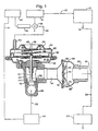
- FIG. 1 shows an engine equipped with an air injection system which is disclosed in US-A-5 203 872.
- the system generally indicated at 10 comprises an intake manifold 12, feeding an engine 14, which has an exhaust manifold and an exhaust pipe at 16.
- the pipe 16 feeds exhaust to an air injection joint 18.
- a run 20 of the exhaust pipe connects the joint 18 to a catalytic converter 22.
- the system for injecting secondary air at the joint 18 to supplement the exhaust stream comprises an air pump 24 having an outlet line 26 connected to the inlet port 28 of a supply valve 30.
- the valve 30 has an outlet port 32 connected to the inlet port 34 of a flap valve 36, which in turn has an outlet port 38 feeding the air injection joint 18 with air.
- the supply valve 30 and flap valve 36 are separate parts having independent housings in the prior art.
- the air pump 24 is turned on and off by the computer 40 via the signal line 41.
- the supply valve 30 is a conventional poppet valve having a disk 42 engaging a seat 44 and a stem 46 with an opposite or downstream end 48.
- the stem 46 is slidable along its axis to seat or unseat the disk 42 on the seat 44.
- the end 48 is positioned and moved by the diaphragm actuator 50 to open or close the valve 30.
- the diaphragm actuator 50 comprises an upper chamber 52 defined by the upper housing 54 and a lower chamber 56 defined by the lower housing 58.
- the upper and lower chambers 52 and 56 are separated by a diaphragm 60.
- the diaphragm 60 includes a rigid plate 62 which is fixed to the end 48.
- the spring 64 bears between and is located by the plate 62 and the upper housing 54.
- the lower chamber 56 is always vented to ambient air.
- the upper chamber 52 has a control port 65 receiving a vacuum line 66 which passes, via the solenoid valve 68, to the intake manifold 12 -- a conventional source of vacuum.
- the valve 68 is operated by the solenoid 70, which in turn is controlled by the computer 40.
- the flap valve 36 has an apertured web 72 defining a seat and an annular, flexible flap 74 attached at its center by the button 76 to the web 72.
- the flap 74 When the flap 74 is closed, as illustrated in Figure 1, it covers the apertures such as 78 of the seat 72.
- the flap 74 opens, responsive to a greater pressure in the inlet port 34 than in the outlet port 38, it deforms so its outer edge 80 moves axially away from the web 72, uncovering the apertures such as 78 and thus permitting flow.
- the flap 74 is protected against buffeting and excessive deformation by a flap retaining cone 82, also secured by the center button 76 to the web 72.
- the flap is lightly loaded by a spring 83 bearing between the cone 82 and the flap 74 to nominally close the flap 74 and control its deformation during opening.
- the valve opens or closes automatically, and permits air from the pump 24 to flow into the joint 18 while preventing reverse flow of the exhaust.
- the conventional air injection system of Figure 1 works as follows.
- the computer 40 starts the air pump 24 and signals the solenoid 70 to open the valve 68.
- the open valve 68 permits the intake manifold 12 to draw a partial vacuum in the upper chamber 52, raising the plate 62 of the diaphragm 60 against the bias of the spring 64, thus raising the stem 46 and disk 42 of the supply valve 30 away from the seat 44 and opening the valve 30.
- Air from the pump 24 thus traverses the supply valve 30, forces the flap 74 away from its seat 72, and passes via the apertures 78 into the outlet port 38 and into the air injection joint 18 where it mixes with the exhaust proceeding from the engine 14 via the exhaust pipe 16.
- the combined air and exhaust then proceed via the run 20 into and through the catalytic converter 22.
- the computer 40 signals the solenoid 70 to shift the valve 68 to isolate the intake manifold 12 from the line 66 and vent the line 66 to ambient pressure. This equalizes the pressure in the upper and lower chambers 52 and 56, allowing the spring 64 to force the plate 62, stem 46, and disk 42 toward the seat 44, thus closing the valve 30.
- the computer 40 also directs the air pump 24 to shut down at about the same time.
- the poppet valve 30 is oriented so it closes contrary to the direction of flow of the pump 24 in this embodiment so exhaust gas is doubly prevented from entering the line 26 by the valves 30 and 36.
- valves shown in FIGS. 2-6 have also been used in the prior art and are discussed below.
- a composite check valve comprising an electromagnetic solenoid having a portion being located in said flow passage, said solenoid having electrical winding defining a central magnetic flux axis and a plurality of magnetic segments, said magnetic segments including an armature and a pole piece adjacent said armature, said armature being physically translatable within a portion of said solenoid electrical winding along said flux axis relative to said pole piece; and energization of said electrical winding being effective to cause translation of said armature and said closure element.
- US-A-5203872 generally discloses composite check valve comprising: an inlet port; an outlet port a flow passage between said inlet port and said outlet port; a seat having an upstream side in fluid communication with said inlet port and a downstream side in fluid communication with said outlet port, said seat defining an aperture providing fluid communication between said upstream side and said downstream side; a first valve having a flap with obverse first and second sides, said flap being deformable between an open position for providing fluid communication between said inlet port and said outlet port, said first side of said flap being displaced from said seat in said open position, and a closed position for preventing such communication, said first side of said flap being substantially against said seat and substantially blocking flow through said aperture in said closed position; a translatable closure element attached to and movable with said armature, said closure element being positioned between said flap of said first valve and said outlet port, translation of said closure element being independent of said deformability of said flap of said first valve, said closure element being selectively engageable with said
- the aforesaid generally disclosed composite valve is characterised by an electromagnetic solenoid having a portion located in said flow passage, said solenoid having an electrical winding, a portion of which is encased in a bobbin, defining a central magnetic flux axis and a plurality of magnetic segments, said magnetic segments including an armature and a pole piece adjacent said armature, said armature being physically translatable within a portion of said solenoid electrical winding along said flux axis relative to said pole piece, said bobbin including a curvature extending across said central flux, the curvature and the armature forming a fluid chamber therebetween, and said armature including a slot forming a fluid passage connected to said fluid chamber.
- a composite valve in accordance with the present invention has the advantage that it reduces the number of parts required to regulate the introduction of secondary air into the exhaust stream. Another advantage is that the response time of the composite valve of the present invention is much faster than the response time of the prior art valves.
- the valve has a flap valve which is modified by a rigid, axially movable valve disk being superimposed over it.
- the rigid disk is connected to the solenoid armature and is moveable between an override position (closed) and a disengaged position (open) when the solenoid is energised. In its override position, the disk may engage the seat directly, urge the flap against its seat, or do both.
- the disk can be configured to physically protect the exposed surface of the disk while engaging it or the seat.
- the electromagnetic solenoid may be placed entirely within the flow passage.
- the solenoid armature is generally cylindrical and is located within the bobbin that encases the electrical winding.
- the closure member is attached to the stem that extends through the center of the pole piece and is attached to the center of the armature.
- the bobbin has a curved top to act as a fluid chamber. Additionally, the armature is slotted and there is a small hole in the closure member to prevent a vacuum from forming in the solenoid.
- the flap and seat function as a check valve permitting one-way flow of fluid when the override is disengaged. Engagement of the override prevents the flow of fluid in either direction past the flap. A portion of the flap captured between the disk and seat may act as a gasket to positively seal the valve in one embodiment.
- valves used in the prior art are shown in FIG. 1-6 and disclosed in U.S. Patent No. 5,203,872.
- the valve of FIG. 1 is described above.
- the composite valve 84 of Figure 2 directly replaces the supply valve 30, the flap valve 36, and the diaphragm actuator 50 shown in Figure 1.
- the system 10 is not changed materially by this substitution.
- the valve 84 has an inlet port 28 adapted to receive the effluent of a pump 24, an outlet port 38 adapted to deliver air to an air injection joint 18, and a control port 65 adapted to be connected to the vacuum line 66 of a system like that of Figure 1.
- the system description provided above will not be repeated here, and applies equally to the composite valve 84 shown in Figure 2.
- the valve generally indicated at 84 further comprises a seat 86 having an upstream side 88 in fluid communication with the inlet port 28 and a downstream side 90 in fluid communication with the outlet port 38.
- upstream and downstream are in reference to a fluid, such as secondary air, flowing in through the inlet port 28 and out through the outlet port 38.
- the seat 86 is defined by a web having apertures such as 92 providing fluid communication between the upstream side 88 and the downstream side 90 when the valve 84 is fully open.
- the seat 86 has a rigid lip 94 on its downstream side 90 encircling all the apertures 92.
- the downstream side 90 of the seat 86 could function without a well-defined lip 94.
- the web defining the seat 86 is inset in the body 96 and sealed by an annular gasket 98 having a downstream face 100 which overlaps the body 96 and the seat 86 and an upstream face 102 which is overlapped and captured by the flange 104 of the shell 106 defining the inlet port 28.
- This relationship of parts is maintained by rolling the outside portion of the flange 104 about the flange 108 of the body 96 to join them.
- the first valve element a flap 110
- the first valve element is annular, flexible, and has obverse first and second sides 112 and 114.
- the flap 110 is attached at its center by the button 116 to the seat 86, with the first side 112 of the flap 110 mounted adjacent to the downstream side 90 of the seat 86.
- the flap 110 is nominally deformable axially between a open position (in which it is deflected downstream, as shown in Figure 4) for allowing fluid flow through the seat 86 from the inlet port 28 to the outlet port 38 and an upstream or closed position, shown in Figures 2 and 3, in which the first side 112 is seated on the seat 86. When the flap 110 is closed, it covers the apertures such as 92 of the seat 86.
- the flap 110 When the flap 110 opens, responsive to a greater pressure in the inlet port 28 than in the outlet port 38, it uncovers the apertures such as 92 and thus permits a fluid to flow through the valve 84.
- the flap 110 is protected against buffeting and excessive deformation by a flap retaining cone 118, also secured by the center button 116 to the seat 86.
- the valve opens or closes automatically, and permits air from the pump 24 (as in Figure 1) to flow into the joint 18 ( Figure 1) while preventing reverse flow of the exhaust if the pressure difference between the inlet and outlet ports is reversed.
- valve element 110 and seat 86 of the illustrated embodiment form a flap valve
- other valve elements and corresponding seats are also contemplated.
- the flap 110 could be replaced by a hinged or captive plate, a captive ball, an iris diaphragm, a sluice or gate, a butterfly element, a piston slidable in a ported sleeve, a disk pivoted on the seat and having apertures which can be rotated into or out of registration with corresponding apertures in the seat, or other elements which move relative to a seat or analogous member to partially or fully open and close an aperture.
- valve disk 122 of Figures 2-4 and the valve disk 124 of Figure 5 are each embodiments of a second valve element or override means selectively operatively engageable with the seat and/or valve element for preventing flow through the apertures 92, notwithstanding any pressure difference experienced between the inlet port 28 and outlet port 38 in the environment in which the valve is designed to operate.
- the disk 122 functions by maintaining the element defined by the flap 110 in its closed position and preventing the element 110 from shifting normally, as illustrated in Figure 2.
- the disk 124 functions by bridging the element 110 entirely and directly seating against a concentric outer lip 126 of the seat 128.
- the disk 122 could also be modified by forming a depending flange about its periphery which covers the edge of the element 110, thus combining the functions of the disks 122 and 124.
- the valve disk 122 is a hat-shaped plate.
- the center or “crown" section 130 defines a recessed portion of the upstream face 132 of the valve disk 122 which faces the button 116 and the cone 118.
- the recess in the face 132 is provided so the disk 122 can bridge over the button 116 and cone 118 when the disk 122 is seated, as shown in Figure 2.
- the outside or “brim” section 134 of the disk 122 is substantially registered with the lip 94 and an annular portion of the flap 110.
- the brim section 134 includes a bearing surface which clamps the flap 110 against the lip 94 when the disk is engaged, as in Figure 2, and substantially clears the flap 110 when the disk is disengaged, as shown in Figures 3 and 4.
- the flap 110 acts as a seal between the brim 134 and the lip 94, while the relatively rigid disk 122 reinforces and protects the second side 114 of the flap 110 against a corrosive, hot, or otherwise adverse environment.
- the hat-shaped disk can be a cupped disk with no brim.
- the cone 118 and button 116 can be omitted and the disk 122 can be substantially flat on its lower or upstream side. This latter embodiment is particularly feasible if the flap 110 is replaced by a captive, rigid disk element.
- the disk 122 can be replaced by a rod or other shiftable member which is not substantially coextensive with the element 110 or the apertures 92, but is capable of holding the element 110 or a comparable valve element (preferably a rigid element) against its seat.
- the crown 30 can be skeletonized. However, this expedient is less preferred in the environment of engine exhaust because a skeletonized crown 30 would reduce the protection from exhaust gases afforded the flap 110 by the disk 122.
- valve disk 124 of this embodiment is also hat-shaped, and bridges the button 116 and cone 118, but also bridges the flap 110 to directly engage the concentric lip 126 of the seat 128.
- this construction may be advantageous because the disk 124 and outer lip 126 completely isolate the flap 110 from the outlet port 38 of the valve. In other cases, particularly if the outer lip 126 and the brim 136 of the disk 124 are each rigid and a tight seal between them is desired, the construction of Figure 5 may be less preferred.
- the axial proportions of the lip 126 and of the crown 138 of the disk 124 can be varied. If desired, the disk 124 can be flat and the lip 126 can extend higher than the cone 118 to provide a similar effect.
- the disk 122 has a brim section 134 that includes both a bearing surface which clamps the flap 110 against the lip 94 and a surface that is coextensive with the downstream side 90 of the seat 86 when the disk is engaged as in FIG. 6.
- the disks 122 and 124 each are attached to the upstream end of a stem 140.
- Each stem 140 has a downstream end which here is operated by essentially the same diaphragm actuator 50 employed to operate the supply valve 30 of Figure 1.
- the diaphragm actuator 50 of Figure 2 has the same construction, and the same reference characters, as the actuator of Figure 1.
- Alternate reciprocable actuators, such as a cam, a crank, or the like, are also contemplated herein.
- valve body 96, lower housing 58, and associated parts shown in Figure 1 are replaced by a one-piece molded and/or machined body 144 in Figure 2.
- the body 144 has an integral web 146 supporting a bronze stem bearing 148 and an annular elastomeric seal 150 to guide and seal the stem 140.
- FIG. 7 is directed to the present invention and shows a composite valve 84 where the secondary air control valve includes an electromagnetic solenoid valve apparatus 200.
- the composite valve of FIG. 7 combines in an integral structure the component parts of the supply valve 30, the flap valve 36, the diaphragm actuator 50, the solenoid 70, the valve 68, control port 65 and vacuum line 66 shown in FIGS. 1 and 2.
- the valve 84 in FIG. 7 has an inlet port 28 adapted to receive the effluent of a pump 24, an outlet port 38 adapted to deliver air to an air injection joint 18, and an electrical connector 202 adapted to be connected to a computer 40.
- the electromagnetic solenoid 200 further comprises an iron outer member or a can 204, a hollow cylindrical magnetic core pole piece or center member 206 having a center passage 214, a hollow cylindrical magnetic armature 208 having a center opening 216, an electrical winding 210 mounted about center member 206 and armature 208, and a coil spring 220.
- Spring 220 exerts a biasing force that separates pole piece 206 and armature 208 when electrical winding 210 is not energized.
- the separation between pole piece 206 and armature 208 defines an air gap 226.
- the electrical winding 210 is encased on its upper, lower and inner diameter surfaces in a bobbin 212 generally of plastic material, which bobbin 212 surrounds and engages the pole piece 206 and the armature 208 along most of their axial dimensions.
- Wire 236 maintains electrical contact between electrical winding 210 and electrical connector 202.
- the electrical connector is connected to a suitable source of power, which can include direct current, alternating current, a pulse width modulated (PWM) circuit, an automobile on-board computer functioning as a signal source or the like.
- PWM pulse width modulated
- Armature 208 is connected to valve disk or closure element 122 by stem 140.
- the upstream end 218 of stem 140 may pass through center passage 214 of the pole piece 206, and be attached to armature 208.
- the upstream end 218 of stem 140 is press fit into the center opening 216 of armature 208
- the downstream end 222 of the stem 140 is connected to disk 122.
- the retaining cone 118 is attached to pole piece 206. This relationship holds the valve element 110, conical spring 120, and seat 86 in place. In the preferred embodiment, retaining cone 118 is riveted to pole piece 206.
- the web defining the seat 86 is inset in the body 96 and sealed by annular gasket 98 having a downstream face 100 which overlaps the body 96 and an upstream face 102 which is overlapped by the downstream side 90 of the seat 86.
- the upstream side 88 of the seat 86 is overlapped and captured by the flange 104 of the shell 106 defining the inlet port 28. This relationship of parts is maintained by clasp 224.
- the joinder of the body 96 and the shell 106 define a flow passage 300 between the inlet port 28 and the outlet port 38 of the composite valve 84.
- the electromagnetic solenoid 200 is contained entirely within the flow passage 300 of the composite valve 84.
- the positioning of the electromagnetic solenoid 200 inside the flow passage 300 is maintained by guides 238 of the shell 106. Placing the electromagnetic solenoid 200 inside flow passage 300 is advantageous because the air flow through flow passage 300 helps to cool electromagnetic solenoid 200. Moreover, placing the electromagnetic solenoid inside the valve provides a unitary valve and electromagnetic actuator, which reduces the size and number of components.
- the computer 40 starts the air pump 24 and signals the electrical connector 202 to energize the electrical winding 204.
- the electrical connecter 202 may supply either constant DC voltage or Pulse Width Modulated (PWM) voltage, hence making the electromagnetic solenoid 200 have variable position proportional to the signal duty cycle.
- PWM Pulse Width Modulated
- An electromagnetic flux is induced when the current is supplied from the electrical connector 202 to the electrical winding 204.
- the armature 208 is responsive to the electromagnetic flux.
- energization of electrical winding 204 causes the movement of the closure element 122 to allow fluid flow.
- the armature 208 is attracted toward pole piece 206.
- the armature 208 When totally energized, or 100% duty cycle, the armature 208 will be at the minimum distance from the pole piece 206, and the disk or closure element 122 will be at its maximum distance from the seat 86.
- the force (magnetic flux) required to move armature 208 is dependent on the bias of spring 220.
- the bias of spring 220 will cause the armature 208 to be the maximum distance from pole piece 206. That distance defines the maximum air gap 226 between pole piece 206 and armature 208.
- the disk 122 will rigidly close and seal flap 110. In that situation, the disk 122 acts as a sealing gasket, allowing no flow through the flap 110 in either direction.
- bobbin 212 has curvature 230 creating chamber 232. Chamber 232 acts as a reservoir in case any backflow should occur.
- armature 208 is fluted and defines slot 228. Slot 228 prevents a vacuum from forming in air gap 226 in case some backflow should occur.
- disk 122 has a hole 234 which also helps to prevent a vacuum from forming in the case that backflow should occur.
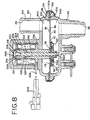
- FIG. 8 illustrates an alternate embodiment of the composite valve 84 with an electromagnetic solenoid 200.
- the electromagnetic solenoid 200 is not contained entirely inside the composite valve 84. Referring to FIG. 8, placing the electromagnetic solenoid 200 outside the composite valve 84 creates an offset flow passage 300, but still allows the integral valve and solenoid assembly.
- the web defining the seat 86 is inset in the body 96 and sealed by annular gasket 98 having a downstream face 100 which overlaps the body 96 and the upstream side 88 of the seat 86, and an upstream face 102 which is overlapped by the flange 104 of shell 106 defining the inlet port 28.
- the downstream side 90 of the seat 86 is overlapped and captured by the flange 108 of the body 96 defining the outlet port 28. This relationship of parts is maintained by clasp 224.
- the present invention can also be used to more finely regulate the flow from the inlet port 28 to the outlet port 38 by allowing restricted opening of the flap 110.
- PWM voltage is supplied to electrical winding 210 allowing the disk 122 to vary its position between being fully seated (as in Figures 7 and 8) and fully disengaged (as in Figures 3 and 4).
- the disk 122 thus can be moved to any point between its positions in Figures 7 and 3.
- the disk 122 can allow the flap 110 to open partially, thus reducing the amount of air flowing through the seat 86.
- This expedient can be used to gradually reduce the amount of air introduced into the exhaust of the engine 14, instead of abruptly cutting off the air flow.
- valve can be inexpensive, durable, and reliable.
- a flexible flap and a rigid valve disk cooperate to provide a composite valve function.
- the flap valve can be overridden and at the same time protected against damage from the fluid contacting it.
- the illustrated valve can alternately function as a check valve and as a positively closing valve. It can include a flap as a first valve element which also serves as a gasket for a superimposed poppet element.
Landscapes
- Engineering & Computer Science (AREA)
- Chemical & Material Sciences (AREA)
- Chemical Kinetics & Catalysis (AREA)
- Health & Medical Sciences (AREA)
- Toxicology (AREA)
- Combustion & Propulsion (AREA)
- Mechanical Engineering (AREA)
- General Engineering & Computer Science (AREA)
- Exhaust Gas After Treatment (AREA)
Claims (8)
- Verbundrückschlagventil (84) mit:einem Einlaß (28),einem Auslaß (38),einem Strömungskanal (300) zwischen Einlaß (28) und Auslaß (38),einem Sitz (86), dessen stromauf gelegene Seite (88) in Strömungsverbindung mit dem Einlaß (28) und dessen stromab gelegene Seite (90) in Strömungsverbindung mit dem Auslaß (38) steht und der eine Öffnung (92) zur Strömungsverbindung zwischen stromauf gelegener Seite (88) und stromab gelegener Seite (90) hat,einem ersten Ventil mit einer Klappe (110), die eine erste und eine zweite gegenüberliegende Seite (112, 114) hat und verformbar ist, zwischen einer offenen Stellung zur Strömungsverbindung zwischen Einlaß (28) und Auslaß (38), in der die erste Seite (112) vom Sitz (86) abgehoben ist, und einer geschlossenen Stellung zum Verhindern der Strömungsverbindung, in der die erste Seite (112) im wesentlichen am Sitz (86) anliegt und Strömung durch die Öffnung (92) verhindert,einem verschieblichen Verschlußglied (122), das an einem Anker (208) angebracht und mit diesem beweglich ist und zwischen der Klappe (110) des ersten Ventils und dem Auslaß (38) angeordnet ist, wobei eine Verschiebung des Verschlußgliedes (122) unabhängig von der Verformbarkeit der Klappe (110) des ersten Ventils ist und das Verschlußglied (122) wahlweise an der Klappe (110) des ersten Ventils anliegen kann, um die Klappe (110) in der geschlossenen Stellung zu halten und die Verformung der Klappe (110) zu verhindern, wobeieine Bestromung einer Spule (210) eine Verschiebung des Ankers (208) und des Verschlußgliedes (122) bewirkt, dadurch gekennzeichnet, daßein Elektromagnet (200) einen im Strömungskanal (300) angeordneten Abschnitt hat und die Spule (210) aufweist, die teilweise von einem Spulengehäuse (212) umgeben ist, das eine zentrale magnetische Flußachse und mehrere magnetische Abschnitte bildet, welche einen Anker (208) und diesem benachbart ein Polstück (206) umfassen, wobei der Anker (208) physikalisch in einem Teil der Spule (206) des Elektromagneten entlang der Flußachse gegenüber dem Polstück (206) verschieblich ist, das Spulengehäuse (206) einen Deckel (230) über der zentralen magnetischen Flußachse aufweist, der Deckel (230) mit dem Anker (208) eine Fluidkammer (232) bildet und der Anker (208) einen Schlitz (228) aufweist, der einen mit der Fluidkammer (223) verbundenen Strömungskanal bildet.
- Verbundventil (84) nach Anspruch 1, bei dem das Verschlußglied (122) an der zweiten Seite (114) der Klappe (110) anliegt, um die Klappe (110) wahlweise in der geschlossenen Stellung halten zu können.
- Verbundventil (84) nach Anspruch 1 oder 2, bei dem das Verschlußglied (122) eine erste und eine zweite Seite hat, wobei die erste Seite gegenüber der zweiten Seite (114) der Klappe (110) liegt und einen Abschnitt hat, der dem Sitz (86) gegenüberliegt und im wesentlichen gleiche Ausdehnung wie dieser hat.
- Verbundventil (84) nach einem der vorhergehenden Ansprüche, bei dem der Elektromagnet (200) vollständig im Strömungskanal (300) angeordnet ist.
- Verbundventil (84) nach einem der vorhergehenden Ansprüche, bei dem der Anker (208) im Spulengehäuse (212) angeordnet ist, im wesentlichen zylindrisch ist und axial entlang eines zylindrischen Kanals (216) in der Mitte der Spule (210) verschieblich ist, und das Polstück (206) einen zylindrischen Abschnitt in der Spule (210) aufweist.
- Verbundventil (84) nach einem der vorhergehenden Ansprüche, bei dem das Verschlußglied (122) mit dem Anker (208) über einen zylindrischen Schaft (140) verbunden ist, der sich vom Verschlußglied (122) durch das Polstück (206) erstreckt und axial entlang der zentralen magnetischen Flußachse verschieblich ist.
- Verbundventil (84) nach Anspruch 6, bei dem der zylindrische Schaft (140) durch die Mitte des Polstückes (206) und die Mitte des Ankers (208) verläuft.
- Verbundventil (84) nach einem der vorhergehenden Ansprüche, bei dem das Verschlußglied (122) eine erste und eine zweite Seite aufweist und eine Öffnung (234) eine Verbindung zwischen der ersten und der zweiten Seite des Verschlußgliedes (122) schafft.
Applications Claiming Priority (2)
| Application Number | Priority Date | Filing Date | Title |
|---|---|---|---|
| US254165 | 1994-06-06 | ||
| US08/254,165 US5421366A (en) | 1994-06-06 | 1994-06-06 | Solenoid operated air control and check valve |
Publications (2)
| Publication Number | Publication Date |
|---|---|
| EP0686757A1 EP0686757A1 (de) | 1995-12-13 |
| EP0686757B1 true EP0686757B1 (de) | 1998-08-26 |
Family
ID=22963184
Family Applications (1)
| Application Number | Title | Priority Date | Filing Date |
|---|---|---|---|
| EP95302249A Expired - Lifetime EP0686757B1 (de) | 1994-06-06 | 1995-04-04 | Elektromagnetisches Luftregelventil und Rückschlagventil |
Country Status (4)
| Country | Link |
|---|---|
| US (1) | US5421366A (de) |
| EP (1) | EP0686757B1 (de) |
| CA (1) | CA2146289A1 (de) |
| DE (1) | DE69504245T2 (de) |
Families Citing this family (19)
| Publication number | Priority date | Publication date | Assignee | Title |
|---|---|---|---|---|
| GB2308989B (en) * | 1996-01-12 | 1997-11-19 | Steven Valisko | Exhaust manifold device |
| US7013916B1 (en) | 1997-11-14 | 2006-03-21 | Air Products And Chemicals, Inc. | Sub-atmospheric gas delivery method and apparatus |
| GB2344614B (en) * | 1998-12-11 | 2000-11-08 | Steven Valisko | Exhaust manifold device |
| US6209563B1 (en) | 2000-01-07 | 2001-04-03 | Saturn Electronics & Engineering, Inc. | Solenoid control valve |
| US6321767B1 (en) | 2000-01-10 | 2001-11-27 | Saturn Electronics & Engineering, Inc. | High flow solenoid control valve |
| US6581634B2 (en) | 2000-01-10 | 2003-06-24 | Saturn Electronics & Engineering, Inc. | Solenoid control valve with particle gettering magnet |
| US6453667B1 (en) | 2000-09-01 | 2002-09-24 | Siemens Automotive Inc. | Air control valve and method for engine exhaust gas treatment |
| US6648012B2 (en) | 2001-06-13 | 2003-11-18 | Applied Materials, Inc. | Non-return valve override device |
| DE10240265B4 (de) * | 2002-08-31 | 2005-09-01 | Daimlerchrysler Ag | Kombiventil |
| US7150299B2 (en) | 2003-09-12 | 2006-12-19 | Air Products And Chemicals, Inc. | Assembly and method for containing, receiving and storing fluids and for dispensing gas from a fluid control and gas delivery assembly having an integrated fluid flow restrictor |
| US20090166274A1 (en) * | 2007-05-24 | 2009-07-02 | Eaton Corporation | Engine valve with a combined engine oil filter and valve actuator solenoid |
| US8281810B2 (en) * | 2008-04-30 | 2012-10-09 | The Viking Corporation | Dry valve for sprinkler system |
| CN102782282B (zh) * | 2010-03-18 | 2016-01-27 | 三菱电机株式会社 | 空气旁通阀装置 |
| DE102015219207B3 (de) * | 2015-10-05 | 2017-02-09 | Conti Temic Microelectronic Gmbh | Druckverteiler für ein Kraftfahrzeug |
| GB201611246D0 (en) * | 2016-06-29 | 2016-08-10 | Ge Oil & Gas Uk Ltd | Gas venting |
| AT16539U1 (de) * | 2018-09-10 | 2019-12-15 | Msg Mechatronic Systems Gmbh | Ventilvorrichtung |
| DE102020106212A1 (de) * | 2020-03-06 | 2021-09-09 | Wabco Europe Bvba | Fluidventil, Ventilanordnung und Bremsanlage |
| DE102020118063A1 (de) * | 2020-07-08 | 2022-01-13 | Pierburg Gmbh | Ventilvorrichtung für eine Verbrennungskraftmaschine |
| US11965609B2 (en) * | 2021-07-08 | 2024-04-23 | Kamtec Inc. | Valve for preventing backflow and valve module |
Family Cites Families (33)
| Publication number | Priority date | Publication date | Assignee | Title |
|---|---|---|---|---|
| CA883937A (en) * | 1971-10-19 | Westfalia Dinnendahl Groppel | Apparatus for drying and pre-heating of pulverulent material, particularly raw cement material | |
| US1385058A (en) * | 1920-05-29 | 1921-07-19 | Frank A Warter | Valve |
| CH430357A (de) * | 1963-07-08 | 1967-02-15 | S Gravenhage Gemeente | Plattenventil |
| US3897042A (en) * | 1971-12-20 | 1975-07-29 | Henry J Kachergis | Ball cock valve |
| US3785152A (en) * | 1972-11-13 | 1974-01-15 | Gen Motors Corp | Inlet throttled air pump for exhaust emission control |
| US3964259A (en) * | 1973-08-06 | 1976-06-22 | Acf Industries, Incorporated | Multi condition relief valve |
| IT1024357B (it) * | 1974-01-23 | 1978-06-20 | Deutsche Vergaser Gmbh Co Kg | Regolatore per dosare una tita ausiliaria di aria al lo scopondi migliorare la combustione in motori a combustioni interna o per meglio bruciare i gas di scarico di tali motori |
| US3940928A (en) * | 1974-02-11 | 1976-03-02 | General Motors Corporation | Air diverter valve |
| JPS50144814A (de) * | 1974-05-11 | 1975-11-20 | ||
| US3950943A (en) * | 1974-05-20 | 1976-04-20 | General Motors Corporation | Air diverter valve |
| JPS531416B2 (de) * | 1974-09-09 | 1978-01-19 | ||
| US3964510A (en) * | 1974-11-25 | 1976-06-22 | G & R Industries, Inc. | Live well valve |
| US3964515A (en) * | 1974-12-23 | 1976-06-22 | Acf Industries, Incorporated | By-pass valve with pressure relief feature |
| US3942321A (en) * | 1975-02-11 | 1976-03-09 | General Motors Corporation | Engine secondary air control valve |
| US3948045A (en) * | 1975-04-21 | 1976-04-06 | General Motors Corporation | Air control valve |
| US3992878A (en) * | 1975-10-03 | 1976-11-23 | Ford Motor Company | Engine secondary air flow control system |
| JPS5273231A (en) * | 1975-12-17 | 1977-06-18 | Toyota Motor Corp | Internal combustion engines for vehicles |
| JPS52127511A (en) * | 1976-04-19 | 1977-10-26 | Nippon Soken Inc | Exhaust gas purifying system in internal combustion engine |
| JPS52142127A (en) * | 1976-05-24 | 1977-11-26 | Nissan Motor Co Ltd | Exhaust purifier in the internal combustion engine |
| JPS52153021A (en) * | 1976-06-15 | 1977-12-19 | Nissan Motor Co Ltd | Secondary air supply regulating system |
| JPS54121323A (en) * | 1978-03-13 | 1979-09-20 | Toyota Motor Corp | Exhaust gas control actuator |
| US4193212A (en) | 1978-05-17 | 1980-03-18 | Al Kufaishi Hassan A | Unified English pronouncing alphabet |
| DE3032403A1 (de) * | 1980-08-28 | 1982-04-01 | Wabco Fahrzeugbremsen Gmbh, 3000 Hannover | Halbautomatische getriebesteuerung |
| US4425620A (en) * | 1981-01-28 | 1984-01-10 | Steiger Tractor, Inc. | Electrical control for power shift transmission |
| US4875499A (en) * | 1981-10-16 | 1989-10-24 | Borg-Warner Corporation | Proportional solenoid valve |
| US4507736A (en) * | 1982-02-11 | 1985-03-26 | Wabco Fahrzeugbremsen Gmbh | Transmission gear shift control system |
| US4477051A (en) * | 1982-05-18 | 1984-10-16 | Ben Yehuda Avram | Flow control valve |
| US4550749A (en) * | 1984-03-12 | 1985-11-05 | C. R. Bard, Inc. | Adjustable check valve |
| JPH0249434B2 (ja) * | 1984-06-05 | 1990-10-30 | Matsushita Electric Ind Co Ltd | Heishikinotsukiatsuryokuseigyoben |
| US4634093A (en) * | 1985-10-07 | 1987-01-06 | Vilter Manufacturing Corporation | Mounting means for valve disc |
| US4887792A (en) * | 1988-10-06 | 1989-12-19 | Kuo Ping Song | Stop-check valve |
| DE4025267C2 (de) * | 1990-08-09 | 2000-06-08 | Pierburg Ag | Rückschlagventil für eine Gasleitung |
| US5203872A (en) * | 1991-03-21 | 1993-04-20 | Borg-Warner Automotive Electronic & Mechanical Systems Corporation | Secondary air control and check valves |
-
1994
- 1994-06-06 US US08/254,165 patent/US5421366A/en not_active Expired - Lifetime
-
1995
- 1995-04-04 EP EP95302249A patent/EP0686757B1/de not_active Expired - Lifetime
- 1995-04-04 CA CA002146289A patent/CA2146289A1/en not_active Abandoned
- 1995-04-04 DE DE69504245T patent/DE69504245T2/de not_active Expired - Lifetime
Also Published As
| Publication number | Publication date |
|---|---|
| US5421366A (en) | 1995-06-06 |
| DE69504245T2 (de) | 1999-01-07 |
| CA2146289A1 (en) | 1995-12-07 |
| EP0686757A1 (de) | 1995-12-13 |
| DE69504245D1 (de) | 1998-10-01 |
Similar Documents
| Publication | Publication Date | Title |
|---|---|---|
| US5421366A (en) | Solenoid operated air control and check valve | |
| US5345967A (en) | Secondary air control and check valves | |
| EP1869308B1 (de) | Abgasrückführventil mit Ruhelage | |
| US4662604A (en) | Force balanced EGR valve with position feedback | |
| US5435519A (en) | EGR system having fast-acting EGR valve | |
| US5326070A (en) | Solenoid valve | |
| US5511531A (en) | EGR valve with force balanced pintle | |
| US4310142A (en) | Fuel pressure regulator assembly | |
| JPH10231755A (ja) | 液化燃料用燃料インジェクタ | |
| US4151819A (en) | Exhaust gas pressure responsive valve assembly | |
| US4165611A (en) | Secondary air feeding device for an internal combustion engine | |
| EP1235016B1 (de) | Gassteuerventil | |
| US6109302A (en) | Three-way gas management valve | |
| US4070830A (en) | Integral air switching diverter valve | |
| US4601277A (en) | System for combined EGR and idle speed control | |
| EP0496487B1 (de) | Emissionssteuerungssystem | |
| US4342194A (en) | Electric air control switching valve | |
| US4331113A (en) | Device for selective combustion in a multi-cylinder engine | |
| CA1069398A (en) | Air switching diverter valve | |
| US4174610A (en) | Power cruise diverter valve | |
| JPH0374690A (ja) | 電磁式調節部材 | |
| US4480661A (en) | Air flow control valve means | |
| US4510904A (en) | Vacuum operated idle speed control device | |
| CA1303587C (en) | Vacuum regulator valve unit | |
| US4505237A (en) | Vacuum control device |
Legal Events
| Date | Code | Title | Description |
|---|---|---|---|
| PUAI | Public reference made under article 153(3) epc to a published international application that has entered the european phase |
Free format text: ORIGINAL CODE: 0009012 |
|
| AK | Designated contracting states |
Kind code of ref document: A1 Designated state(s): DE FR GB |
|
| 17P | Request for examination filed |
Effective date: 19960219 |
|
| 17Q | First examination report despatched |
Effective date: 19970516 |
|
| GRAG | Despatch of communication of intention to grant |
Free format text: ORIGINAL CODE: EPIDOS AGRA |
|
| GRAG | Despatch of communication of intention to grant |
Free format text: ORIGINAL CODE: EPIDOS AGRA |
|
| GRAH | Despatch of communication of intention to grant a patent |
Free format text: ORIGINAL CODE: EPIDOS IGRA |
|
| GRAH | Despatch of communication of intention to grant a patent |
Free format text: ORIGINAL CODE: EPIDOS IGRA |
|
| GRAA | (expected) grant |
Free format text: ORIGINAL CODE: 0009210 |
|
| AK | Designated contracting states |
Kind code of ref document: B1 Designated state(s): DE FR GB |
|
| REF | Corresponds to: |
Ref document number: 69504245 Country of ref document: DE Date of ref document: 19981001 |
|
| ET | Fr: translation filed | ||
| PLBI | Opposition filed |
Free format text: ORIGINAL CODE: 0009260 |
|
| PLBF | Reply of patent proprietor to notice(s) of opposition |
Free format text: ORIGINAL CODE: EPIDOS OBSO |
|
| 26 | Opposition filed |
Opponent name: PIERBURG AG Effective date: 19990512 |
|
| PLBF | Reply of patent proprietor to notice(s) of opposition |
Free format text: ORIGINAL CODE: EPIDOS OBSO |
|
| PLBF | Reply of patent proprietor to notice(s) of opposition |
Free format text: ORIGINAL CODE: EPIDOS OBSO |
|
| PGFP | Annual fee paid to national office [announced via postgrant information from national office to epo] |
Ref country code: GB Payment date: 20000317 Year of fee payment: 6 |
|
| PLBO | Opposition rejected |
Free format text: ORIGINAL CODE: EPIDOS REJO |
|
| PGFP | Annual fee paid to national office [announced via postgrant information from national office to epo] |
Ref country code: FR Payment date: 20000405 Year of fee payment: 6 |
|
| PLBN | Opposition rejected |
Free format text: ORIGINAL CODE: 0009273 |
|
| STAA | Information on the status of an ep patent application or granted ep patent |
Free format text: STATUS: OPPOSITION REJECTED |
|
| 27O | Opposition rejected |
Effective date: 20000417 |
|
| PG25 | Lapsed in a contracting state [announced via postgrant information from national office to epo] |
Ref country code: GB Free format text: LAPSE BECAUSE OF NON-PAYMENT OF DUE FEES Effective date: 20010404 |
|
| PG25 | Lapsed in a contracting state [announced via postgrant information from national office to epo] |
Ref country code: FR Free format text: THE PATENT HAS BEEN ANNULLED BY A DECISION OF A NATIONAL AUTHORITY Effective date: 20010430 |
|
| GBPC | Gb: european patent ceased through non-payment of renewal fee |
Effective date: 20010404 |
|
| REG | Reference to a national code |
Ref country code: FR Ref legal event code: ST |
|
| REG | Reference to a national code |
Ref country code: FR Ref legal event code: GC |
|
| PGFP | Annual fee paid to national office [announced via postgrant information from national office to epo] |
Ref country code: DE Payment date: 20140430 Year of fee payment: 20 |
|
| REG | Reference to a national code |
Ref country code: DE Ref legal event code: R071 Ref document number: 69504245 Country of ref document: DE |
|
| REG | Reference to a national code |
Ref country code: DE Ref legal event code: R071 Ref document number: 69504245 Country of ref document: DE |