EP0686754B1 - Steuervorrichtung mit einziger Welle, insbesondere für Brennkraftmaschinen - Google Patents
Steuervorrichtung mit einziger Welle, insbesondere für Brennkraftmaschinen Download PDFInfo
- Publication number
- EP0686754B1 EP0686754B1 EP95201083A EP95201083A EP0686754B1 EP 0686754 B1 EP0686754 B1 EP 0686754B1 EP 95201083 A EP95201083 A EP 95201083A EP 95201083 A EP95201083 A EP 95201083A EP 0686754 B1 EP0686754 B1 EP 0686754B1
- Authority
- EP
- European Patent Office
- Prior art keywords
- variator
- camshaft
- cams
- sleeves
- shafts
- Prior art date
- Legal status (The legal status is an assumption and is not a legal conclusion. Google has not performed a legal analysis and makes no representation as to the accuracy of the status listed.)
- Expired - Lifetime
Links
- 238000002485 combustion reaction Methods 0.000 title claims 2
- 239000003921 oil Substances 0.000 description 5
- 239000010687 lubricating oil Substances 0.000 description 2
- 230000005540 biological transmission Effects 0.000 description 1
- 230000008878 coupling Effects 0.000 description 1
- 238000010168 coupling process Methods 0.000 description 1
- 238000005859 coupling reaction Methods 0.000 description 1
- 230000001105 regulatory effect Effects 0.000 description 1
Images

Classifications
-
- F—MECHANICAL ENGINEERING; LIGHTING; HEATING; WEAPONS; BLASTING
- F01—MACHINES OR ENGINES IN GENERAL; ENGINE PLANTS IN GENERAL; STEAM ENGINES
- F01L—CYCLICALLY OPERATING VALVES FOR MACHINES OR ENGINES
- F01L1/00—Valve-gear or valve arrangements, e.g. lift-valve gear
- F01L1/34—Valve-gear or valve arrangements, e.g. lift-valve gear characterised by the provision of means for changing the timing of the valves without changing the duration of opening and without affecting the magnitude of the valve lift
- F01L1/344—Valve-gear or valve arrangements, e.g. lift-valve gear characterised by the provision of means for changing the timing of the valves without changing the duration of opening and without affecting the magnitude of the valve lift changing the angular relationship between crankshaft and camshaft, e.g. using helicoidal gear
- F01L1/34403—Valve-gear or valve arrangements, e.g. lift-valve gear characterised by the provision of means for changing the timing of the valves without changing the duration of opening and without affecting the magnitude of the valve lift changing the angular relationship between crankshaft and camshaft, e.g. using helicoidal gear using helically teethed sleeve or gear moving axially between crankshaft and camshaft
- F01L1/34406—Valve-gear or valve arrangements, e.g. lift-valve gear characterised by the provision of means for changing the timing of the valves without changing the duration of opening and without affecting the magnitude of the valve lift changing the angular relationship between crankshaft and camshaft, e.g. using helicoidal gear using helically teethed sleeve or gear moving axially between crankshaft and camshaft the helically teethed sleeve being located in the camshaft driving pulley
Definitions
- a single-shaft timing system suitable for permitting the phase variation indicated above is described, for example, in EP-A-0 397 540.
- EP-A-0 582 846 and EP-A-0 254 058 are also prior art to the present invention.
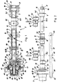
- the camshaft 2 comprises two tubular half-shafts 6, 7 joined together by a central sleeve 8 and carrying first and second end sleeves 9, 10, respectively, at their axially opposite ends.
- the two half-shafts 6, 7 are fitted with interference in the respective sleeves 8, 9 and 10 so that, once assembled, the camshaft 2 has a unitary character.
Landscapes
- Engineering & Computer Science (AREA)
- Mechanical Engineering (AREA)
- General Engineering & Computer Science (AREA)
- Valve-Gear Or Valve Arrangements (AREA)
- Valve Device For Special Equipments (AREA)
Claims (13)
- Steuerzeitvorrichtung vom sogenannten "Einwellen"-Typ für insbesondere Verbrennungsmotoren, mit einer Nockenwelle (2) mit wenigstens ersten und zweiten Sätzen an Nocken (4a-d; 5a-d), einem Phasenvariator (3) mit einer Antriebswelle (51), die sich in der Nockenwelle (2) koaxial erstreckt und damit zur Veränderung des Phasenwinkels zwischen den Nockensätzen (4a-d; 5a-d) in Wirkverbindung steht, wobei die Nockenwelle einstückig ist und die Nocken daran axial fixiert sind und die Nocken des zweiten Satzes (5 a-d) sowie des ersten Satzes (4 a-d) zur Drehung mit der Nockenwelle (2) und mit der Antriebswelle (51) festgelegt sind, wobei der Phasonvariator (3) erste und zweite Variatorelemente (40, 51) besitzt, die als eine Folge einer aktiven Betätigung des Variators relativ zueinander drehbar sind und die Variatorelemente zur Drehung mit der Nockenwelle (2) und mit der Antriebswelle (51) festgelegt sind zur Herbeiführung einer Phasonveränderung zwischen den Nocken der Sätze (4 a-d; 5 a-d) in Folge einer aktiven Betätigung des Variators (3), dadurch gekennzeichnet, daß die Nockenwelle (2) wenigstens zwei Halbwellen (6, 7) aufweist, die über eine mittige Büchse (8) miteinander verbunden sind.
- Vorrichtung nach Anspruch 1, wobei die ersten und zweiten Variatorelemente ein Gehäuse (40) des Variators beziehungsweise dgr Betätigungswelle (51) sind und die Nockenwelle (2) zur Drehung mit dem Gehäuse (40) festgelegt ist.
- Vorrichtung nach Anspruch 1 oder Anspruch 2, wobei die mittige Büchse (8) einen Teil der Nocken trägt.
- Vorrichtung nach Anspruch 2 oder Anspruch 3, wobei die Halbwellen (6, 7) in der mittigen Büchse (8) mit Überlagerung eingepaßt sind.
- Vorrichtung nach einem oder mehreran der vorstehenden Ansprüche, wobei die Halbwellen (6, 7) ihrerseits mit jeweiligen Endbüchsen (9, 10) verbunden sind und die Büchsen zusammen alle Nocken (5 a-d) des zweiten Satzes tragen.
- Vorrichtung nach Anspruch 5, wobei eine der Endbüchsen eine Einrichtung (22) zur Befestigung des Gehäuses (40) des Variators (3) aufweist.
- Vorrichtung nach einem oder mehreren der vorstehenden Ansprüche, wobei die Nocken (4 a-d) des ersten Satzes an Büchsen (30, 31) ausgebildet sind, die an den Halbwellen (6, 7) drehbar angeordnet sind.
- Vorrichtung nach Anspruch 7, wobei die drehbaren Büchsen (30, 31) an Stellen zwischen der mittigen Büchse (8) und den Endbüchsen (9,10) angeordnet sind.
- Vorrichtung nach Anspruch 7 oder Anspruch 8, wobei die drehbaren Büchsen (30,31) an den Halbwellen (6, 7) durch die Endbüchsen (9, 10) und die mittige Büchse (8) axial festgelegt sind.
- Vorrichtung nach einem oder mehreron der Ansprüche 7 bis 9, wobei die drehbaren Büchsen (30, 31) mit der Antriebswelle (51) des Variators mittels Stiften (36, 37) verbunden sind, die in die drehbaren Büchsen und in die Antriebswelle getrieben sind und sich durch schlitzähnliche Öffnungen (36a, 36b) in den entsprechenden Halbwellen (6, 7) hindurch erstrecken.
- Vorrichtung nach einem oder mehreren der vorstehenden Ansprüche, bei dem die Winkelstellung des Gehäuses (40) des Variators (3) relativ zu der Nockenwelle einstelbar ist.
- Vorrichtung nach Anspruch 11, wobei das Gehäuse einen Flansch zur Befestigung an der Nockenwelle trägt und der Flansch schlitzähnliche Öffnungen (44) besitzt.
- Vorrichtung nach einem oder mehreren der vorstehenden Ansprüche, wobei ein Verzahnungsabschnitt (50) an einem axialen Ende der Antriebswelle (51) des Variators (3) vorgesehen ist und sich ein Kolben (48) des Variators (3) daran in einem verschieblichen Eingriff befindet.
Applications Claiming Priority (2)
| Application Number | Priority Date | Filing Date | Title |
|---|---|---|---|
| IT1994PD000087A IT1268966B1 (it) | 1994-05-12 | 1994-05-12 | Sistema di distribuzione monoalbero, in particolare per motori acombustione interna. |
| ITPD940087 | 1994-05-12 |
Publications (3)
| Publication Number | Publication Date |
|---|---|
| EP0686754A2 EP0686754A2 (de) | 1995-12-13 |
| EP0686754A3 EP0686754A3 (de) | 1996-04-10 |
| EP0686754B1 true EP0686754B1 (de) | 1999-10-27 |
Family
ID=11390679
Family Applications (1)
| Application Number | Title | Priority Date | Filing Date |
|---|---|---|---|
| EP95201083A Expired - Lifetime EP0686754B1 (de) | 1994-05-12 | 1995-04-27 | Steuervorrichtung mit einziger Welle, insbesondere für Brennkraftmaschinen |
Country Status (3)
| Country | Link |
|---|---|
| EP (1) | EP0686754B1 (de) |
| DE (1) | DE69512962T2 (de) |
| IT (1) | IT1268966B1 (de) |
Cited By (2)
| Publication number | Priority date | Publication date | Assignee | Title |
|---|---|---|---|---|
| EP2527607A2 (de) | 2011-05-27 | 2012-11-28 | Schwäbische Hüttenwerke Automotive GmbH | Vorrichtung zur Verstellung der relativen Drehwinkelposition geschachtelter Nockenwellen |
| DE10346448B4 (de) | 2003-10-07 | 2017-03-30 | Daimler Ag | Nockenwellenversteller für eine Brennkraftmaschine |
Families Citing this family (5)
| Publication number | Priority date | Publication date | Assignee | Title |
|---|---|---|---|---|
| DE102005040934A1 (de) | 2005-02-03 | 2006-08-17 | Mahle International Gmbh | Verstellbare Nockenwelle, insbesondere für Verbrennungsmotoren von Kraftfahrzeugen, mit einer hydraulischen Stelleinrichtung |
| DE202005021715U1 (de) * | 2005-02-03 | 2009-07-02 | Mahle International Gmbh | Nockenwelle mit gegeneinander verdrehbaren Nocken für insbesondere Kraftfahrzeuge |
| DE102005035476B4 (de) | 2005-07-26 | 2022-07-07 | Jörg von Seggern Maschinenbau GmbH | Vorrichtung zum gasdichten Verpacken von Gegenständen |
| DE102005058548B4 (de) * | 2005-12-08 | 2020-11-12 | Audi Ag | Ventiltrieb für eine Verbrennungskraftmaschine |
| DE202006020695U1 (de) * | 2006-05-27 | 2009-06-25 | Mahle International Gmbh | Verstellbare Nockenwelle |
Family Cites Families (4)
| Publication number | Priority date | Publication date | Assignee | Title |
|---|---|---|---|---|
| GB767645A (en) * | 1954-04-01 | 1957-02-06 | Rene Louis Martin | Improvements in, or relating to valve gear for four stroke internal combustion engines |
| DE3624827A1 (de) * | 1986-07-23 | 1988-02-04 | Sueddeutsche Kolbenbolzenfabri | Verstelleinrichtung fuer eine nockenwelle zum steuern der gasein- und auslassventile von verbrennungsmotoren |
| DE59302331D1 (de) * | 1992-08-13 | 1996-05-30 | Bayerische Motoren Werke Ag | Hubkolben-Brennkraftmaschine mit zwei Gaswechselventilen je Zylinder |
| FR2709786B1 (fr) * | 1993-09-09 | 1995-11-17 | Renault | Arbre à cames pour moteur à combustion interne. |
-
1994
- 1994-05-12 IT IT1994PD000087A patent/IT1268966B1/it active IP Right Grant
-
1995
- 1995-04-27 EP EP95201083A patent/EP0686754B1/de not_active Expired - Lifetime
- 1995-04-27 DE DE69512962T patent/DE69512962T2/de not_active Expired - Fee Related
Cited By (4)
| Publication number | Priority date | Publication date | Assignee | Title |
|---|---|---|---|---|
| DE10346448B4 (de) | 2003-10-07 | 2017-03-30 | Daimler Ag | Nockenwellenversteller für eine Brennkraftmaschine |
| EP2527607A2 (de) | 2011-05-27 | 2012-11-28 | Schwäbische Hüttenwerke Automotive GmbH | Vorrichtung zur Verstellung der relativen Drehwinkelposition geschachtelter Nockenwellen |
| DE102011076652A1 (de) | 2011-05-27 | 2012-11-29 | Schwäbische Hüttenwerke Automotive GmbH | Vorrichtung zur Verstellung der relativen Drehwinkelposition geschachtelter Nockenwellen |
| DE102011076652B4 (de) * | 2011-05-27 | 2017-06-01 | Schwäbische Hüttenwerke Automotive GmbH | Vorrichtung zur Verstellung der relativen Drehwinkelposition geschachtelter Nockenwellen |
Also Published As
| Publication number | Publication date |
|---|---|
| ITPD940087A0 (it) | 1994-05-12 |
| EP0686754A2 (de) | 1995-12-13 |
| DE69512962D1 (de) | 1999-12-02 |
| ITPD940087A1 (it) | 1995-11-12 |
| DE69512962T2 (de) | 2000-05-04 |
| EP0686754A3 (de) | 1996-04-10 |
| IT1268966B1 (it) | 1997-03-18 |
Similar Documents
| Publication | Publication Date | Title |
|---|---|---|
| US8375906B2 (en) | Camshaft phaser for a concentric camshaft | |
| DE4029849C2 (de) | Ventilsteuerzeiten-Einstellvorrichtung für Brennkraftmaschinen | |
| EP0806550B2 (de) | Ventilzeitsteuerungsvorrichtung | |
| EP0801212B1 (de) | Variable Ventilsteuerungsvorrichtung für Brennkraftmaschine | |
| US8336512B2 (en) | Camshaft phaser for a concentric camshaft | |
| US6308672B1 (en) | Front-mounting cam phaser module | |
| US5645020A (en) | CAM assembly installation in engine | |
| JPH07507119A (ja) | 駆動結合された2つの軸の間の連続的な角度調節のための装置 | |
| US11125121B2 (en) | Dual actuating variable cam | |
| US20100089352A1 (en) | Camshaft phaser and drive adapter for a concentric camshaft | |
| EP0818610B1 (de) | Ventilzeitsteuervorrichtungen | |
| EP0686754B1 (de) | Steuervorrichtung mit einziger Welle, insbesondere für Brennkraftmaschinen | |
| JP2004507642A (ja) | モジュラー式カム軸組立体 | |
| US20030121485A1 (en) | Hydraulic camshaft adjuster and method for operating the same | |
| US6336433B1 (en) | Apparatus for adjusting the relative angle of a cam shaft | |
| US4502427A (en) | Rocker arm for axial engine | |
| US5850812A (en) | Engine having variable valve timing mechanism | |
| US5150671A (en) | Intake- and/or exhaust-valve timing control system for internal combustion engines | |
| US20220372896A1 (en) | Electrically-actuated camshaft phaser with backlash reduction | |
| US10626759B2 (en) | Cam phaser between cam bearings | |
| US7849827B2 (en) | Engine and method of assembling an engine | |
| US4694787A (en) | Automatic fluid distributing valve timing device | |
| US11174761B1 (en) | Variable camshaft timing (VCT) phaser assembly and control valve installed remotely | |
| US11852054B2 (en) | Variable camshaft timing system | |
| US20200141285A1 (en) | Cam phaser camshaft coupling |
Legal Events
| Date | Code | Title | Description |
|---|---|---|---|
| PUAI | Public reference made under article 153(3) epc to a published international application that has entered the european phase |
Free format text: ORIGINAL CODE: 0009012 |
|
| AK | Designated contracting states |
Kind code of ref document: A2 Designated state(s): DE FR IT |
|
| PUAL | Search report despatched |
Free format text: ORIGINAL CODE: 0009013 |
|
| AK | Designated contracting states |
Kind code of ref document: A3 Designated state(s): DE FR IT |
|
| 17P | Request for examination filed |
Effective date: 19960911 |
|
| 17Q | First examination report despatched |
Effective date: 19980306 |
|
| GRAG | Despatch of communication of intention to grant |
Free format text: ORIGINAL CODE: EPIDOS AGRA |
|
| GRAG | Despatch of communication of intention to grant |
Free format text: ORIGINAL CODE: EPIDOS AGRA |
|
| GRAH | Despatch of communication of intention to grant a patent |
Free format text: ORIGINAL CODE: EPIDOS IGRA |
|
| GRAH | Despatch of communication of intention to grant a patent |
Free format text: ORIGINAL CODE: EPIDOS IGRA |
|
| GRAA | (expected) grant |
Free format text: ORIGINAL CODE: 0009210 |
|
| AK | Designated contracting states |
Kind code of ref document: B1 Designated state(s): DE FR IT |
|
| ITF | It: translation for a ep patent filed | ||
| REF | Corresponds to: |
Ref document number: 69512962 Country of ref document: DE Date of ref document: 19991202 |
|
| ET | Fr: translation filed | ||
| PLBE | No opposition filed within time limit |
Free format text: ORIGINAL CODE: 0009261 |
|
| STAA | Information on the status of an ep patent application or granted ep patent |
Free format text: STATUS: NO OPPOSITION FILED WITHIN TIME LIMIT |
|
| 26N | No opposition filed | ||
| PGFP | Annual fee paid to national office [announced via postgrant information from national office to epo] |
Ref country code: FR Payment date: 20050412 Year of fee payment: 11 |
|
| PGFP | Annual fee paid to national office [announced via postgrant information from national office to epo] |
Ref country code: DE Payment date: 20050418 Year of fee payment: 11 |
|
| PG25 | Lapsed in a contracting state [announced via postgrant information from national office to epo] |
Ref country code: IT Free format text: LAPSE BECAUSE OF NON-PAYMENT OF DUE FEES;WARNING: LAPSES OF ITALIAN PATENTS WITH EFFECTIVE DATE BEFORE 2007 MAY HAVE OCCURRED AT ANY TIME BEFORE 2007. THE CORRECT EFFECTIVE DATE MAY BE DIFFERENT FROM THE ONE RECORDED. Effective date: 20050427 |
|
| PG25 | Lapsed in a contracting state [announced via postgrant information from national office to epo] |
Ref country code: DE Free format text: LAPSE BECAUSE OF NON-PAYMENT OF DUE FEES Effective date: 20061101 |
|
| REG | Reference to a national code |
Ref country code: FR Ref legal event code: ST Effective date: 20061230 |
|
| PG25 | Lapsed in a contracting state [announced via postgrant information from national office to epo] |
Ref country code: FR Free format text: LAPSE BECAUSE OF NON-PAYMENT OF DUE FEES Effective date: 20060502 |
|
| PGRI | Patent reinstated in contracting state [announced from national office to epo] |
Ref country code: IT Effective date: 20090401 |
|
| PGFP | Annual fee paid to national office [announced via postgrant information from national office to epo] |
Ref country code: IT Payment date: 20060430 Year of fee payment: 12 |
|
| PGRI | Patent reinstated in contracting state [announced from national office to epo] |
Ref country code: IT Effective date: 20090401 |