Technical Field
-
The present invention relates to a linkage-type transportation machine composed of a linkage-type transportation mechanism, such as an escalator, moving sidewalk, etc., including a large number of interlinked steps, and more particularly, to a linkage-type transportation machine designed to smooth the traffic of the users of the transportation mechanism, thereby improving the transportation capacity thereof.
Background Art
-
The man transportation capacity of a linkage-type transportation machine, which includes a linkage-type transportation mechanism such as an escalator, moving sidewalk, etc., may possibly be increased by gathering the transportation speed of the linkage-type transportation mechanism itself or by urging people on the linkage-type transportation mechanism to walk smoothly without standing still.
-
The standard dimensions of a conventional escalator are 20 cm for rise of step and 40 cm for tread depth (longitudinal width). Thus, the value of the rise is a little too large for people on the escalator to walk. This is so because it is generally considered to be desirable in ascending and descending the staircase that the rise of each step of a staircase is 18 cm or less (and also it is considered necessary to have a depth of the tread of the staircase, of 26 cm or more). Usually, the surface of the tread of an escalator is rather slippery, being not suited to person's walking thereon.
-
On the other hand, some practical transportation machines are designed so that linkage-type transportation mechanisms for high- and low-speed services are connected to increase the speed of transportation. Generally, the treads of these transportation mechanisms are formed of a rigid material. At turning sections of junctions of the two transportation mechanisms, therefore, the front or rear end portion of each tread may spring up, causing high- and low-speed connecting portions to interfere with each other, thereby making it difficult to use the mechanisms. Moreover, moving handrails, which are located over the left- and right-hand sides of each linkage-type transportation mechanism, travel at a speed equal to the traveling speed of the transportation mechanism, so that they are not suited for supporting a hand of a person who walks the transportation mechanism.
-
Thus, the conventional transportation machines is not designed for urging people on the transportation mechanism to advance walking the transportation mechanism.
Disclosure of the Invention
-
The object of the present invention is to provide a linkage-type transportation machine, such as an escalator, moving sidewalk, etc. consisting of a large number of interlinked steps, which is provided with related arrangements designed to better exhibit its transportation capacity.
-
In order to achieve the above object, a linkage-type transportation machine in an aspect of the present invention comprises: a linkage-type transportation mechanism consisting of a large number of interlinked steps each having a tread on the upper surface thereof and designed to be driven to travel at a predetermined speed; and a leading handrail extending along and above at least on one side of the transportation mechanism substantially in parallel to the traveling direction of the linkage-type transportation mechanism, and designed to be driven to travel at a speed higher than the traveling speed of the transportation mechanism by a predetermined rate.
-
Preferably, an accompanying handrail is further arranged along and above at least on one side of the linkage-type transportation mechanism, the accompanying handrail extending substantially parallel to the traveling direction of the transportation mechanism and traveling at the same speed with the traveling mechanism, and the accompanying handrail is made to extend to a position right over at least one of floor surfaces which individually adjoin the starting- and terminal-end sides of the transportation mechanism.
-
Further, a linkage-type transportation machine in another aspect of the present invention comprises: a linkage-type high-speed transportation mechanism consisting of a large number of interlinked steps each having a tread on the surface thereof and designed to be driven to travel at a predetermined speed; at least one low-speed traveling mechanism connected to the starting-end side and/or terminal-end side of the high-speed transportation mechanism with respect to the traveling direction thereof and designed to be driven to travel at a speed lower than the traveling speed of the high-speed transportation mechanism; a main leading handrail extending along and above at least on one side of the high-speed transportation mechanism substantially in parallel to the traveling direction of the high-speed transportation mechanism, and designed to be driven to travel at a speed higher than the traveling speed of the high-speed traveling mechanism by a predetermined rate; and sub-leading handrails extending along and above at least on one side of the low-speed traveling mechanisms in a direction substantially parallel to the one or a plurality of low-speed traveling mechanisms, and designed to be driven to travel at a speed higher than the traveling speed of the low-speed traveling mechanisms by a predetermined rate.
-
Further preferably, an accompanying handrail is arranged along and above at least on one side of the high-speed transportation mechanism, the accompanying handrail extending substantially parallel to the traveling direction of the transportation mechanism and having the same traveling speed with the high-speed transportation mechanism, and the accompanying handrail is made to extend to a position where the accompanying handrail faces at least part of the low-speed traveling mechanism which adjoins the high-speed transportation mechanism.
-
Furthermore, a linkage-type transportation machine in still another aspect of the present invention comprises: a linkage-type high-speed transportation mechanism consisting of a large number of interlinked steps each having a tread on the upper surface thereof and designed to be driven to travel at a predetermined speed; and a plurality of low-speed traveling mechanisms to travel at lower speeds than the high-speed transportation mechanism and connected in series between a floor surface to which such an end is fixed and the starting-end side and/or terminal-end side of the high-speed transportation mechanism with respect to the traveling direction thereof, the plurality of low-speed traveling mechanisms being driven at different speeds depending on their respective locations, the closer the location to the high-speed transportation mechanism the higher the driving speed, the low-speed transportation mechanism which is situated closest to the high-speed transportation mechanism being connected to a horizontal traveling section of the high-speed transportation mechanism from diagonally above the horizontal traveling section.
-
Preferably, a material constituting the tread of the high-speed transportation mechanism and a surface material of an endless conveyor belt of each low-speed traveling mechanism are selected so that the coefficient of static friction of such material with the sole of footwear of a person on the tread is greater than a tangent to a value obtained by adding the angle of inclination of the conveyor belt to the maximum angle of inclination of the legs of the person on the tread.
-
Thus, according to the present invention, besides the conventional accompanying handrail the linkage-type transportation mechanism is furnished with the handrail, that is, leading handrail, which travels at a speed higher than the traveling speed of the transportation mechanism, so that a person on the transportation mechanism can advance walking the transportation mechanism with his hand on the leading handrail without anxiety. In the transportation machine according to the present invention, therefore, people on the transportation mechanism are encouraged to advance walking, so that the transportation capacity of the transportation mechanism can be increased. Moreover, the high-speed transportation mechanism is connected with the low-speed traveling mechanisms, and the low-speed traveling mechanisms are connected to the high-speed transportation mechanism from diagonally above, thereby ensuring the ease and safety of use of the high-speed transportation mechanism, so that the high transportation capacity of the high-speed transportation mechanism can be used to a full extent.
Brief Description of the Drawings
-
- FIGS. 1(a) and 1(b) are a side view and a perspective view respectively showing an outline of steps in an inclined moving section of a linkage-type transportation mechanism according to one embodiment of the present invention;
- FIGS. 2(a) and 2(b) are a plan view and a front sectional view taken along line a-a-b-b of FIG. 2(b) respectively showing the configuration of treads of the steps of the linkage-type transportation mechanism according to the one embodiment of the present invention;
- FIG. 3 is a partial side view of a linkage-type transportation machine according to a first embodiment of the present invention including an escalator as a linkage-type transportation mechanism;
- FIG. 4 is a partial side view of a linkage-type transportation machine according to a second embodiment of the present invention;
- FIG. 5 is a partial side view of a linkage-type transportation machine according to a third embodiment of the present invention, showing a downstairs portion;
- FIG. 6 is a partial side view showing an upstairs portion of the same; and
- FIG. 7 is a general plan view of the linkage-type transportation machine according to the third embodiment of the present invention.
Best Mode of Carrying Out the Invention
-
The following is a description of an escalator as an example of a linkage-type transportation mechanism which constitutes a linkage-type transportation machine according to the present invention.
(1) Construction of steps of escalator:
-
The side view of FIG. 1(a) and the perspective view of FIG. 1(b) show an outline and an external form, respectively, of step 1 in an inclined moving section of the escalator.
-
If the depth A and rise H of each
step 1 are 40 cm and 18 cm (maximum allowable value for an ordinary staircase), respectively, an inclination angle α for travel is 26° 45', since there is a relation
. According to the present embodiment, however, the depth A and rise H of the
step 1 are lessened to 30 cm and 15 cm, respectively, in consideration of the ease of movement for a person who walks on the moving steps passing one after another without standing still on one step. This causes the inclination angle α for travel to increase to 30° on account of the relation
. Moreover, the tread has a transverse width B of 100 cm so that two persons can stand side by side thereon.
-
As shown in FIGS. 2(a) and 2(b), one lateral half 10 (50 cm wide) of the tread of the step 1 is provided for a standing person, and the other lateral half (50 cm wide) for walking people. The walkers' tread is composed of two tread plates 11 and 12, left and right, of the same size.
-
These tread mounting plates 11 and 12 are approximately 25 cm wide and 30 cm deep each, and are mounted on the upper surface of the step 1, as shown in the sectional view of FIG. 2(b). More specifically, the mounting plates 11 and 12 are attached to the step 1 by pressing down the respective peripheries of the mounting plates 11 and 12 by means of a plate retainer 13, which is composed of front and rear retainer portions 131 and 132 and lateral retainer portions 133, 134 and 135, each in the form of an elongate sheet, with the aid of flat cross-recessed head machine screws 14. The plate retainer 13 (front and rear and lateral plate retainer portions 131 to 135) can be formed integrally by punching a sheet.
-
The material of the tread mounting plates 11 and 12 is selected in consideration of a high coefficient of friction with the shoe sole, good wear resistance, adaptability to mass production by means of an injection molding machine which uses molds, suitable elasticity to cause underfoot comfortableness, adequate rigidity for stable dimensions, low production cost, etc. For example, a high-molecular rubber material with carbon black added may be used for the purpose. In the case where a metallic material is used, the friction with the shoe sole can be increased by closely forming cross grooves on the surface of tread.
-
As shown in the plan view of FIG. 2(a) and the sectional view of FIG. 2(b), the tread mounting plates 11 and 12 are respectively provided with a large number of grooves 16 shaped for engaging with a comb-shaped projecting structure provided at one end of a member (upstairs or downstairs floor or some other traveling mechanism, which will be mentioned later) which connects with the escalator. Thus, the front and rear retainer portions 131 and 132 of the plate retainer 13 for retaining the front and rear portions of the mounting plates 11 and 12 are respectively provided with a large number of grooves shaped corresponding to the comb-shaped projecting structure of the connecting member. Further, the lateral retainer portions 133, 134 and 135 of the plate retainer 13 are formed with their respective upper surfaces lower in level than the upper surfaces of the mounting plates 11 and 12 so that projecting tooth portions of the comb-shaped projecting structure, having their respective corresponding widths, are located right over the lateral retainer portions 133, 134 and 135 in close vicinity thereto. In order to increase the friction with the shoe sole, the mounting plates 11 and 12 are respectively provided with several shallow grooves 15 which extend in the transverse direction.
-
The front and rear plate retainer portions 131 and 132, which clearly indicate the edges of the walkers' tread, add to the safety of the walkers. If the tread mounting plates 11 and 12 are worn to their limits, they needs to be replaced with new ones, and so they need to have a construction for easy mounting and dismounting. In order to suggest people to walk on the escalator, an approach to the escalator (both upstairs and downstairs) should be marked with indications such as "FOR STANDING →," "FOR WALKING →," and the like.
(2) Description of embodiments of linkage-type transportation machines according to the invention:
(2-1) First embodiment (case in which an escalator is not combined with other transportation mechanisms):
-
As shown in FIG. 3 which illustrates a downstairs riding section of the escalator, a downstairs floor surface 01 is connected directly with the escalator as a linkage-type transportation mechanism which is formed of a large number of interlinked steps 1. Accompanying handrails 1a and 1b, which travel at the same speed with the steps 1, are arranged over the left- and right-hand sides, respectively, of the steps 1 of the escalator with respect to the traveling direction thereof. FIG. 3 illustrates the right-hand side of an ascending escalator with respect to its direction of movement viewed from a person standing on a step 1 of the escalator, so that only the right-hand accompanying handrail out of the left-hand and right- hand handrails 1a and 1b is shown, but the left-hand handrail 1a is not showing.
-
Further, arranged off to the upper right of the right-hand accompanying handrail 1b is a leading handrail 1L which travels at a speed substantially equal to a value obtained by adding a relative walking speed of riders with respect to the tread of each step, to the traveling speed of the steps 1. Thus, by locating the leading handrail 1L within easy reach of the right hand of a person standing on the right-hand side of a step 1, the person standing on the right-hand of the step 1 is allowed to walk up the escalator at the same speed as the traveling speed of the leading handrail, with his right hand resting on the leading handrail 1L with a sense of security. In consequence, this leading handrail 1L urges anyone who gets on the right-hand side of the tread of the step 1 to walk at a fixed speed (i.e., at a speed corresponding to the traveling speed of the leading handrail 1L), thereby contributing not only to the safe walking but also to increasing the transportation capacity. In some cases, the leading handrail 1L may be provided with indentations roughly fitting the shapes of fingers for easy holding by the rider.
-
In the embodiment of FIG. 3, the left- and right- hand accompanying handrails 1a and 1b extend to positions right over the downstairs floor surface 01 (floor walk portion). With this arrangement, a person walking the downstairs floor surface 01 is given a chance to hold on to the accompanying handrail 1a or 1b, thereby not only enabling the person to ride on steps 1 safely from the downstairs floor surface 01 to the steps 1 but also urging the person on the downstairs floor surface 01 to walk up to the escalator at a speed equal to the traveling speed of the accompanying handrails 1a and 1b. Thus, people on the downstairs floor 01 can be urged in succession to get on the escalator safely and smoothly, so that the transportation capacity can be increased.
-
The same applies also to the case where the escalator of FIG. 3 is a descending one. More specifically, a person having just left the steps 1 of the escalator and landed on the downstairs floor surface 01 is urged to walk the downstairs floor surface 01 at a speed substantially equal to the speed of the accompanying handrails 1a and 1b unless he releases his hold of the accompanying handrails 1a and 1b. Accordingly, a stream of people can be prevented from stagnating in the vicinity of the junction between the escalator and the downstairs floor surface. Thus, the transportation capacity can also be increased in this case.
-
Also in an upstairs alighting section (not shown in FIG. 3), the accompanying handrails 1a and 1b extend to the positions right over an upstairs floor surface so that people can safely leave the steps 1 and transfer to the upstairs floor surface, and that a person having just transferred from the steps 1 to the upstairs floor surface is urged to walk the upstairs floor surface at a speed substantially equal to the speed of the accompanying handrails 1a and 1b, while holding on to the accompanying handrails 1a and 1b. In this manner, a stream of people can be made smooth.
-
Thus, a stream of people is made smooth by giving people a chance to hold on to the accompanying handrail both immediately before getting on and immediately after getting off the escalator. Moreover, people who walk the right-hand side of the escalator traveling at a fixed speed, that is, people who ascend stepping successively on the tread plates 11 and 12, on the right-hand half of each tread, can put their right hands on the leading handrail 1L, so that they can safely walk up the steps 1 at a fixed speed (substantially equal to the traveling speed of the leading handrail). Also for a descending escalator, the transportation capacity can be increased with use of the same arrangement.
(2-2) Second embodiment (case in which an escalator is connected with a one-stage low-speed travel mechanism):
-
FIG. 4 shows an arrangement of a downstairs riding section of the escalator which is formed of a large number of interlinked steps 1. This diagram illustrates an ascending escalator showing its right-hand side with respect to the direction of its movement, viewed from a person riding on its step 1.
-
One low-speed traveling mechanism 1S is interposed between a horizontal traveling section 5 of the escalator and a downstairs floor surface 01. The low-speed traveling mechanism 1S comprises an endless conveyor belt 107 passed around and between pulleys 101 and 102 and a small pulley 105, a feed roller 3 located between the conveyor belt 17 and the horizontal traveling section 5 of the escalator, a bridge 13 connecting the feed roller 3 and the conveyor belt 107, and a bridge 35 for connection between the feed roller 3 and the horizontal traveling section 5 of the escalator. The low-speed traveling mechanism 1S is connected to the horizontal traveling section 5 of the escalator diagonally from above. The conveyor belt 107 is driven at a traveling speed lower than the traveling speed of the steps 1.
-
A transportation surface of the conveyor belt 107 is composed of an ascending slope portion between the pulleys 101 and 102 and a descending slope portion between the pulleys 102 and 105. The ascending slope portion of the conveyor belt 107 carries the load on the conveyor belt 1 through its support plate or roller train 103, while the descending slope portion of the conveyor belt 107 support the same through its support plate or roller train 104. Numeral 106 denotes a tension pulley for applying tension to circularly moving conveyor belt 107.
-
One end of the bridge 35 on the side of the horizontal traveling section 5 of the steps has a comb-shaped projecting structure for engagement with grooves 16 (see FIG. 2) in tread mounting plates 11 and 12 and grooves in front and rear portions 131 and 132 of a retainer plate which press the mounting plates 11 and 12 against the steps, so that there is no gap between the bridge 35 and the steps 1 at the horizontal traveling section 5 of the escalator. Likewise, if one of the downstairs floor surface 01 and the conveyor belt 107, one of the conveyor belt 107 and the bridge 13, and one of the feed roller 3 and the bridges 13 and 35 are formed to have a comb-shaped projecting structure, while the other are formed to have a large number of grooves capable of engaging the one, there are no gaps at individual junctions ranging from the downstairs floor surface 01 to the high-speed escalator via the low-speed traveling mechanism, so that people can safely get into the escalator.
-
Further, the plane speed of the conveyor belt 107 is made equal to the peripheral speed of the feed roller 3. The rotatable feed roller 3 is used between the bridges 13 and 35 for the purpose of reducing the depths of the bridges 13 and 35, thereby ensuring safe transfer of people.
-
Furthermore, this embodiment is similar to the case of the first embodiment described in item (2-1) in that accompanying handrails 1a and 1b are arranged on the left- and right-hand sides of the escalator, respectively, that a leading handrail 1L is arranged off to the upper right of the right-hand accompanying handrail 1b with respect to the traveling direction of the escalator, and that the left- and right- hand accompanying handrails 1a and 1b are extended to positions right over the downstairs floor surface 01.
-
Arranged beside and above the low-speed traveling mechanism 1S are accompanying handrails 1Sc to which people on the low-speed traveling mechanism 1S can hold by hand. The accompanying handrails 1Sc, which correspond to the low-speed traveling mechanism 1S, have a profile similar to that of the low-speed traveling mechanism 1S. More specifically, as shown in FIG. 4, each accompanying handrail 1Sc comprises an endless belt 107c passed around and a plurality of pulleys, a rotating roller 3c interposed between the belt 107c and the accompanying handrail 1a or 1b, a bridge 35c, etc. In consequence, the traveling direction of the belt 107c is substantially parallel to the traveling direction of the conveyor belt 107 of the low-speed traveling mechanism 1S. Also, the traveling speed of the belt 107c and the peripheral speed of the rotating roller 3c are equal to the peripheral speeds of the conveyor belt 107 and the rotating roller 3 of the low-speed traveling mechanism, respectively.
-
As described above, the accompanying handrails 1Sc, which travel in the same direction and at the same speed with the low-speed traveling mechanism 1S, and the accompanying handrails 1a and 1b, which travel at the speed equal to the traveling speed of the steps 1 of the high-speed escalator, are located beside and above the low-speed traveling mechanism 1S. Therefore, people who chose only to move standing on the low-speed traveling mechanism 1S can hold to the accompanying handrails 1Sc, while people who chose to walk on the low-speed traveling mechanism 1S can hold to the accompanying handrails 1a and 1b. Thus, the accompanying handrails 1a and 1b, which extend to the positions right over the low-speed traveling mechanism 1S, travel at a speed higher than the speed of the low-speed traveling mechanism 1S (conveyor belt 107) by a predetermined amount, so that they function as leading handrails for the low-speed traveling mechanism 1S.
-
Thus, when a person gets on the low-speed traveling mechanism 1S, he is given a chance to hold to the accompanying handrail 1a or 1b as a leading handrail, so that the person is urged to walk on the low-speed traveling mechanism 1S with his hand on the accompanying handrail 1a or 1b. As a result, a stream of people before reaching the escalator is made smooth, contributing to the increase of transportation capacity.
-
For example, if the traveling speed of the low-speed traveling mechanism, the traveling speed of the steps 1 of the escalator, and the walking speed of people relative to the treads are assumed to be 30 m/min, 60 m/min, and 30 m/min, respectively, people are supposed to advance at the speed of 90 m/min on the escalator and at the speed of 60 m/min on the low-speed traveling mechanism 1S, with respect to the floor surface 01.
-
Referring to FIG. 4, suppose that the maximum angle of inclination of the legs of a walker on a sloping mechanism (section of the
conveyor belt 107 between the
rollers 101 and 102) of the low-
speed traveling mechanism 1S is ϑ, the walker's distance-walking ability is F, the angle of inclination of the inclined moving section is β, and the coefficient of static friction is µ. Then,
or
must hold, lest the walker's footwear slip on the inclined moving section.
-
That is, in order to prevent the walker's footgear from slipping on the inclined moving section, a tangent to a value obtained by adding the maximum angle ϑ of inclination of the legs of the walker on the inclined moving section to the angle β of inclination of the inclined moving section must be smaller than the coefficient µ of static friction between the conveyor belt 107 and the sole of the walker's footwear. In order to keep the tread of each step 1 always level, as shown in FIG. 1, it is necessary only that β = 0 be given.
-
The above description referring to FIG. 4 is of an ascending escalator; however, a descending escalator has a construction almost same as that of the ascending escalator. Thus, the people can reach the downstairs floor surface 01 safely and smoothly, by transferring from the horizontal traveling section 5 of the escalator to the low-speed traveling mechanism 1S with their hands holding on to the accompanying handrails 1a and 1b as leading handrails or the accompanying handrails 1Sc.
-
People are guided safely and smoothly from the horizontal traveling section of the escalator to the upstairs floor surface by using a structure (not shown in FIG. 4) which is based on the same principle as the one described with reference to FIG. 4. Thus, in the upstairs alighting section, the accompanying handrails 1a and 1b extend to the positions right over the upstairs floor surface so that people can safely leave the steps 1 of the horizontal section of the escalator and transfer to the upstairs floor surface via the low-speed traveling mechanism, and that a person having just transferred from the steps 1 to the upstairs floor surface is urged to walk on the upstairs floor surface at a speed substantially equal to the speed of the accompanying handrails 1a and 1b, holding to the accompanying handrails 1a and 1b. In this manner, a flow of people can be made smooth.
-
Thus, as described above, according to the present embodiment, people are given a chance to hold the leading handrails even immediately before getting on the escalator from the upstairs or downstairs floor surface, while riding the escalator, or immediately after getting off the escalator, whereby, people are urged to advance walking on the escalator and the low-speed traveling mechanism adjacent thereto, so that a stream of people can be made smooth, and the improvement in transportation capacity of the escalator can be expected. Since the low-speed traveling mechanism is interposed between the escalator and the down- or upstairs floor surface, the traveling speed of the escalator itself can be increased considerably.
(2-3) Third embodiment (case in which an escalator is combined with a three-stage low-speed travel mechanism):
-
As shown in FIG. 5 which illustrates a downstairs riding section of the escalator, a downstairs floor surface 01 is connected with a first low-speed traveling mechanism 1S which comprises a first conveyor belt 107 passed around and between pulleys 101 and 102. The conveyor belt 107 travels at a speed v1, and load thereon is received by means of a supporting plate 103. Further, the first low-speed traveling mechanism 1S is connected with a second low-speed traveling mechanism 2S which comprises a second conveyor belt 108 passed around and between pulleys 201 and 202. The second conveyor belt 108 travels at a speed v2, and load thereon is received by means of a supporting plate 203. A bridge 12B is stretched between the first and second low- speed traveling mechanisms 1S and 2S, thereby filling the gap between the first and second conveyor belts 107 and 108. Moreover, a third low-speed traveling mechanism 3S, which comprises two feed rollers 3 and 4, is provided between the second low-speed traveling mechanism 2S and a horizontal traveling section 5 of the escalator. The peripheral speeds of these feed rollers 3 and 4 are v3 and v4, respectively. Bridges 23, 34 and 45 are stretched between the second low-speed traveling mechanism 2S and the roller 3, between the two feed rollers 3 and 4, and between the roller 4 and the horizontal traveling section 5 of the escalator, respectively.
-
The respective depths of the bridges 12B, 23, 34 and 45 are made smaller than the length of footwear of people to step thereon so that people can smoothly transfer from the third low-speed traveling mechanism 3S to the horizontal traveling section 5 of the escalator, approaching diagonally from above.
-
This embodiment is similar to the second embodiment described in item (2-2) in that accompanying handrails 1a and 1b are arranged on the left- and right-hand sides of the escalator, respectively, that a leading handrail 1L is arranged off to the upper right of the right-hand accompanying handrail 1b with respect to the traveling direction of the escalator, and that accompanying handrails having profiles corresponding to those of the low-speed traveling mechanisms are arranged above the low-speed traveling mechanisms. Basically as in the second embodiment described above, moreover, combinations of comb-shaped projecting structures and a large number of grooves capable of engaging the comb-shaped projecting structures (not shown) are arranged at the junctions between the respective components of the low- speed traveling mechanisms 1S, 2S and 3S or the junction between the low-speed traveling mechanism 1S and the floor surface 01, and the junction between the low-speed traveling mechanism 3S and the floor surface 01.
-
Referring now to FIG. 5, the arrangement of the accompanying handrails which correspond to the first, second, and third low- speed traveling mechanisms 1S, 2S and 3S will be described. In FIG. 5, each element of the accompanying handrail structures corresponding to the low-speed traveling mechanisms is denoted by a numeral which is obtained by suffixing c to each corresponding element of the low-speed traveling mechanisms. Thus, a first low-speed accompanying handrail 1Sc consisting of a first belt 107c passed around and between pulleys 101c and 102c, a second low-speed accompanying handrail 2Sc consisting of a second belt 108c passed around and between pulleys 201c and 202c, and a third low-speed accompanying handrail 3Sc consisting of rotating rollers 3c and 4c are arranged corresponding to the first, second, and third low- speed traveling mechanisms 1S, 2S and 3S, respectively. A bridge 12Bc is stretched between the first and second low-speed traveling mechanisms 1Sc and 2Sc, and bridges 34c, 23c and 45c are stretched between the rollers 3c and 4c of the third accompanying handrail 3Sc and between the rollers 3c and 4c and other elements adjacent thereto.
-
The accompanying handrails 1a and 1b of the escalator extend close to the bridge 12B which stretches between the first and second low- speed traveling mechanisms 1S and 2S. Since the extensions of these accompanying handrails 1a and 1b travel at the same traveling speed as the steps 1 of the escalator, they travel at a speed higher than the traveling speed of the second and third low-speed traveling mechanisms 2S and 3S, so that they function as leading handrails for the low-speed traveling mechanisms 2S and 3S. The accompanying handrails 1a and 1b are not extended to the first low-speed traveling mechanism 1S for the reason that the traveling speed v1 of the first low-speed traveling mechanism 1S is considerably low, so that its difference (relative speed) from the traveling speed of the accompanying handrails 1a and 1b (i.e., escalator speed) is too large for the handrails 1a and 1b to serve as effective leading handrails for the first low-speed traveling mechanism 1S.
-
Suppose that the allowable upper limit of the traveling speed of the transportation apparatus is S(m/min) at the time when a person on the floor surface transfers to the transportation apparatus which travels at a fixed speed. Then, if we consider a case where a person on the
downstairs floor surface 01 has to transfer to the
conveyor belt 107 of the first low-
speed traveling mechanism 1S traveling at the speed v1, using the escalator of FIG. 5 which is an ascending one, the traveling speed v1 of the first low-
speed traveling mechanism 1S must be lower than S, that is, v1 ≦ S must hold. Also, when a person on the
conveyor belt 107 of the first low-
speed traveling mechanism 1S transfers to the
conveyor belt 108 of the second low-
speed traveling mechanism 2S, the relative speed (v2 - v1) of the
second conveyor belt 108 to that of the
first conveyor belt 107 must be lower than S or v2 - v1 ≦ S. Since the section for the delivery by means of the
feed rollers 3 and 4 is short, it is advisable not to differentiate the respective peripheral speeds v3 and v4 of the
rollers 3 and 4, that is, to establish v3 = v4. Also, it is desirable that the relative speed (v3 - v2) of the
conveyor belt 108 of the second low-
speed traveling mechanism 2S to the speed of the
feed roller 3 and the relative speed (v5 - v4) of the
steps 1 of the escalator to the speed of
feed roller 4 should respectively be half the value S or less, that is,
and
should hold.
-
By way of example, v1 = 30 (m/min), v2 = 60 (m/min), v3 = v4 = 75 (m/min), v5 = 90 (m/min) may be selected. If the escalator is designed to allow a person to walk up on the
steps 1 at a relative speed of 20 m/min to the speed of the step, then the person will advance at a speed of
m/min with respect to the floor. Thus, the transportation capacity can be increased. Furthermore, the person need not transfer to a traveling mechanism of the next stage, which travels at a relative traveling speed of 30 m/min or more, in order to reach the escalator.
-
In case the first low-speed traveling mechanism must inevitably be omitted on account of limited space, the aforesaid speeds v2 to v5 take values to be obtained by respectively subtracting v1 = 30 (m/min) therefrom. In this case, if the escalator is designed to allow a person to walk up its steps at the relative speed of 20 m/min with respect to the step, the escalator will cause the person to move at a speed of 80 m/min with respect to the floor.
-
Thus, according to the present embodiment, the escalator is connected with the multi-stage low-speed traveling mechanisms which travel at different speeds, so that the escalator itself can be made to travel at a considerably high speed, thereby increasing its transportation capacity. Also, with use of the multi-stage low-speed traveling mechanisms, people can reach the high-speed escalator without difficulty. As described in connection with the embodiment (2-2), the provision of the leading handrails extending from the multi-stage low-speed traveling mechanisms to the escalator makes smooth a stream of people to the escalator.
-
Described above with reference to FIG. 5 is the case where people ascend the escalator from the downstairs floor Even in the case where the escalator is a descending one, however, the relevant construction need not be changed, and people from the escalator reach the downstairs floor surface 01 after passing the third, second, and first low- speed traveling mechanisms 3S, 2S and 1S in the order named.
-
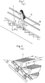
Further, an upstairs riding section of the escalator is constructed substantially in the same manner as the downstairs riding section mentioned before with reference to FIG. 5. In FIG. 6, therefore, individual elements of the upstairs riding section are denoted by reference numerals for their corresponding elements of the downstairs riding section shown in FIG. 5 with "'" suffixed thereto.
-
FIG. 7 is a general plan view showing the downstairs riding section of the escalator with the construction shown in FIG. 5 and the upstairs riding section with the construction shown in FIG. 6. Referring to FIG. 7, people who stand on the steps of the escalator and will not walk occupies the left-hand side of each step 1, while people who chose to walk the steps 1 of the escalator one after another walk on the right-hand side of each step 1. Accordingly, the leading handrail 1L is provided only on the right-hand side of the escalator, and not on the left-hand side. Except for the leading handrail 1L, the entire linkage-type transportation mechanism including the escalator and its relevant structures is symmetrical with respect to both longitudinal and transverse directions.
-
An encircled partial enlarged view of FIG. 7 shows the situation where the bridge 12B is interposed between the conveyor belt 107 of the first low-speed traveling mechanism 1S and the conveyor belt 108 of the second low-speed traveling mechanism 2S, comb-shaped projections formed at both ends of the bridge 12B meshing with a large number of grooves in the surface of each of the two conveyor belts 107 and 108, with the result that a gap is not produced between the conveyor belt 107, 108 and the bridge 12B.
-
In the above-described embodiments (2-1), (2-2) and (2-3), the linkage-type transportation mechanism having the highest traveling speed is an escalator. The present invention may, however, be applied even when a moving sidewalk (which has no inclined moving section) is substituted for the escalator. According to the foregoing embodiments, moreover, the escalator has a width allowing two persons to stand side by side on the tread of each step 1, and the leading handrail 1L is provided only on the right-hand side with respect to the traveling direction of the escalator. In the case where the escalator is designed for being capable of reversing the traveling direction of the escalator during use, however, the leading handrail 1L is provided on both the left-hand and right-hand sides of the escalator.
-
If the escalator's step 1 has tread width large enough for being occupied by only one person, and the leading handrail 1L is provided on both the left-hand and right-hand sides of the escalator, this enables a person to walk on the escalator with its lightweight baggage resting on one of the leading handrails.
-
According to the present invention, as described above, the transportation capacity of escalators and moving sidewalks having rigid treads can be improved. The weight of each step is substantially proportional to the square of its profile size, and the number of steps is inversely proportional to the profile size, so that the gross weight of all the steps is substantially proportional to the overall cross-sectional size of the steps. Thus, the cross section can be lessened, and the whole structure can be reduced in weight.