EP0683759B1 - Kontinuierliche kompostvorrichtung - Google Patents
Kontinuierliche kompostvorrichtung Download PDFInfo
- Publication number
- EP0683759B1 EP0683759B1 EP19930923428 EP93923428A EP0683759B1 EP 0683759 B1 EP0683759 B1 EP 0683759B1 EP 19930923428 EP19930923428 EP 19930923428 EP 93923428 A EP93923428 A EP 93923428A EP 0683759 B1 EP0683759 B1 EP 0683759B1
- Authority
- EP
- European Patent Office
- Prior art keywords
- tunnel
- tray
- trays
- conveyor
- garbage
- Prior art date
- Legal status (The legal status is an assumption and is not a legal conclusion. Google has not performed a legal analysis and makes no representation as to the accuracy of the status listed.)
- Expired - Lifetime
Links
- 238000009264 composting Methods 0.000 claims abstract description 37
- 239000007789 gas Substances 0.000 claims description 32
- 238000011144 upstream manufacturing Methods 0.000 claims description 25
- 238000005273 aeration Methods 0.000 claims description 15
- 239000000463 material Substances 0.000 claims description 8
- 238000000034 method Methods 0.000 claims description 7
- -1 polytetrafluoroethylene Polymers 0.000 claims description 3
- 229920001343 polytetrafluoroethylene Polymers 0.000 claims description 3
- 239000004810 polytetrafluoroethylene Substances 0.000 claims description 3
- 238000000151 deposition Methods 0.000 claims description 2
- 239000002184 metal Substances 0.000 claims description 2
- 230000003116 impacting effect Effects 0.000 claims 1
- 239000002361 compost Substances 0.000 abstract description 14
- 238000004064 recycling Methods 0.000 description 4
- 238000005276 aerator Methods 0.000 description 3
- QVGXLLKOCUKJST-UHFFFAOYSA-N atomic oxygen Chemical compound [O] QVGXLLKOCUKJST-UHFFFAOYSA-N 0.000 description 3
- 239000001301 oxygen Substances 0.000 description 3
- 229910052760 oxygen Inorganic materials 0.000 description 3
- 230000001580 bacterial effect Effects 0.000 description 2
- 230000009286 beneficial effect Effects 0.000 description 2
- 238000005056 compaction Methods 0.000 description 2
- 239000000203 mixture Substances 0.000 description 2
- 230000001473 noxious effect Effects 0.000 description 2
- 230000035943 smell Effects 0.000 description 2
- 230000007423 decrease Effects 0.000 description 1
- 230000003247 decreasing effect Effects 0.000 description 1
- 230000001627 detrimental effect Effects 0.000 description 1
- 230000000694 effects Effects 0.000 description 1
- 230000007613 environmental effect Effects 0.000 description 1
- DNJIEGIFACGWOD-UHFFFAOYSA-N ethanethiol Chemical compound CCS DNJIEGIFACGWOD-UHFFFAOYSA-N 0.000 description 1
- 238000001914 filtration Methods 0.000 description 1
- 230000005802 health problem Effects 0.000 description 1
- 230000002401 inhibitory effect Effects 0.000 description 1
- 230000001788 irregular Effects 0.000 description 1
- 230000000670 limiting effect Effects 0.000 description 1
- 230000002265 prevention Effects 0.000 description 1
- 230000000284 resting effect Effects 0.000 description 1
- 238000007789 sealing Methods 0.000 description 1
- 238000004513 sizing Methods 0.000 description 1
- 239000002341 toxic gas Substances 0.000 description 1
- 238000011179 visual inspection Methods 0.000 description 1
Images



Classifications
-
- C—CHEMISTRY; METALLURGY
- C05—FERTILISERS; MANUFACTURE THEREOF
- C05F—ORGANIC FERTILISERS NOT COVERED BY SUBCLASSES C05B, C05C, e.g. FERTILISERS FROM WASTE OR REFUSE
- C05F17/00—Preparation of fertilisers characterised by biological or biochemical treatment steps, e.g. composting or fermentation
- C05F17/90—Apparatus therefor
- C05F17/921—Devices in which the material is conveyed essentially horizontally between inlet and discharge means
- C05F17/936—Tunnels
-
- C—CHEMISTRY; METALLURGY
- C05—FERTILISERS; MANUFACTURE THEREOF
- C05F—ORGANIC FERTILISERS NOT COVERED BY SUBCLASSES C05B, C05C, e.g. FERTILISERS FROM WASTE OR REFUSE
- C05F17/00—Preparation of fertilisers characterised by biological or biochemical treatment steps, e.g. composting or fermentation
- C05F17/90—Apparatus therefor
- C05F17/964—Constructional parts, e.g. floors, covers or doors
-
- Y—GENERAL TAGGING OF NEW TECHNOLOGICAL DEVELOPMENTS; GENERAL TAGGING OF CROSS-SECTIONAL TECHNOLOGIES SPANNING OVER SEVERAL SECTIONS OF THE IPC; TECHNICAL SUBJECTS COVERED BY FORMER USPC CROSS-REFERENCE ART COLLECTIONS [XRACs] AND DIGESTS
- Y02—TECHNOLOGIES OR APPLICATIONS FOR MITIGATION OR ADAPTATION AGAINST CLIMATE CHANGE
- Y02P—CLIMATE CHANGE MITIGATION TECHNOLOGIES IN THE PRODUCTION OR PROCESSING OF GOODS
- Y02P20/00—Technologies relating to chemical industry
- Y02P20/141—Feedstock
- Y02P20/145—Feedstock the feedstock being materials of biological origin
-
- Y—GENERAL TAGGING OF NEW TECHNOLOGICAL DEVELOPMENTS; GENERAL TAGGING OF CROSS-SECTIONAL TECHNOLOGIES SPANNING OVER SEVERAL SECTIONS OF THE IPC; TECHNICAL SUBJECTS COVERED BY FORMER USPC CROSS-REFERENCE ART COLLECTIONS [XRACs] AND DIGESTS
- Y02—TECHNOLOGIES OR APPLICATIONS FOR MITIGATION OR ADAPTATION AGAINST CLIMATE CHANGE
- Y02W—CLIMATE CHANGE MITIGATION TECHNOLOGIES RELATED TO WASTEWATER TREATMENT OR WASTE MANAGEMENT
- Y02W30/00—Technologies for solid waste management
- Y02W30/40—Bio-organic fraction processing; Production of fertilisers from the organic fraction of waste or refuse
Definitions
- This invention relates to composters for garbage.
- composting has increased in importance.
- Various industrial and small scale composting systems have been developed to take the place of the traditional back-yard compost heap.
- Another example of such apparatus comprises a tunnel having a feed hopper above one end and an exit at the other end. At the feed end a ram is used at intervals to force the composting garbage through the tunnel over a stationary floor. The ram has a tendency to pack the garbage and thus inhibit aeration, which is necessary for successful composting.
- Another system of composting which does allow for the necessary aeration involves pulling composting garbage through a tunnel by means of a net.
- This system is a batch system and it is necessary to complete one batch of compost before starting another.
- Tunnel composters such as that described above merely vent the issuing gases.
- the present applicant has addressed the problem of providing a continuous composting system suitable for large or small scale use.
- he has addressed the problem of providing proper aeration, avoiding compaction of the composting garbage and inhibiting the unpleasant smells associated with composting.
- a continuous composter comprising: an enclosed elongate tunnel having a first end and a second end; an inlet for garbage in a top surface of the tunnel in the region of the first end; an outlet for compost in the second end; a conveyor track raised from a floor of the tunnel and extending along the length of the tunnel; a train of conveyor trays to travel shuntwise on the conveyor track, each tray having a shunting frame to receive directional shunting force and each tray having a foraminous carrier surface to allow aeration of material in the tray; a ram having a stroke in the direction of an elongate axis of the tunnel, the length of the stroke being equal to a chosen length of shunting step of the conveyor trays, the ram being located to act against the shunting frame of the conveyor tray which is furthest upstream.
- the tunnel may have generally parallel sidewalls and the conveyor track may comprise a pair of rails.
- a mixing hopper may be provided for garbage at the inlet.
- the mixing hopper may be arranged in said inlet to feed garbage into the conveyor tray which is furthest upstream.
- the conveyor trays may be generally rectangular in shape, and have a width between the shunting wall and an opposed wall equal to length of the ram stroke.
- the conveyor trays are provided with slide runners to bear on the conveyor track.
- the rails may have slide surfaces on which the trays may slide. It is, however, more convenient to provide these surfaces on the trays since they are more easily inspected for wear.
- the base of the conveyor trays may be perforated metal sheet or mesh or other foraminous material.
- Aeration means are suitably provided to feed air into a space between the tunnel floor and conveyor trays located on the conveyor track so that air rises through the bases of the trays and through material located thereon.
- Exhaust means are provided in a top surface of the tunnel to vent exhaust gases and spent aeration gases from the tunnel.
- Such mixing means may be provided in the tunnel for mixing composting garbage.
- Such mixing means may comprises mixing rollers extending from side to side of the tunnel and having, for example, paddles for mixing the garbage.
- the tunnel outlet may be provided with closure means openable by pressure of an advancing conveyor tray such as a freely hinged door.
- the invention also includes a method of composting comprising depositing garbage into a composting tunnel through an inlet in a top surface of the tunnel in the region of a first end into a tray located beneath the inlet being the furthest upstream tray of a train of trays on a track running longitudinally within the tunnel; moving the trays stepwise within the tunnel by operation of a ram against an upstream shunting surface of the furthest upstream tray, each step being equivalent to the width of a tray, whereby space is created upstream of the trays for location of a further upstream tray and a downstream tray is ejected from an outlet in a second end of the tunnel.
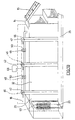
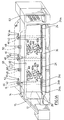
- the drawings illustrate a composter comprising a tunnel 12 having a top 13 and an input port 14 in an upstream end of top 13.
- a conveyor 15 lifts garbage to deliver it to input port 14.
- the downstream end 18 of tunnel 12 has a doorway 20 for outputting compost.
- tracks 22 are provided to each side of the tunnel supporting conveyor trays 24a - n.
- the conveyor trays 24 move stepwise through the tunnel in a longitudinal direction on the conveyor tracks.
- a conveyor tray 24 a is located on the tracks 22 underneath the mixing hopper 14. Garbage is added from the conveyor 15, through sliding door 17 to a suitable depth in tray 24 a , say within a foot of the roof of tunnel 12. The tray 24 a is then stepped forward by action of a ram 26 having a stroke sufficient to move tray 24 a forward sufficiently to allow space for a further tray 24 b . Ram 26 is then withdrawn and tray 24 b is inserted between the ram and tray 24 a .
- the number of trays and the length of the tunnel may be such that composting is complete when a tray 24 reaches end 18 of the tunnel.
- the compost may then be removed from the tray by a conveyor and the tray may be returned to the input end.
- Tray return may be manual or may be automated.
- each tray exiting from a tray exit port 20 may be ejected onto a conveyor to return the tray to a tray entry port.
- the size of the tunnel and the size of the trays may be such that each tray may take a day's supply of garbage. It is suggested that under good conditions of composting fourteen days will be sufficient to make compost and thus the line of conveyor trays within the composter may be fourteen as shown. The operation of the composter will be described in greater detail with reference to the apparatus parts hereinafter.
- Sliding door 17 is shown in more detail in Figure 6. Sliding may be conveniently in an upstream downstream direction in tracks 19 with closing being in the upstream direction. Whatever the direction of operation of door 17 it is found of operation of door 17 it is found convenient to taper it to narrow in the direction of closing. Tracks 19 are correspondingly tapered. As tapered door 17 closes in tapered tracks 19 it nests snugly into the tracks to make a tight seal. Rubber sealing means may also be provided.
- Each conveyor tray 24 comprises a frame 27 and foraminous surface 28 through which air can access the garbage to be composted.
- the foraminous surface 28 is located above frame 27.
- Trays are added to the train or trays at the upstream end of the tunnel 12 through a tray entry port.
- Tray 24 a which is acted upon by ram 26 to advance a step within the tunnel, acts on tray 24 b downstream of it to advance tray 24 b also.
- tray 24 b acts on tray 24 c .
- the trays are shunted down the tunnel until tray 24 n is shunted out of tray exit port 20. Since these trays are subject to considerable stresses, initially imparted from ram 26 against the frames 27, these frames 27 are built to withstand these stresses.
- Sidewalls 30 are of sufficient height to be impacted by the front face of ram 26.
- Ram 26 conveniently accesses the most upstream frame through the tray entry port. In practice, it is not necessary that walls 30 should be very high. It is only necessary that they have a vertical area to accommodate the driving face of ram 26 so as to absorb its whole force.
- the other pair of tray sidewalls 36 located longitudinally in the tunnel are conveniently made as sturdily sidewalls 32.
- these walls 36 do not have to absorb the full force of the ram against their planes. While considerable crumpling force may be exerted on them in movement of the trays along the tunnel, this force is somewhat mitigated by the presence of garbage in the tray.
- the frame 27 comprises two pairs of opposed sidewalls 30, and 36. One pair of these sidewalls 30 extend transversely across the tunnel 12 in upstream and downstream locations.
- Ram 26 impacts the upstream sidewall 30 a directly.
- Downstream sidewall 30b impacts the next upstream sidewall 30 a of tray 24 b .
- the trays 24 are shunted stepwise in a downstream direction by each stroke of ram 26.
- the opposed pair of sidewalls 36 run on tracks 22 carried by the walls 32 of tunnel 12.
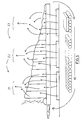
- the tracks 22 each comprise a U-section channel (see Figure 4), the web of which is attached to the respective tunnel wall 32.
- the web of track 22 is wide enough that the whole height of tray sidewalls 36 may be accommodated within the U-section while resting on carrier U-leg 37 a and covered by cover U-leg 37 b .
- the bottom of each tray sidewall 36 may conveniently be provided with a layer of polytetrafluoroethylene or other such material to reduce friction between the trays 24 and the carrier leg 37 a of channel 22.
- the tunnel 12 and the trays 24 may be sized according to the amount of garbage to be handled. Given that, under good conditions, composting may be achieved within fourteen days, it is convenient to provide one tray per day in the composter. Thus, if 200 pounds of garbage is to be handled per day, the tray size and tunnel size should be such that one tray will accept 200 pounds of garbage.
- the ram size and ram pressure must clearly also be suitably adjusted to moving the entire train of trays within the tunnel. It is, however, emphasized that a composter according to the invention may be designed for a very small domestic operation or for a very large industrial operation. The mechanics and engineering of tunnels and trays of suitable sizing are well within the scope of a man skilled in the art.
- the tunnel 12 is provided with various composting aids along its length. Such as aerators and mixers to loosen and rearrange the garbage. Moreover, means may be provided to recycle at least some of the gases produced during composting, thereby filtering and reducing the total amount of unpleasant, noxious gas.
- each aerator 40 comprises a vertical duct 42 extending downwardly outside the tunnel 12 adjacent to sidewall 32.
- the duct 42 draws air from the exterior through an inlet pipe 44 by means of a fan 46. This air is transported down the duct to below the level of the conveyor trays 24 into a header in the respective zone Z1, Z2, or Z3. From each header the air is distributed through composting garbage in the respective zone.
- a further fan 48 may be provided at the bottom of the duct 42.
- Exhaust ducting 48 a , b , c is provided at the top of the tunnel in each zone for the removal of the air and gases produced during composting.
- the exhaust gases contain an appreciable amount of unused oxygen, and it is possible that, apart from the addition of oxygen, one affect of recycling the exhaust gases is to enhance the lightening effect of the aeration and to help prevention and compaction of the garbage.
- Another important benefit of using recycled exhaust gases is that the exhaust gases are heated due to the bacterial action in the garbage.
- zone 1 where the garbage is fresh and cool, it is possible to use aerating gas which may be as much as 100% recycled exhaust gas. This may help to heat up the garbage to optimum composting temperature.
- zone Z3 where bacterial action is substantial, the composting garbage is warm and it may be beneficial to use as much as 100% cool, fresh air to maintain the temperature of the composting process at its optimum.
- the aerating gas may include as much oxygen as possible for maximum composting. As the composting progresses the proportion of recycled gas varies depending on the length of the composting period and the composition of the garbage.
- zones may be used in apparatus according to the invention, and the description relating to three zones is exemplary only.
- mixing rollers 60 may be provided extending across the tunnel 12. These mixing rollers 60 may extend from sidewall to sidewall of the tunnel 12 and may have drive shafts extending through the side of the tunnel to be powered by any convenient means (not shown). As illustrated, two mixing rollers, 60 a and 60 b are provided one above the other, in the end region of zone Z1, and in the end region of zone Z2. However, it will be appreciated that mixing rollers can be provided at whatever distances along the tunnel are thought suitable.
- the mixing rollers may be of any suitable form and, indeed, need not be rollers but may be any device to mix the compost. As illustrated, the rollers 60 are provided with paddles to catch and circulate the garbage. The mixing rollers 60 may rotate on a drive shafts in similar or opposed directions.
- zone Z3 At the end of zone Z3, three augers 63 are provided one above the other to transport the formed compost into a side tunnel annex. In the annex the compost delivered from the augers falls onto a conveyor and is removed through a sliding door.
- Computer 68 calculates and controls the proportions of exhaust gas and fresh aerating gas delivered into each of the zones Z1, Z2 and Z3, and may also control opening and closing of the sliding doors. Generally, the sliding doors are only permitted to open when conveyors 20 and respectively are in operation. At all other times, the tunnel is effectively completely sealed.
- the entry port is provided for the trays 24 and an exit port 20 is also provided; but, when trays 24 are in position within the tunnel 12, the frames effectively block and close the entry and exit ports for the trays.
- the computer 68 may also ensure that the pressure of aerating gas, with or without an exhaust gas component, is maintained lower than the suction pressure removing exhaust gas. If the pressure within the tunnel is maintained less than the atmospheric pressure, any leaks in the system will not result in the escape of noxious odours.
- tray 24 a is loaded to within, perhaps, one foot of the roof of tunnel 12. This volume may have decreased to 40% of the original by the time the tray has reached the position of tray 24n. It may be possible by use of the mixers, or by use of additional augers acting longitudinally, to provide some mixing of material from tray to tray without detriment to the composting process. Such mixing may help to move material to maintain a more even level in the tunnel. At least, additional mixing may provide greater aeration and lift and hasten composting in the downstream trays.
- the longitudinal and volume dimensions of the tunnel are purely a matter of choice. It is for convenience that the system has been described with reference to a tunnel of length to accommodate fourteen trays, one tray being utilized for each day's garbage. If a regular supply of garbage is available, this system is of convenience to the operator irrespective of the amount of garbage being delivered per day. Thus, if an operator can rely on say, 90 kilos (200 pounds) of garbage per day, the system may be designed so that each tray will accommodate 90 kilos (200 pounds) of garbage. In such a system there is little need to check whether a tray is being overloaded and whether it is time to install a new tray.
- the choice of fourteen days (or fourteen trays) as the length of the tunnel is by no means limiting. Under good conditions compost may be made in fourteen days, but given suitable strength of trays and suitable force of the ram there is no objection to compost remaining in the tunnel for a greater length of time. This will, of course, extend the length of the tunnel beyond that minimally necessary.
Landscapes
- Chemical & Material Sciences (AREA)
- Chemical Kinetics & Catalysis (AREA)
- Life Sciences & Earth Sciences (AREA)
- Engineering & Computer Science (AREA)
- Biochemistry (AREA)
- Biotechnology (AREA)
- Health & Medical Sciences (AREA)
- General Chemical & Material Sciences (AREA)
- Microbiology (AREA)
- Molecular Biology (AREA)
- Organic Chemistry (AREA)
- Fertilizers (AREA)
- Processing Of Solid Wastes (AREA)
- Preparation Of Compounds By Using Micro-Organisms (AREA)
Claims (17)
- Kontinuierliche Kompostieranlage bestehend aus: einem umschlossenen, langgestreckten Tunnel (12), das ein erstes Ende und ein zweites Ende aufweist; einem Einlaß (14) für Abfall in einer Oberseite des Tunnels im Bereich des ersten Endes; Schienen (22), die sich ab einem Boden des Tunnels erheben und sich entlang der Länge des Tunnels erstrecken; einer Vielheit allgemein rechteckiger Förderbleche (24); und einer Ramme (26, um für richtungsabhängige Verschiebekraft in Längsrichtung des Tunnels zu sorgen, dadurch gekennzeichnet, daß: jedes Blech eine Verschiebewand (30a) und eine Gegenwand (30b) hat, um rangierartig auf den Schienen ab dem stromaufwärts Ende zu gleiten, wobei die Verschiebewand Teil eines Verschieberahmens (27) ist, um Verschiebekraft zu empfangen und wobei jedes Blech eine poröse Tragoberfläche (28) aufweist; und die Ramme (26) einen Hub an dem stromaufwärts gelegenen Ende gegen das stromabwärts gelegene Ende des Tunnels (12) ausübt, die Hublänge entspricht dabei der Breite des Förderblechs (24) zwischen der Verschiebewand (30a) und der Gegenwand (30b), die Ramme ist positioniert, um gegen die Verschiebewand (30a) des Förderblechs (24) zu wirken, das sich auf weitesten stromaufwärts befindet.
- Kontinuierliche Kompostieranlage nach Anspruch 1, in der das Tunnel (12) im allgemeinen parallele Seitenwände (32) aufweist und die Schienen (22) ein Schienenpaar sind, wovon jede ein U-Profil umfaßt, das durch seine Versteifung mit einer Seitenwand (32) verbunden ist und jedes U-Profil einen Tragschenkel (37a), der die Bleche trägt und einen Schenkel (37b) aufweist, der sich über einen Seitenrand der Rahmen dieser Bleche erstreckt.
- Kontinuierliche Kompostieranlage nach Anspruch 2, in der eine Schicht Polytetrafluorethylen zwischen einem Boden (28) jedes Blechs (24) und dem Tragschenkel (37a ) vorgesehen ist.
- Kontinuierliche Kompostieranlage nach Anspruch 3, in der die Polytetrafluorethylenschicht am Boden (28) jedes Blechs (24) befestigt ist.
- Kontinuierliche Kompostieranlage nach Anspruch 1, in der Einlaß (24) mit einer Schiebetür (17) versehen ist.
- Kontinuierliche Kompostieranlage nach Anspruch 5, in der die Schiebetür (17) in der Verschlußrichtung verjüngt ist und in einer entsprechend verjüngten Führungsbahn (19) läuft, um Abfall in das Förderblech (24) zu speisen, das sich am weitesten stromaufwärts befindet.
- Kontinuierliche Kompostieranlage nach Anspruch 6, in der eine Dichtung für die Tür (17) vorgesehen ist.
- Kontinuierliche Kompostieranlage nach Anspruch 1, in der ein Förderer vorgesehen ist, um Förderbleche (24) ab dem stromabwärts gelegenen Ende zum stromaufwärts gelegenen Ende zu retournieren.
- Kontinuierliche Kompostieranlage nach Anspruch 1, in der die Förderbleche mit poröser Tragoberfläche (28) aus perforiertem Blech sind.
- Kontinuierliche Kompostieranlage nach Anspruch 1, in der das poröse Tragblech (28) der Förderbleche aus Drahtnetz besteht.
- Kontinuierliche Kompostieranlage nach Anspruch 1, in der Belüftung vorgesehen ist, um Luft in einen Raum zwischen dem Tunnelboden und den Förderblechen (24) zu speisen, die sich auf der Förderbahn befinden.
- Kontinuierliche Kompostieranlage nach Anspruch 11, in der Entlüftungsmittel (48) in einer oberen Fläche des Tunnels vorgesehen sind, um Abgase und verbrauchte Belüftungsgase aus dem Tunnel zu entlüften, die Entlüftungsmittel schließen Mittel ein, um einen Teil der Abgase und der verbrauchten Entlüftungsgase in genannte Belüftungsmittel zu recyceln, und in der Computermittel (68) vorgesehen sind, um das Verhältnis der Abgase und des verbrauchten Belüftungsgases zu frischem Belüftungsgas zu überwachen.
- Kontinuierliche Kompostieranlage nach Anspruch 1, in der Mischmittel (60) im Tunnel zum Mischen des auf den Blechen (24) positionierten Abfalls vorgesehen sind, wobei die Mischmittel (60) Mischwalzen umfassen, die sich zwischen Seitenwänden (32) des Tunnels erstrecken.
- Kontinuierliche Kompostieranlage nach Anspruch 13, in der die Mischwalzen (60) mit Mischpaddeln versehen sind.
- Kontinuierliche Kompostieraniage nach Anspruch 1, in der Förderschnecken (63) in einem stromabwärts gelegenen Bereich des Tunnels vorgesehen sind, um kompostiertes Material ab dort zu transportieren.
- Kontinuierliche Kompostieranlage nach Anspruch 1, in der vierzehn Förderbleche (24) vorgesehen sind.
- Verfahren für kontinuierliches Kompostieren, das einbezieht: Deponieren von Abfall in ein Kompostiertunnel (12) durch einen Einlaß (14) in einer oberen Oberfläche des Tunnels im Bereich eines ersten Endes auf ein Blech (24), das unter dem Einlaß positioniert ist, welches das am weitesten stromaufwärts gelegene Blech eines Strangs von Blechen auf einer Führungsbahn (22) ist, die in Längsrichtung innerhalb des Tunnels (12) verläuft; Bewegen der Bleche (24) innerhalb des Tunnels (12) durch Betätigung einer Ramme (26), dadurch gekennzeichnet, daß: die Betätigung der Ramme (26) dazu dient Bleche (24) schrittweise durch Schlagen auf eine stromaufwärts gelegene Verschiebefläche (30a) des am weitesten stromaufwärts gelegenen Blechs (24) zu bewegen, wobei jeder Schritt der Breite eines Blechs entspricht, wodurch stromaufwärts der Bleche Platz zum Positionieren eines weiteren stromaufwärts gelegenen Blechs geschaffen wird und ein stromabwärts gelegenes Blech wird aus einem Auslaß in einem zweiten Ende des Tunnels ausgestoßen.
Applications Claiming Priority (4)
| Application Number | Priority Date | Filing Date | Title |
|---|---|---|---|
| CA 2089305 CA2089305C (en) | 1993-02-11 | 1993-02-11 | Continuous composter |
| CA2089305 | 1993-02-11 | ||
| US08/017,613 US5409831A (en) | 1993-02-11 | 1993-02-12 | Continuous composter |
| PCT/CA1993/000446 WO1994018143A1 (en) | 1993-02-11 | 1993-10-19 | Continuous composter |
Publications (2)
| Publication Number | Publication Date |
|---|---|
| EP0683759A1 EP0683759A1 (de) | 1995-11-29 |
| EP0683759B1 true EP0683759B1 (de) | 1997-11-26 |
Family
ID=25675889
Family Applications (1)
| Application Number | Title | Priority Date | Filing Date |
|---|---|---|---|
| EP19930923428 Expired - Lifetime EP0683759B1 (de) | 1993-02-11 | 1993-10-19 | Kontinuierliche kompostvorrichtung |
Country Status (14)
| Country | Link |
|---|---|
| US (1) | US5409831A (de) |
| EP (1) | EP0683759B1 (de) |
| JP (1) | JP3441731B2 (de) |
| CN (2) | CN1103753C (de) |
| AT (1) | ATE160559T1 (de) |
| AU (1) | AU677971B2 (de) |
| BR (1) | BR9307848A (de) |
| CA (1) | CA2089305C (de) |
| DE (1) | DE69315446T2 (de) |
| DK (1) | DK0683759T3 (de) |
| ES (1) | ES2111189T3 (de) |
| GR (1) | GR3026012T3 (de) |
| NZ (1) | NZ257086A (de) |
| WO (1) | WO1994018143A1 (de) |
Families Citing this family (24)
| Publication number | Priority date | Publication date | Assignee | Title |
|---|---|---|---|---|
| DK136193A (da) * | 1993-12-06 | 1995-06-28 | Vagn Bislev | Komposteringsanlæg til organisk affald, samt fremgangsmåde ved kompostering af sådant affald |
| WO1995020554A1 (en) * | 1994-01-31 | 1995-08-03 | James Wright | Continuous composter |
| US5583045A (en) * | 1995-01-30 | 1996-12-10 | Bedminster Bioconversion Corporation | Compost curing and odor control system |
| US6627434B1 (en) | 1995-11-13 | 2003-09-30 | Mcnelly James J. | Method and apparatus for controlled composting and bioremediating |
| US6281001B1 (en) | 1995-11-13 | 2001-08-28 | Mcnelly James J. | Process for controlled composting of organic material and for bioremediating soils |
| NZ325635A (en) * | 1995-12-15 | 1999-08-30 | Bedminster Bioconversion Corp | Air floor grating |
| US5846815A (en) * | 1997-05-13 | 1998-12-08 | Wright; James | Continuous composter having self contained aerating zones |
| FR2820421A1 (fr) * | 2001-02-05 | 2002-08-09 | Recyval Sa | Conteneur automatique de compostage de produits organiques |
| US6560895B1 (en) | 2001-12-10 | 2003-05-13 | Willard Clark | Chicken manure processing apparatus |
| US6766592B1 (en) | 2001-12-10 | 2004-07-27 | Willard Clark | Chicken manure processing apparatus |
| WO2007062520A1 (en) * | 2005-12-01 | 2007-06-07 | James Wright | Method and apparatus for drying organic material |
| CA2683202A1 (en) | 2006-04-07 | 2007-10-18 | James J. Mcnelly | Dual purpose intermodal and bioconversion container |
| US20080022739A1 (en) * | 2006-07-26 | 2008-01-31 | Prakash Aswani | Vertical composter with leachate retention system |
| US20110104795A1 (en) * | 2009-10-30 | 2011-05-05 | Terra-Gro, Inc. | Compost Turning and Aerating Machine |
| US20120121239A1 (en) * | 2010-11-17 | 2012-05-17 | Kompoferm Gmbh | Device for processing substances, in particular digestate and digestate mixtures |
| CN102115345A (zh) * | 2010-12-02 | 2011-07-06 | 北京工商大学 | 一套食品垃圾移动式高效好氧堆肥工艺 |
| US8685716B2 (en) | 2011-05-10 | 2014-04-01 | Great Wall Of China Waste Company Inc. | Composting apparatus and method |
| CN103694008B (zh) * | 2013-11-25 | 2015-12-30 | 广西金穗农业集团有限公司 | 有机肥料液化方法 |
| CN104609908B (zh) * | 2015-01-27 | 2017-05-31 | 新疆金天昆环境科技有限公司 | 一种利用油烟强化餐厨垃圾微生物堆肥的方法及装置 |
| CN106140776A (zh) * | 2015-03-24 | 2016-11-23 | 英普(北京)环境科技有限公司 | 一种有机废弃物好氧发酵方法及设备 |
| CN105665426A (zh) * | 2016-04-10 | 2016-06-15 | 周栋 | 一种农村生活垃圾处理装置 |
| US12275678B2 (en) * | 2016-11-30 | 2025-04-15 | Greenscience Technologies Inc. | Vermicast production through conversion of biodegradable organic matter |
| US11111188B2 (en) | 2017-10-23 | 2021-09-07 | Timothy G. Shuttleworth | Container-based composting |
| NL2029597B1 (nl) * | 2021-11-02 | 2023-06-01 | Valoriworld B V | Dynamische actieve beladings- en beluchtingsvloer voor het composteren van organisch materiaal in een gesloten mobiele of stationaire reactor. |
Family Cites Families (15)
| Publication number | Priority date | Publication date | Assignee | Title |
|---|---|---|---|---|
| US1545185A (en) * | 1924-05-31 | 1925-07-07 | Oscar W Hancock | Fruit drier |
| FR1302793A (fr) * | 1961-10-06 | 1962-08-31 | Compost Engineers Ltd | Perfectionnements au traitement de matériaux organiques pulvérisés |
| SU543667A1 (ru) * | 1974-10-01 | 1977-01-25 | Государственный Проектно-Изыскательский Институт Микробиологической Промышленности "Южгипробиосинтез" | Аппарат дл непрерывного выращивани микроорганизмов |
| US4326874A (en) * | 1978-03-13 | 1982-04-27 | Buerklin Werner | Process and apparatus for preparing compostable material |
| FR2495887A2 (fr) * | 1980-12-12 | 1982-06-18 | Nayet Roger | Digesteur horizontal mixte, en vue de la production continue de gaz methane |
| JPS57209895A (en) * | 1981-06-15 | 1982-12-23 | Cubic Eng Kk | Composting device |
| US4414335A (en) * | 1981-12-23 | 1983-11-08 | Paygro, Inc. | Composting system with movable process cars |
| NL8202737A (nl) * | 1982-07-07 | 1984-02-01 | Suiker Unie | Werkwijze en inrichting voor het anaeroob hydrolyseren en verzuren van plantaardig materiaal. |
| JPS5950089A (ja) * | 1982-09-09 | 1984-03-22 | 日立化成工業株式会社 | 連続堆肥化装置 |
| IT1203711B (it) * | 1983-10-18 | 1989-02-15 | Secit Spa | Impianto per il trattamento dei rifiuti e dei fanghi biologici |
| US4798802A (en) * | 1987-07-28 | 1989-01-17 | Ryan Richard M | Method for accelerating composting of organic matter and composting reactor therefor |
| US5023178A (en) * | 1988-12-16 | 1991-06-11 | Ashbrook-Simon-Hartley Corporation | Composting method and apparatus utilizing air assist to aid in movement of organic matter |
| US5049486A (en) * | 1989-04-14 | 1991-09-17 | Ashbrook-Simon-Hartley Corporation | Temperature monitoring apparatus and method in a composting system through which organic matter is moved to effect composting |
| AU3380195A (en) * | 1994-09-06 | 1996-03-27 | Per Eduard Robert Bjerager | Plant and method for cleaning and cooling of recirculated air during composting and use of such a plant or method |
| US5591635A (en) * | 1994-10-14 | 1997-01-07 | Dbs Manufacturing, Inc. | Methods and apparatuses for rapid composting with closed air loop circulation for positive control |
-
1993
- 1993-02-11 CA CA 2089305 patent/CA2089305C/en not_active Expired - Lifetime
- 1993-02-12 US US08/017,613 patent/US5409831A/en not_active Expired - Lifetime
- 1993-10-19 NZ NZ257086A patent/NZ257086A/en not_active IP Right Cessation
- 1993-10-19 WO PCT/CA1993/000446 patent/WO1994018143A1/en not_active Ceased
- 1993-10-19 AU AU53325/94A patent/AU677971B2/en not_active Ceased
- 1993-10-19 JP JP51746394A patent/JP3441731B2/ja not_active Expired - Fee Related
- 1993-10-19 DK DK93923428T patent/DK0683759T3/da active
- 1993-10-19 BR BR9307848A patent/BR9307848A/pt not_active IP Right Cessation
- 1993-10-19 AT AT93923428T patent/ATE160559T1/de not_active IP Right Cessation
- 1993-10-19 EP EP19930923428 patent/EP0683759B1/de not_active Expired - Lifetime
- 1993-10-19 ES ES93923428T patent/ES2111189T3/es not_active Expired - Lifetime
- 1993-10-19 DE DE69315446T patent/DE69315446T2/de not_active Expired - Lifetime
-
1994
- 1994-02-09 CN CN94102784A patent/CN1103753C/zh not_active Expired - Lifetime
-
1998
- 1998-01-28 GR GR980400182T patent/GR3026012T3/el unknown
-
2003
- 2003-01-10 CN CNB031015468A patent/CN1232478C/zh not_active Expired - Fee Related
Also Published As
| Publication number | Publication date |
|---|---|
| DK0683759T3 (da) | 1998-04-27 |
| GR3026012T3 (en) | 1998-04-30 |
| EP0683759A1 (de) | 1995-11-29 |
| CN1439622A (zh) | 2003-09-03 |
| CN1232478C (zh) | 2005-12-21 |
| ATE160559T1 (de) | 1997-12-15 |
| CA2089305A1 (en) | 1994-08-12 |
| AU677971B2 (en) | 1997-05-15 |
| CN1103753C (zh) | 2003-03-26 |
| WO1994018143A1 (en) | 1994-08-18 |
| CN1099370A (zh) | 1995-03-01 |
| JP3441731B2 (ja) | 2003-09-02 |
| CA2089305C (en) | 1998-02-03 |
| BR9307848A (pt) | 1996-02-06 |
| DE69315446D1 (de) | 1998-01-08 |
| DE69315446T2 (de) | 1998-04-02 |
| JPH08506792A (ja) | 1996-07-23 |
| US5409831A (en) | 1995-04-25 |
| ES2111189T3 (es) | 1998-03-01 |
| AU5332594A (en) | 1994-08-29 |
| NZ257086A (en) | 1996-12-20 |
| HK1055938A1 (en) | 2004-01-30 |
Similar Documents
| Publication | Publication Date | Title |
|---|---|---|
| AU677971B2 (en) | Continuous composter | |
| US4798802A (en) | Method for accelerating composting of organic matter and composting reactor therefor | |
| FI67685C (fi) | Foerfarande foer aerobisk foermultning av organiska avfallsaemnen eller foer aotminstone delvis foerkoksning av organiska avfallsaemnen i foermultningsbehaollare samt anordning foer genomfoerande av foerfarandet | |
| US5846815A (en) | Continuous composter having self contained aerating zones | |
| US5942022A (en) | Composting plant for organic waste and method for composting such waste | |
| JPH039800B2 (de) | ||
| US5551969A (en) | Continuous composter | |
| WO2008014369A2 (en) | Vertical composter with leachate retention system | |
| JP2007283303A (ja) | 有機廃棄物処理方法および設備 | |
| JPS637111B2 (de) | ||
| WO1995020554A1 (en) | Continuous composter | |
| KR100360808B1 (ko) | 유기성 폐기물 처리를 위한 웜진 | |
| JP2005538023A (ja) | 処理領域を備えた直立式堆肥化装置 | |
| JP2000063190A (ja) | 発酵堆肥化装置 | |
| MXPA99010290A (en) | Continuous composter having self-contained aeration zones | |
| CN216141435U (zh) | 一种养殖粪便发酵处理系统 | |
| HK1055938B (en) | Continuous composter | |
| JP2001278687A (ja) | 生ごみ処理装置 | |
| JPWO1999030846A1 (ja) | 有機廃棄物処理方法および設備 | |
| CZ401299A3 (cs) | Kompostovací zařízení s nepřetržitým provozem se samostatnými provzdušňovacími zónami | |
| JPS6341874B2 (de) | ||
| JPH11114544A (ja) | 有機質材料の発酵処理方法および発酵処理装置 | |
| JP2001017998A (ja) | 有機廃棄物処理設備 | |
| JPS5912628B2 (ja) | 堆肥化方法及びその装置 | |
| JPS60108391A (ja) | 堆肥化方法並びに装置 |
Legal Events
| Date | Code | Title | Description |
|---|---|---|---|
| PUAI | Public reference made under article 153(3) epc to a published international application that has entered the european phase |
Free format text: ORIGINAL CODE: 0009012 |
|
| 17P | Request for examination filed |
Effective date: 19950812 |
|
| AK | Designated contracting states |
Kind code of ref document: A1 Designated state(s): AT BE CH DE DK ES FR GB GR IE IT LI LU MC NL PT SE |
|
| 17Q | First examination report despatched |
Effective date: 19960423 |
|
| GRAG | Despatch of communication of intention to grant |
Free format text: ORIGINAL CODE: EPIDOS AGRA |
|
| GRAH | Despatch of communication of intention to grant a patent |
Free format text: ORIGINAL CODE: EPIDOS IGRA |
|
| GRAH | Despatch of communication of intention to grant a patent |
Free format text: ORIGINAL CODE: EPIDOS IGRA |
|
| GRAA | (expected) grant |
Free format text: ORIGINAL CODE: 0009210 |
|
| ITF | It: translation for a ep patent filed | ||
| AK | Designated contracting states |
Kind code of ref document: B1 Designated state(s): AT BE CH DE DK ES FR GB GR IE IT LI LU MC NL PT SE |
|
| REF | Corresponds to: |
Ref document number: 160559 Country of ref document: AT Date of ref document: 19971215 Kind code of ref document: T |
|
| REG | Reference to a national code |
Ref country code: CH Ref legal event code: EP |
|
| REF | Corresponds to: |
Ref document number: 69315446 Country of ref document: DE Date of ref document: 19980108 |
|
| ET | Fr: translation filed | ||
| PG25 | Lapsed in a contracting state [announced via postgrant information from national office to epo] |
Ref country code: SE Free format text: LAPSE BECAUSE OF FAILURE TO SUBMIT A TRANSLATION OF THE DESCRIPTION OR TO PAY THE FEE WITHIN THE PRESCRIBED TIME-LIMIT Effective date: 19980226 |
|
| REG | Reference to a national code |
Ref country code: ES Ref legal event code: FG2A Ref document number: 2111189 Country of ref document: ES Kind code of ref document: T3 |
|
| REG | Reference to a national code |
Ref country code: DK Ref legal event code: T3 |
|
| REG | Reference to a national code |
Ref country code: CH Ref legal event code: AEN Free format text: LA POURSUITE DE LA PROCEDURE REQUISE LE 06.04.1998 A ETE ACCORDEE. LE BREVET EST REACTIVE. |
|
| REG | Reference to a national code |
Ref country code: PT Ref legal event code: SC4A Free format text: AVAILABILITY OF NATIONAL TRANSLATION Effective date: 19980423 |
|
| PLBE | No opposition filed within time limit |
Free format text: ORIGINAL CODE: 0009261 |
|
| STAA | Information on the status of an ep patent application or granted ep patent |
Free format text: STATUS: NO OPPOSITION FILED WITHIN TIME LIMIT |
|
| 26N | No opposition filed | ||
| PGFP | Annual fee paid to national office [announced via postgrant information from national office to epo] |
Ref country code: MC Payment date: 19991015 Year of fee payment: 7 |
|
| PGFP | Annual fee paid to national office [announced via postgrant information from national office to epo] |
Ref country code: LU Payment date: 19991027 Year of fee payment: 7 |
|
| PG25 | Lapsed in a contracting state [announced via postgrant information from national office to epo] |
Ref country code: LU Free format text: LAPSE BECAUSE OF NON-PAYMENT OF DUE FEES Effective date: 20001019 |
|
| PG25 | Lapsed in a contracting state [announced via postgrant information from national office to epo] |
Ref country code: MC Free format text: THE PATENT HAS BEEN ANNULLED BY A DECISION OF A NATIONAL AUTHORITY Effective date: 20001031 |
|
| REG | Reference to a national code |
Ref country code: GB Ref legal event code: IF02 |
|
| NLS | Nl: assignments of ep-patents |
Owner name: 1207974 ONTARIO LTD. |
|
| REG | Reference to a national code |
Ref country code: CH Ref legal event code: PUE Owner name: 1207974 ONTARIO LTD. Free format text: WRIGHT, JAMES#511 WOODLANDS ACRES CRESCENT, R.R. 2#MAPLE, ONTARIO L6A 1G2 (CA) -TRANSFER TO- 1207974 ONTARIO LTD.#SUITE 300 950 YONGE STREET#RICHMOND HILL, ONTARIO L4C 9S6 (CA) |
|
| REG | Reference to a national code |
Ref country code: PT Ref legal event code: PC4A Free format text: 1207974 ONTARIO LTD. CA Effective date: 20040213 |
|
| REG | Reference to a national code |
Ref country code: FR Ref legal event code: TP |
|
| REG | Reference to a national code |
Ref country code: ES Ref legal event code: PC2A |
|
| REG | Reference to a national code |
Ref country code: GB Ref legal event code: 732E |
|
| REG | Reference to a national code |
Ref country code: CH Ref legal event code: PCAR Free format text: ISLER & PEDRAZZINI AG;POSTFACH 1772;8027 ZUERICH (CH) |
|
| REG | Reference to a national code |
Ref country code: PT Ref legal event code: MM4A Free format text: LAPSE DUE TO NON-PAYMENT OF FEES Effective date: 20090420 |
|
| REG | Reference to a national code |
Ref country code: PT Ref legal event code: NF4A Free format text: RESTITUTIO IN INTEGRUM Effective date: 20090505 |
|
| PGFP | Annual fee paid to national office [announced via postgrant information from national office to epo] |
Ref country code: DK Payment date: 20090430 Year of fee payment: 16 |
|
| PG25 | Lapsed in a contracting state [announced via postgrant information from national office to epo] |
Ref country code: IT Free format text: LAPSE BECAUSE OF NON-PAYMENT OF DUE FEES Effective date: 20081019 |
|
| PGFP | Annual fee paid to national office [announced via postgrant information from national office to epo] |
Ref country code: PT Payment date: 20090505 Year of fee payment: 16 Ref country code: AT Payment date: 20090430 Year of fee payment: 16 |
|
| PGRI | Patent reinstated in contracting state [announced from national office to epo] |
Ref country code: PT Effective date: 20090505 |
|
| PGFP | Annual fee paid to national office [announced via postgrant information from national office to epo] |
Ref country code: BE Payment date: 20090608 Year of fee payment: 16 |
|
| PGFP | Annual fee paid to national office [announced via postgrant information from national office to epo] |
Ref country code: CH Payment date: 20090430 Year of fee payment: 16 |
|
| PGFP | Annual fee paid to national office [announced via postgrant information from national office to epo] |
Ref country code: GR Payment date: 20090430 Year of fee payment: 16 |
|
| REG | Reference to a national code |
Ref country code: PT Ref legal event code: MM4A Free format text: LAPSE DUE TO NON-PAYMENT OF FEES Effective date: 20100419 |
|
| BERE | Be: lapsed |
Owner name: *1207974 ONTARIO LTD Effective date: 20091031 |
|
| REG | Reference to a national code |
Ref country code: CH Ref legal event code: PL |
|
| REG | Reference to a national code |
Ref country code: DK Ref legal event code: EBP |
|
| PG25 | Lapsed in a contracting state [announced via postgrant information from national office to epo] |
Ref country code: PT Free format text: LAPSE BECAUSE OF NON-PAYMENT OF DUE FEES Effective date: 20100419 |
|
| PGFP | Annual fee paid to national office [announced via postgrant information from national office to epo] |
Ref country code: FR Payment date: 20100521 Year of fee payment: 17 Ref country code: ES Payment date: 20100429 Year of fee payment: 17 |
|
| PG25 | Lapsed in a contracting state [announced via postgrant information from national office to epo] |
Ref country code: AT Free format text: LAPSE BECAUSE OF NON-PAYMENT OF DUE FEES Effective date: 20091019 |
|
| PGFP | Annual fee paid to national office [announced via postgrant information from national office to epo] |
Ref country code: NL Payment date: 20100429 Year of fee payment: 17 Ref country code: DE Payment date: 20100430 Year of fee payment: 17 |
|
| PGRI | Patent reinstated in contracting state [announced from national office to epo] |
Ref country code: IT Effective date: 20100801 |
|
| PG25 | Lapsed in a contracting state [announced via postgrant information from national office to epo] |
Ref country code: LI Free format text: LAPSE BECAUSE OF NON-PAYMENT OF DUE FEES Effective date: 20091031 Ref country code: GR Free format text: LAPSE BECAUSE OF NON-PAYMENT OF DUE FEES Effective date: 20100504 Ref country code: CH Free format text: LAPSE BECAUSE OF NON-PAYMENT OF DUE FEES Effective date: 20091031 Ref country code: BE Free format text: LAPSE BECAUSE OF NON-PAYMENT OF DUE FEES Effective date: 20091031 |
|
| PG25 | Lapsed in a contracting state [announced via postgrant information from national office to epo] |
Ref country code: DK Free format text: LAPSE BECAUSE OF NON-PAYMENT OF DUE FEES Effective date: 20091031 |
|
| PGRI | Patent reinstated in contracting state [announced from national office to epo] |
Ref country code: IT Effective date: 20100801 |
|
| REG | Reference to a national code |
Ref country code: NL Ref legal event code: V1 Effective date: 20110501 |
|
| PG25 | Lapsed in a contracting state [announced via postgrant information from national office to epo] |
Ref country code: FR Free format text: LAPSE BECAUSE OF NON-PAYMENT OF DUE FEES Effective date: 20101102 |
|
| PGFP | Annual fee paid to national office [announced via postgrant information from national office to epo] |
Ref country code: IE Payment date: 20110429 Year of fee payment: 18 Ref country code: IT Payment date: 20100430 Year of fee payment: 17 |
|
| PGRI | Patent reinstated in contracting state [announced from national office to epo] |
Ref country code: IT Effective date: 20110616 |
|
| REG | Reference to a national code |
Ref country code: FR Ref legal event code: ST Effective date: 20110630 |
|
| REG | Reference to a national code |
Ref country code: DE Ref legal event code: R119 Ref document number: 69315446 Country of ref document: DE Effective date: 20110502 |
|
| PG25 | Lapsed in a contracting state [announced via postgrant information from national office to epo] |
Ref country code: NL Free format text: LAPSE BECAUSE OF NON-PAYMENT OF DUE FEES Effective date: 20110501 |
|
| PGFP | Annual fee paid to national office [announced via postgrant information from national office to epo] |
Ref country code: GB Payment date: 20110428 Year of fee payment: 18 |
|
| REG | Reference to a national code |
Ref country code: ES Ref legal event code: FD2A Effective date: 20111118 |
|
| PGRI | Patent reinstated in contracting state [announced from national office to epo] |
Ref country code: IT Effective date: 20110616 |
|
| PG25 | Lapsed in a contracting state [announced via postgrant information from national office to epo] |
Ref country code: ES Free format text: LAPSE BECAUSE OF NON-PAYMENT OF DUE FEES Effective date: 20101020 |
|
| GBPC | Gb: european patent ceased through non-payment of renewal fee |
Effective date: 20111019 |
|
| REG | Reference to a national code |
Ref country code: IE Ref legal event code: MM4A |
|
| PG25 | Lapsed in a contracting state [announced via postgrant information from national office to epo] |
Ref country code: GB Free format text: LAPSE BECAUSE OF NON-PAYMENT OF DUE FEES Effective date: 20111019 |
|
| PG25 | Lapsed in a contracting state [announced via postgrant information from national office to epo] |
Ref country code: IE Free format text: LAPSE BECAUSE OF NON-PAYMENT OF DUE FEES Effective date: 20111019 |
|
| PG25 | Lapsed in a contracting state [announced via postgrant information from national office to epo] |
Ref country code: DE Free format text: LAPSE BECAUSE OF NON-PAYMENT OF DUE FEES Effective date: 20110502 |