EP0683568A1 - Nachschlage-Tabelle eines variablen Längenkodes mit abgesonderter Kodelängen-Bestimmung - Google Patents
Nachschlage-Tabelle eines variablen Längenkodes mit abgesonderter Kodelängen-Bestimmung Download PDFInfo
- Publication number
- EP0683568A1 EP0683568A1 EP95106478A EP95106478A EP0683568A1 EP 0683568 A1 EP0683568 A1 EP 0683568A1 EP 95106478 A EP95106478 A EP 95106478A EP 95106478 A EP95106478 A EP 95106478A EP 0683568 A1 EP0683568 A1 EP 0683568A1
- Authority
- EP
- European Patent Office
- Prior art keywords
- code
- length
- variable length
- value
- bits
- Prior art date
- Legal status (The legal status is an assumption and is not a legal conclusion. Google has not performed a legal analysis and makes no representation as to the accuracy of the status listed.)
- Granted
Links
- 238000006243 chemical reaction Methods 0.000 claims abstract description 31
- 230000004044 response Effects 0.000 claims abstract description 3
- 238000000034 method Methods 0.000 claims description 29
- 238000010586 diagram Methods 0.000 description 11
- 230000008569 process Effects 0.000 description 10
- 230000009467 reduction Effects 0.000 description 7
- 239000002131 composite material Substances 0.000 description 6
- 238000013144 data compression Methods 0.000 description 2
- 230000008520 organization Effects 0.000 description 2
- 239000008186 active pharmaceutical agent Substances 0.000 description 1
- 230000005540 biological transmission Effects 0.000 description 1
- 230000003247 decreasing effect Effects 0.000 description 1
- 230000004048 modification Effects 0.000 description 1
- 238000012986 modification Methods 0.000 description 1
- 238000005457 optimization Methods 0.000 description 1
- 239000007787 solid Substances 0.000 description 1
- 238000000638 solvent extraction Methods 0.000 description 1
Images


Classifications
-
- H—ELECTRICITY
- H03—ELECTRONIC CIRCUITRY
- H03M—CODING; DECODING; CODE CONVERSION IN GENERAL
- H03M7/00—Conversion of a code where information is represented by a given sequence or number of digits to a code where the same, similar or subset of information is represented by a different sequence or number of digits
- H03M7/30—Compression; Expansion; Suppression of unnecessary data, e.g. redundancy reduction
- H03M7/40—Conversion to or from variable length codes, e.g. Shannon-Fano code, Huffman code, Morse code
- H03M7/42—Conversion to or from variable length codes, e.g. Shannon-Fano code, Huffman code, Morse code using table look-up for the coding or decoding process, e.g. using read-only memory
- H03M7/425—Conversion to or from variable length codes, e.g. Shannon-Fano code, Huffman code, Morse code using table look-up for the coding or decoding process, e.g. using read-only memory for the decoding process only
Definitions
- the present invention relates to a variable length decoder and, in particular, to a decoder for a variable length code which is suited for decoding compressed image data.
- variable length encoding consists of varying the encoded bit width in accordance with the frequency of occurrence of the value to be encoded.
- a smaller bit rate can be obtained as compared to fixed length coding.
- a variable length code is a Huffman code.
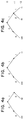
- codes S1 to S6 are arranged in order of the magnitude of the frequency of their occurrence (these magnitudes can be normalized to obtain the probabilities of occurrence).
- the probabilities of occurrence of codes S1 to S6 are respectively 0.35, 0.20, 0.15, 0.15, 0.10 and 0.05 as shown in FIG. 9a. They are therefore arranged in order of codes S1 to S6.
- their composite probability the sum of the two probabilities of occurrence
- codes S6 and S5 have the smallest probability of occurrence, and their composite probability is 0.15.
- this group and the other codes are arranged in order of magnitude of their probabilities of occurrence for composite probability.
- the two codes (or groups) having the smallest probability of occurrence (or composite probability) are taken as a new group, and the composite probability of this group is found. Subsequently, this process is repeated until a listing with the composite probability of one has been effected as shown in FIG. 9a.
- a code tree as shown in Fig. 9b is compiled. "0" and “1” are then allocated in accordance with the branching of this code tree.
- the upper branches are allocated "0", while the lower branches are allocated "1".
- the Huffman codes are obtained by following this branching. For example, as shown by the thick line in FIG. 9b, the fixed length code S4 passes along a branch "0", along a branch "1", and finally along a branch "0", so it is converted to the Huffman code "010".
- the Huffman codes of the codes S1 to S6 found in this way are shown in Table one below. TABLE 1 CODE Huffman Code Code Huffman Code S1 00 S4 010 S2 10 S5 0110 S3 11 S6 0011
- codes which have higher probability of occurrence are converted into Huffman codes of short bit length, while codes which have a lower probability of occurrence are converted into Huffman codes of longer bit length. In this way, the overall bit rate for transmitting a given number of data values can be reduced.
- variable length code In general, to decode such variable length code into fixed length code, a conversion table, embedded in a solid state memory such as a ROM, is used.
- a conversion table embedded in a solid state memory such as a ROM.
- the maximum bit number of the variable length code was taken as being four bits, in an actual image data signal, the maximum bit number may be larger, for example, 17 bits.
- the Huffman coding for the m most significant bits of an n-bit variable length code are necessarily different from the k least significant bits (where n, m and k are natural numbers and m, k ⁇ n) are necessarily different from the patterns of variable length code of n bits or less.
- the patterns "00", "10" of the Huffman code of S1 and S2 are not present in the most significant two bits of the Huffman code of S3, S4, S5 and S6. Consequently, by examining the most significant bits or the least significant bits of the variable length code, it is possible to decode the variable length code.
- a n-bit parallel data signal is coupled to a look-up table (LUT) 111.
- the n-bit signal contains a variable length code word which is used as an address for data stored in LUT 111.
- the variable length code may be n bits in length.
- the data stored in LUT 111 corresponds to the code length and the code value.
- the code length data specifies the length of the variable length code word that has been identified in the n-bit signal.
- the code value is the decoded (i.e. fixed length) value of the variable length code.
- the output of LUT 111 is code length and code value which are z-bit and v-bit parallel data streams respectively.
- variable length code received in the n-bit signal is used as an address to a memory location in LUT 111. After the memory location has been identified, the LUT outputs code length and code value which are stored at the memory location.
- the prior art device of Fig. 11 requires a large memory because an n-bit address must be provided as an input to LUT 111.
- each memory location in LUT 111 stores an z-bit code length and a v bit code value.
- a total of z + v bits are needed to store code length and the code value.
- the total number of bits required for LUT one is 2 n * (z + v) .
- VLC Variable length Code
- variable length code value is 9 bits or more
- a length code "0" is generated by the conversion table 822.
- the conversion table 822 also generates the 5-bit conversion code stored at the address corresponding to the most significant 8 bits.
- a 12-bit code word is supplied to the address input port of conversion table 823.
- the address conversion table 823 is thus designated and the 9-bit fixed length code corresponding to the VLC of 9-bits or more is applied to the second input terminal 830 of selector 824.
- conversion table 822 first attempts to decode the VLC. However, if conversion table 822 fails to decode the VLC, conversion table 822 must first provide additional bits to conversion table 823 prior to decoding by conversion table 823.
- the present invention relates to an apparatus that reduces the memory size of the table used to decode the VLC without slowing the decoding process.
- the present invention further relates to reducing the memory size by reducing the number of bits stored at an address in the LUT.
- the present invention is embodied in a variable length decoder for decoding a variable length code value.
- the variable length decoder includes a code length look-up table which receives n-j bits of an n-bit fixed-length word. A segment of the variable length code value is held in the n-j bits where n and j are integers and j is less than or equal to n.
- the code length look-up table also produces a decoded code length value.
- the variable length decoder also includes a code value look-up table which receives the n-bit fixed-length word and produces a decoded code value of the variable length code.
- FIG. 1 is a block diagram of a variable length decoder according to the first exemplary embodiment of the present invention.
- FIG. 2 is a block diagram of a variable length decoder according to the second exemplary embodiment of the present invention.
- FIGs. 3a-3c are tree diagrams showing a example of how code trees are combined.
- FIGs. 4a-4c are tree diagrams showing another example of how code trees are combined.
- FIGs. 5a-5c are tree diagrams showing another example of how code trees are combined.
- FIG. 6 is a tree diagram showing a partial code tree suitable for use in the coding standard defined by the Moving Picture Expert's Group (MPEG) of the International Standards Organization (ISO) .
- MPEG Moving Picture Expert's Group
- ISO International Standards Organization
- FIGs. 7a-7g are tree diagrams showing the code tree of FIG. 6 divided into lower level code trees to produce smaller conversion tables.
- FIG. 8 is a block diagram of a variable length decoder for decoding MPEG variable length codes according to the third exemplary embodiment of the present invention.
- FIGs. 9a and 9b are tree diagrams explaining huffman codes, where FIG. 9a shows the process of generating Huffman codes, and FIG. 9b, shows a Huffman code tree.
- FIG. 10 (prior art) is a block diagram of a conventional variable length code demodulating apparatus.
- FIG. 11 is a block diagram of a prior art variable length decoder for decoding variable length codes.
- the first exemplary embodiment is described with reference to Fig. 1. According to the first exemplary embodiment, a separate code length table is used to determine the code length of the variable length code.
- an n-bit input stream is provided to code value LUT 3.
- Code value LUT provides a decoded value of the variable length code contained in the n-bit input stream.
- n minus j (n - j) bits of the n-bit input stream are provided to code length LUT 2.
- the separate code length LUT is used to determine the code length of a variable length code contained in the n-bit input stream.
- a segment, the (n-j) most significant bits, of the n-bit input stream is provided to code length LUT 2.
- the entire n-bit input stream is provided to code value LUT 3 to recover the data values of the variable length code from the bit stream.
- the code value LUT 3 does not store the code length of the variable length code.
- code value LUT does not have to include both the code value and its corresponding code length.
- the number of bits stored in the code value LUT at an address may be reduced.
- the code length LUT 2 uses the n-j most significant bits of the n-bit stream as an address in memory. The bits located at that address specify the length of the code. A corresponding address for each variable length code does not have to be provided because some of the variable length codes have the same length. For example, of the codes shown in Table one, the code length can be uniquely determined from the first three bits of the variable length codes even though the longest code word is four bits. Accordingly, j would be one.
- the code length LUT After receiving the n-j bits, the code length LUT provides the code length specifying the length of the variable length code. For example, of the codes shown in Table one, the code length value stored in the memory of the code length LUT would be two for S1 to S3, three for S4 and four for S5 to S6. If j is set equal to one, then the lengths of the variable length codes in Table One may be determined using the three most significant bits of the variable length code. Accordingly, if the three most significant bits of the variable length code is 010, the code length LUT would provide a length value of three. If the three most significant bits of the variable length code is 011, the code length LUT would provide a code length value of four.
- Code value LUT 3 uses the n-bit steam as an address in memory. Stored at the address in memory is a code value for the variable length code. However, the length of the variable length code may not be stored in the memory of code value LUT 3 because it is stored in the memory of code length LUT 2. As a result of using both code length LUT 2 and code value LUT 3 to decode code length and the code value respectively, it is possible to reduce the required memory used for look up tables.
- the memory size for the exemplary embodiment shown in Fig. 1 is the memory size, 2 (n-j) * z , of the code length LUT + the memory size, 2 n * v, of the code value LUT or (2 (n-j) * z) + (2 n * v) .
- the reduction in memory size is calculated as (2 n * (z + v)) - ((2 (n-j) * z) + (2 n * v)) which is equal to (2 n - 2 (n-j) ) * z .
- the size of the memory needed to hold the code length values is reduced by a factor of 2 j .
- FIG. 2 shows a variable length decoder according to a second exemplary embodiment of the invention.
- the decoder receives a segment of a variable length encoded data stream of, for example, n bits.
- the addresses in LUT zero 20 and LUT one 30 are specified by the bits that are applied at the address input terminal, and the data output values of LUT zero 20 and LUT one 30 are specified by the data stored at the designated address.
- the output signal of LUT zero 20 is applied to a first data input port of both multiplexer 40 and multiplexer 41.
- a decode signal is also provided by LUT zero 20 to a control input terminal of multiplexer 40 and 41.
- the output signal of LUT one 30 is applied to a second data input port of multiplexer 40 and multiplexer 41.
- the m MSBs and k LSBs are provided to LUT zero 20 and LUT one 30 respectively.
- Each table decodes the bits provided using the bits as an address within the table and by providing, as its output value, the data stored at that addressed location within the table.
- LUT zero 20 and LUT one 30 decode the m MSBs and the k LSBs respectively of the n-bit fixed length segment, at substantially the same time, thus, performing a parallel decoding operation.
- the data stored at the address location includes a code length indicating the length of the variable length code and a code value which is the decoded value of the variable length code.
- the code length and the code value are z and v bit parallel streams.
- LUT zero 20 In addition to providing the data value at the address indicated by the m MSBs, LUT zero 20 also provides a decode signal, DS, to multiplexers 40 and 41 indicating whether table zero 20 has correctly decoded the variable length code word. If the decode signal is "0", then multiplexers 40 and 41 passes the data provided by LUT zero 20. This is done because LUT zero 20 has successfully decoded the variable length code word and thus, it is unnecessary to consider the output of LUT one 30.
- DS decode signal
- LUT zero 20 has not successfully decoded the variable length code word.
- LUT one 30 has necessarily decoded the variable length code word because LUT zero 20 has not. Accordingly, multiplexers 40 and 41 pass the data value provided to it by LUT one 30.
- variable length decoder is able to reduce the size of the tables needed for conversion while also maintaining decoding speed by using the LUTS in parallel to decode the MSBs and LSBs of the variable length code.
- LUT zero 20 and LUT one 30 have m and k corresponding addresses for the m MSBs and k LSBs of the variable length code respectively.
- the partitioning of the code tables and the number of most significant bits and least significant bits, m and k, are determined in accordance with a method described below. What is desired is to produce a combination of addresses for LUT zero 20 and LUT one 30 such that the combined table is reduced in size in order to minimize the amount of memory required for the tables.
- the method uses code trees which correspond to the variable length codes.
- Table One has variable length codes which may be generated by tracing the branches of the tree shown in Fig. 9b.
- the variable length code for S5 is generated by tracing the branches from A to S5.
- the variable length code produced is 0110.
- n is also the maximum length of the variable length code. If it is assumed that LUT zero 20 has m bits, as noted above, the minimum size k of table one 30 can be determined as follows.
- a level for the main tree is calculated as n minus k (n - k).
- level two is the tree level corresponding to leaf nodes 00 and 10.
- a higher level for example level one, is the tree level corresponding to branch nodes zero and one.
- a tree level may have subtrees below the level.
- level two of FIG. 5a has one subtree.
- the subtree is below branch node 00 with two branches having two leaf nodes 000 and 001.
- a corresponding LUT may be generated.
- the LUT for a respective tree or subtree uses the variable length codes at the leaf nodes of the respective tree or subtree as addresses in memory.
- variable length code can be decoded by LUT one having k LSBs and LUT zero having m MSBs by combining subtrees of the main tree which correspond to the tables respectively. If the subtrees can be combined without overlap, then LUT one having k LSBs and LUT zero having m MSBs will decode the variable length code.
- the tree in FIG. 3c is produced. This is accomplished by combining the different subtrees and the subtrees' corresponding leaf nodes of the main tree shown in FIGs. 3a and 3b.
- the combination of the two subtrees may be performed by laying one tree on top of the other tree.
- leaf nodes of FIG. 3a at level two do not overlap with the leaf nodes of FIG. 3b, then the combination of the subtrees is valid. As a result, k, where k has been set equal to n-m, would be minimized. If, however, as shown in Figs. 4a, 4b, and 4c, subtrees are combined, and an overlap at leaf node 00 occurs, then leaf node 00 is not unique to either of the subtrees shown in FIG. 4a and 4b, and the split shown in FIGs 4a and 4b may not be used.
- FIG. 5a contains an additional leaves at level three.
- FIG. 5a contains an additional leaves at level three.
- Multiple trees may be combined by first combining two subtrees to produce a new tree and then by combining the next subtree with the new tree. This, process may be repeated if additional trees are provided.
- n - k' The method for combining subtrees at the next level, n - k', is same as the method used to combine the subtrees at the n-k level.
- the first value of k which produces a valid split is the lowest value of k which will produce a combined table which uses a smaller amount of memory than a single table that processes n bits in parallel.
- a LUT may be split into a smaller primary and secondary LUTs where each of the smaller tables corresponds to a subtree which may be combined with the other subtrees to produce a tree that corresponds to the original LUT.
- the minimum table size for the secondary tables may be determined. Further, to maximize the overall size of the primary table and the secondary table, the minimum of 2 m +2 k , where m is the bit length for the primary table and k is the bit length for the secondary table, is calculated. The minimum value may be determined by calculating different values of k for different values of m.
- FIGs 7a-7g show examples of different combinations of m and k for LUT zero 20 and LUT one 30 assuming that the maximum length of the variable length code is only 10 bits.
- FIG. 7a shows the case where m for LUT 20 is one bit and k for LUT one 30 is 9 bits.
- FIG. 7b shows the case where m is two bits and k is 8 bits. This combinations is also improper because leaves 01 and 00 conflict.
- FIG. 7c shows the case where m is two bits and k is 9 bits. As shown, a conflict does not exist when the trees corresponding to the tables are combined. Therefore, a valid split of the table has been performed.
- FIGs. 7d-7g This process is repeated in FIGs. 7d-7g for different combinations of m and k bits.
- the splits shown in Fig. 7d, 7e, and 7f can not be combined. However, the split shown in FIG. 7g may be successively combined.
- Table two lists combinations of m and k bits for tables that produce valid combinations.
- the first column represents the number of m bits for LUT zero 20 and the second column shows a corresponding number of k bits for LUT one 30.
- the third column shows the combined table size using different combinations of m and k in column one and two of table two.
- TABLE 2 TABLE ZERO (Bits) TABLE ONE (Bits)
- MEMORY SIZE in words) 1 10 1026 2 9 516 3 9 520 4 8 272 5 8 288 6 8 320 7 8 384 8 3 264 9 3 520 10 0 1024
- the codes defined in the tree for level three and below are in one table, the secondary table, and the codes for the first eight levels of the trees are in another table, the primary table.
- Tables three and four below show the split of a 17 bit segment of the bit stream of LUT zero 20 and LUT one 30 for providing the most significant bits and the least significant bits to the respective tables for decoding the variable length code word.
- the proposed MPEG standard has two tables, "DCT Coefficient Table Zero” and “DCT Coefficient Table One", corresponding to two sets of discrete cosine transform DCT coefficients.
- Table three shows the split for "DCT Coefficient Table Zero"
- Table four shows the split for "DCT Coefficient Table One".
- variable length code may be decoded using parallel LUTs which results in reduced memory usage and high speed decoding.
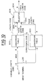
- the third exemplary embodiment is an MPEG decoder which is described with reference to FIG. 8. According to the third exemplary embodiment, a separate code length table is used to determine the code length of the variable length code and to decode the variable length code.
- shifter 610 is connected to a 32 bit input stream.
- the output of shifter 610 is coupled to code length table 620 through a n-j parallel bit stream and to variable length code word table 630 through an n parallel bit stream.
- Shifter 610 is also coupled to control circuitry 660 which is in turn coupled to code length table 620.
- Code length table may also be divided into two tables as indicated by the dashed lines for CDL 621 and multiplexer 622.
- the code length table may be divided into two tables using the LUT dividing method described in the second exemplary embodiment.
- Variable length table 230 includes two LUTs 635, 636 coupled to multiplexer 640. LUTs 635, 636 receive m and k parallel bit streams from shifter 610 respectively. The values n, n-j, m and k may be set equal to 17, 11, 9 and 11 respectively.
- shifter 610 receives a 64-bit parallel segment of the bit stream.
- the 64 bit segment received by shifter 610 includes several variable length code values.
- a programmable segment of the bit stream is provided by the shifter 610 to variable length code word table 630 and to code length (CDL) table 620.
- An n-bit parallel segment of the bit stream is provided to variable length code word table 630 to recover the code values from the variable length code from the bit stream.
- An (n-j)-bit wide parallel bit stream is applied to code length table 620 to acquire the code length.
- the code length is used to separate the variable length encoded value from the subsequent variable length encoded values in the continuous bit stream. Accordingly, the variable length encoded value does not need to be immediately decoded because the subsequent variable encoded value may be identified in the bit stream using the acquired code length.
- code length table 620 Once code length table 620 has decoded the code length, the decoded code length is provided to control circuitry 660.
- the code length table uses the (n-j) bits as an address in memory. The data contained at the address in memory is supplied by the code length table 620 to control circuitry 660.
- Control circuitry 660 uses the code length value to determine the number of bits in the variable length code value at the start of the segment of the data stream being provided by shifter 610. Accordingly, control circuitry 660 controls shifter 610 in response to the code length to provide a subsequent segment of the bit stream immediately after the variable length code value that has been provided.
- the code control circuitry 660 causes shifter 610 to provide a subsequent segment which starts immediately after the two-bit variable length code as the next output value of shifter 610.
- control circuitry 660 can identify the start of the next series of bits regardless of whether the variable length table 630 has decoded the code value.
- CDL 620 may be divided into two CDLs 620, 621 which provide output code lengths to multiplexer 625 for a corresponding LUT 636 and 635.
- variable length table 630 is divided into LUTs 635, 636.
- a separate CDL 621, 620 is created for each of the LUTs 636, 635.
- each CDL 620 and 621 receives a parallel bit segment of the n-bit data stream corresponding to the m and k parallel bit streams received by LUTs 636 and 635 respectively. Then each CDL 621, 620 decodes its respective segment.
- CDL 621 provides a detected code length signal, DCL, of "1" to multiplexer 625 if CDL 621 has obtained a valid code length.
- CDL 621 provides a DCL of "0" to multiplexer 625 if CDL 621 has not obtained a valid code length. If multiplexer 625 receives a DCL "1”, multiplexer 625 provides the code length provided by CDL 621 to control circuitry 660. However, if multiplexer 625 receives a DCL "0”, multiplexer 625 provides the code length provided by CDL 620 to control circuitry 660.
- Variable length table 620 uses the method described in the second exemplary embodiment to decode the variable length code. As a result of using both code length table 620 and variable length table 630 to decode code length and the variable length code word respectively, it is possible to operate the decoding system at a high rate of speed while also reducing the required memory used for look up tables to decode encoded values. Further, the decoding apparatus may be prepared to receive the next segment of bits and process those bits without waiting for all of the previous data in the previous segment of bits to be decoded.
- the first exemplary embodiment may be modified so that LUT zero 20 supplies the code length value of the variable length code to shifter 10 through parallel bit line 21.
- LUT zero 20 would also store the code length value in addition to the decoded variable length code value at an address corresponding to the m MSBs. Accordingly, LUT zero 20 supplies both the code length value to shifter 10 and a decoded variable length code value to multiplexer 40.
- a primary LUT into more than two LUTs to minimize the required size for the LUTs. This process is accomplished by first dividing a primary LUT into two LUTs having m-bit and k-bit input data streams using the method described in the second exemplary embodiment. Then the LUT having the k-bit input data stream is divided as if it is a primary LUT using the method described in the second exemplary embodiment.
Landscapes
- Engineering & Computer Science (AREA)
- Theoretical Computer Science (AREA)
- Compression, Expansion, Code Conversion, And Decoders (AREA)
- Compression Or Coding Systems Of Tv Signals (AREA)
- Compression Of Band Width Or Redundancy In Fax (AREA)
Applications Claiming Priority (2)
| Application Number | Priority Date | Filing Date | Title |
|---|---|---|---|
| US08/238,362 US5550542A (en) | 1994-05-04 | 1994-05-04 | Variable length code look-up table having separate code length determination |
| US238362 | 1994-05-04 |
Publications (2)
| Publication Number | Publication Date |
|---|---|
| EP0683568A1 true EP0683568A1 (de) | 1995-11-22 |
| EP0683568B1 EP0683568B1 (de) | 2002-08-28 |
Family
ID=22897540
Family Applications (1)
| Application Number | Title | Priority Date | Filing Date |
|---|---|---|---|
| EP95106478A Expired - Lifetime EP0683568B1 (de) | 1994-05-04 | 1995-04-28 | Decodierung eines Huffman Codes mit MSB und LSB Tabellen |
Country Status (4)
| Country | Link |
|---|---|
| US (1) | US5550542A (de) |
| EP (1) | EP0683568B1 (de) |
| JP (1) | JP3341962B2 (de) |
| DE (1) | DE69527883T2 (de) |
Cited By (2)
| Publication number | Priority date | Publication date | Assignee | Title |
|---|---|---|---|---|
| GB2313511A (en) * | 1996-05-25 | 1997-11-26 | Motorola Inc | Decoding variable length codewords such as MPEG2 DCT coefficients |
| EP0814614A2 (de) * | 1996-06-19 | 1997-12-29 | Hewlett-Packard Company | Hochbitrate Huffman Dekodierer |
Families Citing this family (21)
| Publication number | Priority date | Publication date | Assignee | Title |
|---|---|---|---|---|
| KR960020018A (ko) * | 1994-11-17 | 1996-06-17 | 배순훈 | 가변길이복호화장치 |
| JP2687926B2 (ja) * | 1995-05-24 | 1997-12-08 | 日本電気株式会社 | 符号復号化装置 |
| US5694127A (en) * | 1995-10-17 | 1997-12-02 | Zapex Technologies, Inc. | Method and apparatus for efficiently generating variable length code data |
| US5835145A (en) * | 1996-01-19 | 1998-11-10 | Lsi Logic Corporation | Conversion system using programmable tables for compressing transform coefficients |
| US5745504A (en) * | 1996-06-25 | 1998-04-28 | Telefonaktiebolaget Lm Ericsson | Bit error resilient variable length code |
| US6011498A (en) * | 1996-12-20 | 2000-01-04 | Philips Electronics North America Corporation | Dual-speed variable length decoding architecture for MPEG-2 video data |
| US6351570B1 (en) | 1997-04-01 | 2002-02-26 | Matsushita Electric Industrial Co., Ltd. | Image coding and decoding apparatus, method of image coding and decoding, and recording medium for recording program for image coding and decoding |
| US6044460A (en) * | 1998-01-16 | 2000-03-28 | Lsi Logic Corporation | System and method for PC-relative address generation in a microprocessor with a pipeline architecture |
| US6850647B1 (en) * | 1999-07-30 | 2005-02-01 | Michael L. Gough | System, method and article of manufacture for decompressing digital camera sensor data |
| US6633969B1 (en) | 2000-08-11 | 2003-10-14 | Lsi Logic Corporation | Instruction translation system and method achieving single-cycle translation of variable-length MIPS16 instructions |
| US7123774B2 (en) * | 2002-11-27 | 2006-10-17 | General Electric Company | System and method for coding data |
| US7093099B2 (en) * | 2002-12-12 | 2006-08-15 | Alacritech, Inc. | Native lookup instruction for file-access processor searching a three-level lookup cache for variable-length keys |
| US7358870B2 (en) * | 2003-09-02 | 2008-04-15 | Nokia Corporation | Huffman coding and decoding based upon sectioning of a Huffman coding tree |
| US6839005B1 (en) * | 2003-11-07 | 2005-01-04 | Broadcom Corporation | Low memory and MIPS efficient technique for decoding Huffman codes using multi-stage, multi-bits lookup at different levels |
| US7360142B1 (en) * | 2004-03-03 | 2008-04-15 | Marvell Semiconductor Israel Ltd. | Methods, architectures, circuits, software and systems for CRC determination |
| US7434150B1 (en) | 2004-03-03 | 2008-10-07 | Marvell Israel (M.I.S.L.) Ltd. | Methods, circuits, architectures, software and systems for determining a data transmission error and/or checking or confirming such error determinations |
| US7271748B2 (en) * | 2004-09-13 | 2007-09-18 | Texas Instruments Incorporated | System and method for providing a thermometer coded output filter |
| JP4841496B2 (ja) * | 2007-04-26 | 2011-12-21 | パナソニック株式会社 | 可変長符号復号化装置 |
| JP4763853B2 (ja) * | 2008-03-31 | 2011-08-31 | パナソニック株式会社 | 可変長符号復号化装置及びその方法 |
| DE102010009263B4 (de) * | 2010-02-25 | 2012-04-12 | Knorr-Bremse Systeme für Nutzfahrzeuge GmbH | Verfahren zur Datenübertragung zu einem elektronischen Steuergerät |
| US9787323B1 (en) * | 2016-12-11 | 2017-10-10 | Microsoft Technology Licensing, Llc | Huffman tree decompression |
Citations (3)
| Publication number | Priority date | Publication date | Assignee | Title |
|---|---|---|---|---|
| US5138316A (en) * | 1989-10-30 | 1992-08-11 | Kabushiki Kaisha Toshiba | Variable length code demodulating apparatus and address control method thereof |
| WO1993013603A1 (en) * | 1991-12-23 | 1993-07-08 | Intel Corporation | Circuitry for decoding huffman codes |
| US5253053A (en) * | 1990-12-31 | 1993-10-12 | Apple Computer, Inc. | Variable length decoding using lookup tables |
Family Cites Families (10)
| Publication number | Priority date | Publication date | Assignee | Title |
|---|---|---|---|---|
| US4044347A (en) * | 1975-05-19 | 1977-08-23 | International Business Machines Corporation | Variable-length to fixed-length conversion of minimum-redundancy codes |
| JPS5564445A (en) * | 1978-11-08 | 1980-05-15 | Nec Corp | Code converter circuit |
| JPH03143028A (ja) * | 1989-10-27 | 1991-06-18 | Yamaha Corp | 可変長符号の復号回路 |
| US5173695A (en) * | 1990-06-29 | 1992-12-22 | Bell Communications Research, Inc. | High-speed flexible variable-length-code decoder |
| US5181031A (en) * | 1991-07-30 | 1993-01-19 | Lsi Logic Corporation | Method and apparatus for decoding huffman codes by detecting a special class |
| US5422641A (en) * | 1991-12-09 | 1995-06-06 | Matsushita Electric Industrial Co., Ltd. | Digital modulator and demodulator circuit |
| JPH05327517A (ja) * | 1992-05-21 | 1993-12-10 | Mitsubishi Electric Corp | デコード装置 |
| US5325092A (en) * | 1992-07-07 | 1994-06-28 | Ricoh Company, Ltd. | Huffman decoder architecture for high speed operation and reduced memory |
| JP3136796B2 (ja) * | 1992-09-24 | 2001-02-19 | ソニー株式会社 | 可変長符号デコーダ |
| US5343195A (en) * | 1992-12-18 | 1994-08-30 | Thomson Consumer Electronics, Inc. | Variable length codeword decoding apparatus |
-
1994
- 1994-05-04 US US08/238,362 patent/US5550542A/en not_active Expired - Fee Related
-
1995
- 1995-04-28 DE DE69527883T patent/DE69527883T2/de not_active Expired - Fee Related
- 1995-04-28 EP EP95106478A patent/EP0683568B1/de not_active Expired - Lifetime
- 1995-05-02 JP JP10885895A patent/JP3341962B2/ja not_active Expired - Fee Related
Patent Citations (3)
| Publication number | Priority date | Publication date | Assignee | Title |
|---|---|---|---|---|
| US5138316A (en) * | 1989-10-30 | 1992-08-11 | Kabushiki Kaisha Toshiba | Variable length code demodulating apparatus and address control method thereof |
| US5253053A (en) * | 1990-12-31 | 1993-10-12 | Apple Computer, Inc. | Variable length decoding using lookup tables |
| WO1993013603A1 (en) * | 1991-12-23 | 1993-07-08 | Intel Corporation | Circuitry for decoding huffman codes |
Cited By (5)
| Publication number | Priority date | Publication date | Assignee | Title |
|---|---|---|---|---|
| GB2313511A (en) * | 1996-05-25 | 1997-11-26 | Motorola Inc | Decoding variable length codewords such as MPEG2 DCT coefficients |
| GB2313511B (en) * | 1996-05-25 | 2000-03-22 | Motorola Inc | Decoder circuit and method |
| EP0814614A2 (de) * | 1996-06-19 | 1997-12-29 | Hewlett-Packard Company | Hochbitrate Huffman Dekodierer |
| EP0814614A3 (de) * | 1996-06-19 | 2000-01-05 | Hewlett-Packard Company | Hochbitrate Huffman Dekodierer |
| SG73441A1 (en) * | 1996-06-19 | 2003-11-27 | Hewlett Packard Co | High bit-rate huffman decoding |
Also Published As
| Publication number | Publication date |
|---|---|
| EP0683568B1 (de) | 2002-08-28 |
| JPH07307675A (ja) | 1995-11-21 |
| JP3341962B2 (ja) | 2002-11-05 |
| US5550542A (en) | 1996-08-27 |
| DE69527883T2 (de) | 2003-04-30 |
| DE69527883D1 (de) | 2002-10-02 |
Similar Documents
| Publication | Publication Date | Title |
|---|---|---|
| US5550542A (en) | Variable length code look-up table having separate code length determination | |
| US5541595A (en) | Variable length code decoder for simultaneous decoding the most significant bits and the least significant bits of a variable length code | |
| US6219457B1 (en) | Method and system for decoding data encoded in a variable length code word | |
| EP0426429B1 (de) | Vorrichtung zur Dekodierung von Kode variabler Länge und geeignetes Adresssteuerungsverfahren | |
| US5325092A (en) | Huffman decoder architecture for high speed operation and reduced memory | |
| US5208593A (en) | Method and structure for decoding Huffman codes using leading ones detection | |
| US5227789A (en) | Modified huffman encode/decode system with simplified decoding for imaging systems | |
| US7817864B2 (en) | Coding apparatus and decoding apparatus | |
| EP0589682A2 (de) | Dekodierer für veränderliche Längenkodes | |
| US5254991A (en) | Method and apparatus for decoding Huffman codes | |
| JPH0818460A (ja) | ハフマンデコーダー | |
| EP2922208A1 (de) | System und Verfahren für die kontextabhängige, adaptive, arithmetische Binärkodierung und -dekodierung | |
| US6954555B2 (en) | Variable length coding unit and variable length decoding unit | |
| JPH0746142A (ja) | データ圧縮方式 | |
| CN1155221C (zh) | 编码方法及系统以及译码方法及系统 | |
| US5594435A (en) | Permutation-based data compression | |
| US6546053B1 (en) | System and method for decoding signal and method of generating lookup table for using in signal decoding process | |
| JP4098187B2 (ja) | 可変長コード復号化装置及び方法 | |
| JPH1065549A (ja) | 可変長符号化データ値の長さを決定する装置、可変長符号化データ値のデータストリームを復号化する装置および可変長符号化データ値の長さを決定する方法 | |
| US5907635A (en) | Picture data decompression apparatus | |
| US6529551B1 (en) | Data efficient quantization table for a digital video signal processor | |
| US5825312A (en) | DX JPEG Huffman decoder | |
| US5835033A (en) | Decoding apparatus and method for coded data | |
| JPH10271016A (ja) | 符号/復号化器 | |
| US5754128A (en) | Variable-length code encoding and segmenting apparatus having a byte alignment unit |
Legal Events
| Date | Code | Title | Description |
|---|---|---|---|
| PUAI | Public reference made under article 153(3) epc to a published international application that has entered the european phase |
Free format text: ORIGINAL CODE: 0009012 |
|
| AK | Designated contracting states |
Kind code of ref document: A1 Designated state(s): DE FR GB |
|
| 17P | Request for examination filed |
Effective date: 19960311 |
|
| 17Q | First examination report despatched |
Effective date: 19990604 |
|
| GRAG | Despatch of communication of intention to grant |
Free format text: ORIGINAL CODE: EPIDOS AGRA |
|
| RTI1 | Title (correction) |
Free format text: DECODING OF HUFFMAN CODES WITH MSB AND LSB LOOK-UP TABLES |
|
| GRAG | Despatch of communication of intention to grant |
Free format text: ORIGINAL CODE: EPIDOS AGRA |
|
| GRAH | Despatch of communication of intention to grant a patent |
Free format text: ORIGINAL CODE: EPIDOS IGRA |
|
| GRAH | Despatch of communication of intention to grant a patent |
Free format text: ORIGINAL CODE: EPIDOS IGRA |
|
| GRAA | (expected) grant |
Free format text: ORIGINAL CODE: 0009210 |
|
| AK | Designated contracting states |
Kind code of ref document: B1 Designated state(s): DE FR GB |
|
| REG | Reference to a national code |
Ref country code: GB Ref legal event code: FG4D |
|
| REF | Corresponds to: |
Ref document number: 69527883 Country of ref document: DE Date of ref document: 20021002 |
|
| ET | Fr: translation filed | ||
| PGFP | Annual fee paid to national office [announced via postgrant information from national office to epo] |
Ref country code: FR Payment date: 20030408 Year of fee payment: 9 |
|
| PGFP | Annual fee paid to national office [announced via postgrant information from national office to epo] |
Ref country code: GB Payment date: 20030423 Year of fee payment: 9 |
|
| PGFP | Annual fee paid to national office [announced via postgrant information from national office to epo] |
Ref country code: DE Payment date: 20030508 Year of fee payment: 9 |
|
| PLBE | No opposition filed within time limit |
Free format text: ORIGINAL CODE: 0009261 |
|
| STAA | Information on the status of an ep patent application or granted ep patent |
Free format text: STATUS: NO OPPOSITION FILED WITHIN TIME LIMIT |
|
| 26N | No opposition filed |
Effective date: 20030530 |
|
| PG25 | Lapsed in a contracting state [announced via postgrant information from national office to epo] |
Ref country code: GB Free format text: LAPSE BECAUSE OF NON-PAYMENT OF DUE FEES Effective date: 20040428 |
|
| PG25 | Lapsed in a contracting state [announced via postgrant information from national office to epo] |
Ref country code: DE Free format text: LAPSE BECAUSE OF NON-PAYMENT OF DUE FEES Effective date: 20041103 |
|
| GBPC | Gb: european patent ceased through non-payment of renewal fee |
Effective date: 20040428 |
|
| PG25 | Lapsed in a contracting state [announced via postgrant information from national office to epo] |
Ref country code: FR Free format text: LAPSE BECAUSE OF NON-PAYMENT OF DUE FEES Effective date: 20041231 |
|
| REG | Reference to a national code |
Ref country code: FR Ref legal event code: ST |