EP0683408A1 - Multiplexer/Demultiplexer aus optischer Faser mit einer Reflexionsschicht um den optischen Koppelbereich - Google Patents
Multiplexer/Demultiplexer aus optischer Faser mit einer Reflexionsschicht um den optischen Koppelbereich Download PDFInfo
- Publication number
- EP0683408A1 EP0683408A1 EP95104701A EP95104701A EP0683408A1 EP 0683408 A1 EP0683408 A1 EP 0683408A1 EP 95104701 A EP95104701 A EP 95104701A EP 95104701 A EP95104701 A EP 95104701A EP 0683408 A1 EP0683408 A1 EP 0683408A1
- Authority
- EP
- European Patent Office
- Prior art keywords
- optical
- optical fiber
- demultiplexer
- reflection coefficient
- high reflection
- Prior art date
- Legal status (The legal status is an assumption and is not a legal conclusion. Google has not performed a legal analysis and makes no representation as to the accuracy of the status listed.)
- Withdrawn
Links
Images
Classifications
-
- G—PHYSICS
- G02—OPTICS
- G02B—OPTICAL ELEMENTS, SYSTEMS OR APPARATUS
- G02B6/00—Light guides; Structural details of arrangements comprising light guides and other optical elements, e.g. couplings
- G02B6/24—Coupling light guides
- G02B6/26—Optical coupling means
- G02B6/28—Optical coupling means having data bus means, i.e. plural waveguides interconnected and providing an inherently bidirectional system by mixing and splitting signals
- G02B6/2804—Optical coupling means having data bus means, i.e. plural waveguides interconnected and providing an inherently bidirectional system by mixing and splitting signals forming multipart couplers without wavelength selective elements, e.g. "T" couplers, star couplers
- G02B6/2821—Optical coupling means having data bus means, i.e. plural waveguides interconnected and providing an inherently bidirectional system by mixing and splitting signals forming multipart couplers without wavelength selective elements, e.g. "T" couplers, star couplers using lateral coupling between contiguous fibres to split or combine optical signals
- G02B6/2835—Optical coupling means having data bus means, i.e. plural waveguides interconnected and providing an inherently bidirectional system by mixing and splitting signals forming multipart couplers without wavelength selective elements, e.g. "T" couplers, star couplers using lateral coupling between contiguous fibres to split or combine optical signals formed or shaped by thermal treatment, e.g. couplers
Definitions
- the present invention relates to an optical multiplexer/demultiplexer which demultiplexes light propagating in an optical fiber circuit into two or more optical fiber circuits or multiplexes light propagating in a multiple of optical fiber circuits into an optical fiber circuit and, more particular to an optical fiber multiplexer/demultiplexer of optical fiber having a reflection layers with high reflection coefficient formed of an out side of a coupling portion where light power loss due to the leakage of light through the outer surfaces of the optical fiber clads into free space greatly be reduced by the reflection layer with high reflection coefficient.
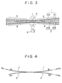
- Figure 3 shows a conventional making processes of an optical fiber multiplexer/demultiplexer by drawing and partly fusing optical fibers.
- the optical multiplexer/demultiplexer of optical fiber which is shown in Figure 3, consists of a 1x2 matrix circuit which is fabricated by such processes that clads 101, 102 of optical bare fibers 1, 2 are partly fused by heater, i.e., burner 3 while they are partly arranged in parallel along the axis of the multiplexer/demultiplexer. Stripped optical fibers 1, 2 are drawn along the axis thereof at low speed while they are heated and fused. Thereafter, each pair of tapered portions whose midpoint 4 has the minimum radius are formed from each of the optical fibers 1, 2 so that the pair of tapered portions are drawn and fused each other.
- a 1x2 optical multiplexer/demultiplexer which has been fabricated by the above processes is inserted into a glass tube (not shown), and held therein with adhesive.
- Cores 101, 201 within which light can propagate, and clads 102, 202 which keep light within cores 101, 201 are respectively concentrically arranged. As the radius of an optical fiber is gradually reduced by fusing and drawing the optical fiber, mode radius ⁇ of each of optical fiber cores 101, 201 is extended.
- mode radius ⁇ is given by the following equation when radius a of the optical fiber core changes.
- ⁇ a(0.65+1.619/V 1.5 +2.879/V6)
- ⁇ ( ⁇ m) is the wavelength of the light emitted from a light source
- a( ⁇ m) is the radius of the optical fiber core
- n1 is the refractive index of the optical fiber core
- n2 is the refractive index of the optical fiber clad.
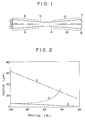
- Figure 2 shows the relationships of mode radius ( ⁇ ), radius (a) of an optical fiber core, and radius (b) of the optical fiber clad as functions of the ratio (D min /D n ) of the minimum radius of the core and clad of the tapered portions to those of the normal optical fiber.
- radius b of the optical fiber clad and mode radius ⁇ are respectively 27 to 28 ⁇ m, which are the same.
- FIG. 4 shows a schematic diagram of an optical fiber 1x2 optical multiplexer/demultiplexer.
- optical fibers 1, 2 Since the extended mode radii ( ⁇ ) of optical fibers 1, 2 are overlapped each other in a pair of tapered portions 5, 6, light Pa propagating in a branch 1a of an optical fiber 1 is split into optical fibers 1b, 2b. Due to the overlapping, the optical fiber 1 is optically coupled to the optical fiber 2.
- Light Pa appears at a port 1b as light Pb and at a port 2b as light Pc.
- Light Pa is greater than light Pb+Pc due to light loss in a pair of the tapered portions 5, 6.
- the loss of the optical multiplexer/demultiplexer sold in the market is 0.2 to 0.5 dB.
- the optical multiplexer/demultiplexer having an loss of greater than 0.5dB is thrown away as a defective one.
- An object of the present invention is to provide an extreamly low loss optical multiplexer/demultiplexer which splits light propagating in an optical fiber into two or more optical fibers, or combines light propagating in a plurality of optical fibers to an optical fiber.
- Another object of the present invention is to provide an multiplexer/demultiplexer of optical fiber having a reflection layer with high reflection coefficient in its optical coupling portion which can greatly reduce the optical coupling loss.
- the optical fiber multiplexer/demultiplexer of the present invention has the reflection layer with high reflection coefficient in the coupling portion thereof.
- the reflection layer consists of a film layer with high reflection coefficient on the outer surface of a pair of tapered portions formed by fusing and drawing two or more optical fibers which are arranged in parallel and contacted each other so that the radii of the core and clad are minimized at the midpoint of the fused tapered portions while the clads are fused.
- the film layer with high reflection coefficient is made of a mirror coating layer of dielectric materials, or a metal film layer with high reflection coefficient, i.e., aluminum, gold, or silver film.
- Figure 1 shows an embodiment of an optical multiplexer/demultiplexer of optical fiber of the present invention having a reflection layer with high reflection coefficient in the optical coupling portion thereof.
- Figure 2 shows the relationships of mode radius ( ⁇ ), radius (a) of the optical fiber core, and radius (b) of the optical fiber clad as function of the ratio of the minimum radius of the tapered portions to the radius of the normal optical fiber.
- Figure 3 shows a process of making of a conventional optical fiber optical multiplexer/demultiplexer.
- Figure 4 shows a schematic diagram of a 1x2 optical multiplexer/demultiplexer of optical fiber.
- optical multiplexer/demultiplexer of optical fiber having the reflection layer with high reflection coefficient in accordance with the present invention, will be described in detail referring to the drawings.
- Figure 1 shows an embodiment of a 1x2 optical multiplexer/demultiplexer of optical fiber of the present invention having a reflection layer with high reflection coefficient in an optical coupling portion thereof.
- Optical fibers 7,8 in Figure 1 are drawn and fused by heat so that each pair of tapered portions 9,10 are formed on both sides of the midpoint where the radii of optical fibers 9, 10 are minimized.
- the fabrication process of the tapered portion and a coupling portion are the same as those which have been described referring to Figure 3. Thereafter, a mirror coating layer of dielectric materials 11 with high reflection coefficient, or metal film layer 11 with high reflection coefficient, i.e., aluminum, copper, gold or silver film is evaporated onto the outer surface of the clads of each pair of tapered portions 9, 10.
- the mirror coating layer of dielectric materials in the optical multiplexer/demultiplexer has a reflection coefficient of 98% or more at an incident angle of 45 degrees or less.
- a metal film layer such as copper, gold, or silver film has a reflection coefficient of 98% or more when light is incident on this metal film layer at right angle.
- the optical fiber optical multiplexer/demultiplexer of the invention having the reflection film with high reflection coefficient in the optical coupling portion thereof, is made by the following processes. Clads of two or more striped optical fibers are fused by heating while the optical fibers are arranged in parallel and contacted each other, the respective pairs of tapered portions are formed by drawing the optical fibers along the axis thereof so that the radii of the cores and clads are minimized in the portion where the clads are contacted each other. Then film layer with high reflection coefficient are formed outside the tapered portions.
- optical multiplexer/demultiplexer of optical fiber having the reflection film with high reflection coefficient outside the optical coupling portion thereof is made by the conventional process as described above.
- the optical multiplexer/demultiplexer of optical fiber of present invention is superior than the conventional device in that light going out of the outer surfaces of the tapered portions can be few compared with that in the conventional device, and thus the loss can greatly be reduced.
- the metal films with high reflection coefficient enhance the mechanical strength of the tapered portions of the optical fibers, which improves the handling capability of the optical fibers, reducing the frequency of failures, and reduce the production cost.
Landscapes
- Physics & Mathematics (AREA)
- General Physics & Mathematics (AREA)
- Optics & Photonics (AREA)
- Optical Couplings Of Light Guides (AREA)
Applications Claiming Priority (2)
| Application Number | Priority Date | Filing Date | Title |
|---|---|---|---|
| JP129921/94 | 1994-05-20 | ||
| JP12992194A JPH07318746A (ja) | 1994-05-20 | 1994-05-20 | 結合部に高反射率の反射被覆をした光ファイバ光分岐合流器 |
Publications (1)
| Publication Number | Publication Date |
|---|---|
| EP0683408A1 true EP0683408A1 (de) | 1995-11-22 |
Family
ID=15021702
Family Applications (1)
| Application Number | Title | Priority Date | Filing Date |
|---|---|---|---|
| EP95104701A Withdrawn EP0683408A1 (de) | 1994-05-20 | 1995-03-30 | Multiplexer/Demultiplexer aus optischer Faser mit einer Reflexionsschicht um den optischen Koppelbereich |
Country Status (2)
| Country | Link |
|---|---|
| EP (1) | EP0683408A1 (de) |
| JP (1) | JPH07318746A (de) |
Cited By (2)
| Publication number | Priority date | Publication date | Assignee | Title |
|---|---|---|---|---|
| WO2003067563A1 (en) * | 2002-02-06 | 2003-08-14 | Screen Technology Limited | Display with optical fibre face plate |
| US7231120B2 (en) | 2002-07-30 | 2007-06-12 | Mbda Uk Limited | Tapered optical fibre with a reflective coating at the tapered end |
Citations (4)
| Publication number | Priority date | Publication date | Assignee | Title |
|---|---|---|---|---|
| US4360248A (en) * | 1979-04-18 | 1982-11-23 | International Telephone And Telegraph Corporation | Multiport optical communication system and optical star structure therefor |
| US4392712A (en) * | 1977-03-23 | 1983-07-12 | Tokyo Shibaura Electric Co., Ltd. | Light distributor |
| EP0447700A1 (de) * | 1990-03-07 | 1991-09-25 | Fujikura Ltd. | Faseroptischer Richtkoppler |
| JPH05127038A (ja) * | 1991-11-06 | 1993-05-25 | Shin Etsu Chem Co Ltd | 保護皮覆を設けた光分岐結合器 |
Family Cites Families (2)
| Publication number | Priority date | Publication date | Assignee | Title |
|---|---|---|---|---|
| JPS60217312A (ja) * | 1984-04-13 | 1985-10-30 | Nippon Telegr & Teleph Corp <Ntt> | 光ケ−ブル伝送路 |
| JPS62266509A (ja) * | 1986-05-15 | 1987-11-19 | Sumitomo Electric Ind Ltd | 光フアイバ結合装置 |
-
1994
- 1994-05-20 JP JP12992194A patent/JPH07318746A/ja active Pending
-
1995
- 1995-03-30 EP EP95104701A patent/EP0683408A1/de not_active Withdrawn
Patent Citations (4)
| Publication number | Priority date | Publication date | Assignee | Title |
|---|---|---|---|---|
| US4392712A (en) * | 1977-03-23 | 1983-07-12 | Tokyo Shibaura Electric Co., Ltd. | Light distributor |
| US4360248A (en) * | 1979-04-18 | 1982-11-23 | International Telephone And Telegraph Corporation | Multiport optical communication system and optical star structure therefor |
| EP0447700A1 (de) * | 1990-03-07 | 1991-09-25 | Fujikura Ltd. | Faseroptischer Richtkoppler |
| JPH05127038A (ja) * | 1991-11-06 | 1993-05-25 | Shin Etsu Chem Co Ltd | 保護皮覆を設けた光分岐結合器 |
Non-Patent Citations (1)
| Title |
|---|
| PATENT ABSTRACTS OF JAPAN vol. 17, no. 495 (P - 1608) 7 September 1993 (1993-09-07) * |
Cited By (2)
| Publication number | Priority date | Publication date | Assignee | Title |
|---|---|---|---|---|
| WO2003067563A1 (en) * | 2002-02-06 | 2003-08-14 | Screen Technology Limited | Display with optical fibre face plate |
| US7231120B2 (en) | 2002-07-30 | 2007-06-12 | Mbda Uk Limited | Tapered optical fibre with a reflective coating at the tapered end |
Also Published As
| Publication number | Publication date |
|---|---|
| JPH07318746A (ja) | 1995-12-08 |
Similar Documents
| Publication | Publication Date | Title |
|---|---|---|
| US4296995A (en) | Optical fiber beam splitter couplers employing coatings with dichroic properties | |
| JP3124465B2 (ja) | 光カプラ | |
| CN1277137C (zh) | 光学互连组件及相应方法 | |
| US4252403A (en) | Coupler for a graded index fiber | |
| JP2996602B2 (ja) | 定偏波光ファイバ用光分岐結合器 | |
| EP0683410B1 (de) | Faseroptische Lichteinkopplungsschnittstelle mit vergrösserter Einfallsfläche | |
| US6173095B1 (en) | Optical fiber and method for coupling optical fibers | |
| US4830453A (en) | Device for optically coupling a radiation source to an optical transmission fiber | |
| JP3888942B2 (ja) | 光ファイバ部品 | |
| EP0683408A1 (de) | Multiplexer/Demultiplexer aus optischer Faser mit einer Reflexionsschicht um den optischen Koppelbereich | |
| EP0139171A2 (de) | Vorrichtung zum Ausrichten optischer Fibern | |
| JP2002182062A (ja) | コネクター型光合分波器 | |
| JP3295053B2 (ja) | 定偏波光ファイバ用4心フェルール | |
| JPH08262229A (ja) | 光ファイバ型無反射終端 | |
| JP3083015B2 (ja) | 導波路型光分岐結合素子 | |
| JP2002189144A (ja) | 2心ファイバコリメータ及び光合分波器 | |
| JP2005173213A (ja) | 光コリメータおよびこれを用いた光部品 | |
| JP2749842B2 (ja) | 合波分波器 | |
| JP2533127B2 (ja) | 光分波器 | |
| JP2931914B2 (ja) | 光ファイバー分岐結合器 | |
| JPH07253520A (ja) | 石英系ガラス導波路型光デバイス及びこれに融着接続されるシングルモード光ファイバ | |
| JP2004212869A (ja) | 光部品、光部品の製造方法 | |
| WO1996004580A1 (en) | Optical attenuator having a partially reflective surface | |
| JPH03131804A (ja) | 光コネクタ用光ファイバ接続端子 | |
| JPH09243852A (ja) | 光ファイバカプラ |
Legal Events
| Date | Code | Title | Description |
|---|---|---|---|
| PUAI | Public reference made under article 153(3) epc to a published international application that has entered the european phase |
Free format text: ORIGINAL CODE: 0009012 |
|
| AK | Designated contracting states |
Kind code of ref document: A1 Designated state(s): DE FR GB |
|
| 17P | Request for examination filed |
Effective date: 19951113 |
|
| 17Q | First examination report despatched |
Effective date: 19980604 |
|
| STAA | Information on the status of an ep patent application or granted ep patent |
Free format text: STATUS: THE APPLICATION IS DEEMED TO BE WITHDRAWN |
|
| 18D | Application deemed to be withdrawn |
Effective date: 19981015 |