EP0683308A2 - System zur Leistungssteuerung oder Leistungsregelung einer aufgeladenen Brennkraftmaschine - Google Patents
System zur Leistungssteuerung oder Leistungsregelung einer aufgeladenen Brennkraftmaschine Download PDFInfo
- Publication number
- EP0683308A2 EP0683308A2 EP95105576A EP95105576A EP0683308A2 EP 0683308 A2 EP0683308 A2 EP 0683308A2 EP 95105576 A EP95105576 A EP 95105576A EP 95105576 A EP95105576 A EP 95105576A EP 0683308 A2 EP0683308 A2 EP 0683308A2
- Authority
- EP
- European Patent Office
- Prior art keywords
- internal combustion
- combustion engine
- operating range
- setpoint
- throttle valve
- Prior art date
- Legal status (The legal status is an assumption and is not a legal conclusion. Google has not performed a legal analysis and makes no representation as to the accuracy of the status listed.)
- Withdrawn
Links
Images

Classifications
-
- B—PERFORMING OPERATIONS; TRANSPORTING
- B60—VEHICLES IN GENERAL
- B60K—ARRANGEMENT OR MOUNTING OF PROPULSION UNITS OR OF TRANSMISSIONS IN VEHICLES; ARRANGEMENT OR MOUNTING OF PLURAL DIVERSE PRIME-MOVERS IN VEHICLES; AUXILIARY DRIVES FOR VEHICLES; INSTRUMENTATION OR DASHBOARDS FOR VEHICLES; ARRANGEMENTS IN CONNECTION WITH COOLING, AIR INTAKE, GAS EXHAUST OR FUEL SUPPLY OF PROPULSION UNITS IN VEHICLES
- B60K28/00—Safety devices for propulsion-unit control, specially adapted for, or arranged in, vehicles, e.g. preventing fuel supply or ignition in the event of potentially dangerous conditions
- B60K28/10—Safety devices for propulsion-unit control, specially adapted for, or arranged in, vehicles, e.g. preventing fuel supply or ignition in the event of potentially dangerous conditions responsive to conditions relating to the vehicle
- B60K28/16—Safety devices for propulsion-unit control, specially adapted for, or arranged in, vehicles, e.g. preventing fuel supply or ignition in the event of potentially dangerous conditions responsive to conditions relating to the vehicle responsive to, or preventing, skidding of wheels
-
- F—MECHANICAL ENGINEERING; LIGHTING; HEATING; WEAPONS; BLASTING
- F02—COMBUSTION ENGINES; HOT-GAS OR COMBUSTION-PRODUCT ENGINE PLANTS
- F02D—CONTROLLING COMBUSTION ENGINES
- F02D11/00—Arrangements for, or adaptations to, non-automatic engine control initiation means, e.g. operator initiated
- F02D11/06—Arrangements for, or adaptations to, non-automatic engine control initiation means, e.g. operator initiated characterised by non-mechanical control linkages, e.g. fluid control linkages or by control linkages with power drive or assistance
- F02D11/10—Arrangements for, or adaptations to, non-automatic engine control initiation means, e.g. operator initiated characterised by non-mechanical control linkages, e.g. fluid control linkages or by control linkages with power drive or assistance of the electric type
-
- F—MECHANICAL ENGINEERING; LIGHTING; HEATING; WEAPONS; BLASTING
- F02—COMBUSTION ENGINES; HOT-GAS OR COMBUSTION-PRODUCT ENGINE PLANTS
- F02D—CONTROLLING COMBUSTION ENGINES
- F02D37/00—Non-electrical conjoint control of two or more functions of engines, not otherwise provided for
- F02D37/02—Non-electrical conjoint control of two or more functions of engines, not otherwise provided for one of the functions being ignition
-
- F—MECHANICAL ENGINEERING; LIGHTING; HEATING; WEAPONS; BLASTING
- F02—COMBUSTION ENGINES; HOT-GAS OR COMBUSTION-PRODUCT ENGINE PLANTS
- F02D—CONTROLLING COMBUSTION ENGINES
- F02D41/00—Electrical control of supply of combustible mixture or its constituents
- F02D41/0002—Controlling intake air
- F02D41/0007—Controlling intake air for control of turbo-charged or super-charged engines
-
- F—MECHANICAL ENGINEERING; LIGHTING; HEATING; WEAPONS; BLASTING
- F02—COMBUSTION ENGINES; HOT-GAS OR COMBUSTION-PRODUCT ENGINE PLANTS
- F02D—CONTROLLING COMBUSTION ENGINES
- F02D43/00—Conjoint electrical control of two or more functions, e.g. ignition, fuel-air mixture, recirculation, supercharging or exhaust-gas treatment
-
- B—PERFORMING OPERATIONS; TRANSPORTING
- B60—VEHICLES IN GENERAL
- B60W—CONJOINT CONTROL OF VEHICLE SUB-UNITS OF DIFFERENT TYPE OR DIFFERENT FUNCTION; CONTROL SYSTEMS SPECIALLY ADAPTED FOR HYBRID VEHICLES; ROAD VEHICLE DRIVE CONTROL SYSTEMS FOR PURPOSES NOT RELATED TO THE CONTROL OF A PARTICULAR SUB-UNIT
- B60W2510/00—Input parameters relating to a particular sub-units
- B60W2510/06—Combustion engines, Gas turbines
- B60W2510/0671—Engine manifold pressure
-
- Y—GENERAL TAGGING OF NEW TECHNOLOGICAL DEVELOPMENTS; GENERAL TAGGING OF CROSS-SECTIONAL TECHNOLOGIES SPANNING OVER SEVERAL SECTIONS OF THE IPC; TECHNICAL SUBJECTS COVERED BY FORMER USPC CROSS-REFERENCE ART COLLECTIONS [XRACs] AND DIGESTS
- Y02—TECHNOLOGIES OR APPLICATIONS FOR MITIGATION OR ADAPTATION AGAINST CLIMATE CHANGE
- Y02T—CLIMATE CHANGE MITIGATION TECHNOLOGIES RELATED TO TRANSPORTATION
- Y02T10/00—Road transport of goods or passengers
- Y02T10/10—Internal combustion engine [ICE] based vehicles
- Y02T10/12—Improving ICE efficiencies
Definitions
- the invention relates to a system for power control or power regulation of a supercharged internal combustion engine according to the preamble of claim 1.
- a method for demand-based charger control in which a charger device can be activated depending on the accelerator pedal position.
- the engine power can be increased by switching on the charger, that is, additional engine power can be made available if necessary.
- the invention has for its object to enable the best possible control or regulation of a supercharged internal combustion engine.
- the driver's request should be implemented as optimally as possible by including several performance-influencing elements.
- the control system or control system according to the invention has the advantage that it enables very good control or regulation of the performance of a supercharged internal combustion engine, in the intake tract of which a compressor is arranged which is driven by a turbine in the exhaust gas duct.
- the output control or output regulation takes place mainly by means of a throttle valve which is arranged in the intake tract of the internal combustion engine.
- the output control or output regulation takes place mainly by means of a bypass valve which is attached in a bypass line to the turbine.
- a high degree of efficiency of the internal combustion engine is achieved by actuating the throttle valve and bypass valve, which elements are coordinated with one another in this way.
- the power control or power control can be influenced as a function of the wheel slip and thus ensures that only as much power is output from the internal combustion engine as can be used to drive the vehicle under the given operating and road conditions. This enables optimum acceleration and grip to be achieved under different operating and road conditions, while at the same time ensuring high efficiency and low fuel consumption.
- the above-mentioned influencing of the power control or power regulation is usually carried out by correcting the setpoints for the throttle valve angle and the degree of opening of the bypass valve.
- other performance-influencing elements such as ignition or injection can also be included.
- an influencing of the power control or power regulation depending on the occurrence of knocking combustion can also be provided in order to protect the internal combustion engine from damage.
- the operating ranges are specified depending on the speed of the internal combustion engine and the accelerator pedal position.
- FIG. 1 shows an internal combustion engine 100 with an intake tract 102 and an exhaust gas duct 104.
- an air quantity or air mass meter 105 In the intake tract 102, as seen in the direction of flow of the intake air, an air quantity or air mass meter 105, a compressor 108, a throttle valve 106, which is connected to a drive 107, a temperature sensor 110 for detecting the temperature TL of the air drawn in by the internal combustion engine 100, a pressure sensor 112 for detecting the boost pressure P and one or more injection nozzles 113.
- the compressor 108 is driven via a connecting means 114 by a turbine 116 arranged in the exhaust gas duct 104.
- a bypass line 118 leads around the turbine 116.
- a bypass valve 120 is arranged in the bypass line 118.
- a knock sensor 122 which emits a knock signal K during knocking combustion, a speed sensor 123 for detecting the speed n of the internal combustion engine 100 and a temperature sensor 124 for detecting the temperature TKM of the coolant are attached to the internal combustion engine 100.
- the internal combustion engine 100 has, for example, four cylinders 125, each of which is equipped with a spark plug.
- All sensors are connected to a central control device 126. Furthermore, the central control device 126 is connected to the throttle valve 106, the drive 107, the injection nozzle or the injection nozzles 113, the bypass valve 120, the spark plugs, a pedal value transmitter 128 for detecting the accelerator pedal position and a device 130 for determining the wheel slip of the vehicle .
- the following signals are applied to the control unit in detail: a signal L of the air flow or air mass meter 105 or a signal P of the pressure sensor 112, a signal ⁇ DK of the throttle valve 106, a signal TL of the temperature sensor 110, a signal K of the knock sensor 122, a signal n of the speed sensor 123, a signal TKM of the temperature sensor 124, a signal ⁇ P of the pedal value transmitter 128 and a slip signal S which is generated by the device 130 for determining the wheel slip.
- the control unit 126 outputs a signal DK to the drive 107, a signal ti to the injection nozzle or injectors 113, a signal BV to the bypass valve 120 and high-voltage signals to the spark plugs.
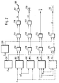
- Figure 2 shows a block diagram of the control system according to the invention.
- Set four maps 200, 202, 204 and 206 A setpoint value is provided at its output, the map 200 provides a setpoint ⁇ DKS for the throttle valve angle, the map 202 a setpoint BVS for the opening degree of the bypass valve 120, the map 204 a setpoint ⁇ ZS for the ignition angle and the map 206 a setpoint tiS for the injection time.
- map 206 in the system according to the invention is optional.
- the map 206 and the blocks that process the output signal of the map 206 and the associated connecting lines are therefore shown in dashed lines.
- the map 200 has two inputs, a signal n for the speed of the internal combustion engine 100 being present at the first input and a signal ⁇ P from the pedal value transmitter 128 at the second input.
- the map 202 also has two inputs and the same signals are present as on the map 200 .
- the map 204 has three inputs, the signal n for the speed of the internal combustion engine 100 being present at a first input, a signal L for the load at a second input and a signal TL for the intake air temperature at a third input.
- the map 206 also has three inputs and the same signals are present as on the map 204.
- the outputs of the characteristic diagrams 200, 202, 204 and 206 are each connected to an input of a block, in which a correction or an adaptation of the setpoint value output by the corresponding characteristic diagram takes place depending on the occurrence of knocking combustion.
- the output of the map 200 is connected to an input of a block 208, the output of the map 202 to an input of a block 210, the output of the map 204 to one Input of a block 212 and the output of the map 206 with an input of a block 214.
- the blocks 208, 210, 212 and 214 each have at least one further input. These further inputs are connected to one another and to the output of a knock control stage 216.
- the signal K emitted by knock sensor 122 is present at the input of knock control stage.
- the knock control stage 216 can influence the target values ⁇ DKS, BVS, ⁇ ZS and tiS via blocks 208, 210, 212 and 214.
- the influencing can take place via a common connecting line or else via separate connecting lines, one for each block. Only one setpoint can be influenced or several setpoints can be influenced at the same time. The influence will usually be such that knocking combustion is counteracted. The person skilled in the art knows how to influence the setpoints in detail in order to counteract knocking combustion.
- block 214 has a further input at which a signal from a lambda control known per se is present.
- the setpoints, possibly corrected, output by blocks 208, 210, 212 and 214 are fed into a further correction block.
- the output of block 208 is connected to a first input of a correction block 218, the output of block 210 to a first input of a correction block 220, the output of block 212 to a first input of a correction block 224 and the output of block 214 to a first Input of a correction block 226.
- the target values are corrected depending on the slip occurring on the vehicle wheels. This is done in a second Input of the correction blocks 218, 220, 224 and 226 fed the output signal of a traction control stage 228.
- the target values are corrected in such a way that any slip that may occur on the vehicle wheels does not exceed a permissible maximum dimension or assume a desired value. This can be achieved by correcting a single setpoint or by simultaneously correcting multiple setpoints.
- the control of the correction blocks 218, 220, 224 and 226 by the traction control stage 228 can take place either - as shown in FIG. 2 - via a common line or via separate lines. The person skilled in the art knows how to correct each individual setpoint value.
- the correction blocks 218, 220, 224 and 226 either directly output an actuating signal to control the corresponding actuators (control) or they output the corrected setpoints to downstream controllers, which ultimately determine the actuating signals by comparison with actual values (control).
- the correction block 224 outputs an actuating signal for actuating the spark plugs and the correction block 226 an actuating signal for actuating the injection nozzle or the injection nozzles 113.
- the correction block 218 outputs a corrected setpoint to a subsequent controller 230.
- Correction block 220 also outputs a corrected setpoint, to a subsequent controller 232. Controller 230 and controller 232 each have an additional input to which the corresponding actual value is present.
- the controller 230 determines an actuating signal DK for controlling the drive 107 for the throttle valve 106 and the Regulator 232 an actuating signal BV for controlling the bypass valve 120.
- the regulators 230 and 232 can also be omitted and the corresponding actuating signals can then be output directly by the correction blocks 218 and 220, respectively.
- An essential point of the invention consists in the coordinated control of the throttle valve 106 and the bypass valve 120.
- the coordinated control enables the efficiency of the internal combustion engine 100 to be increased.
- the increase in efficiency is achieved by appropriate dimensioning of the maps 200 and 202.
- the characteristic diagrams 200 and 202 are dimensioned such that in a first operating state of the internal combustion engine 100 the bypass valve 120 is controlled into an open position and the power output of the internal combustion engine is controlled or regulated via the throttle valve 106 (suction operation). In a second operating range of the internal combustion engine, the throttle valve 106 is controlled into an open position and the power output of the internal combustion engine 100 is controlled or regulated by actuating the bypass valve 120 (supercharging operation).
- the map 202 outputs a setpoint BVS, which ultimately leads to the bypass valve 120 being controlled into an open position, and the map 200 outputs a setpoint ⁇ DKS, which at the present speed n the implemented by the pedal angle ⁇ P driver request by appropriate control of the throttle valve 106.
- the map 200 outputs a setpoint value ⁇ DKS, which leads to an open position of the throttle valve 106, and the map 202 outputs a setpoint value BVS, which, at the present speed n, converts the driver's request expressed by the pedal travel ⁇ P into a corresponding control signal for the bypass valve 120.
- the division into two operating areas prevents, for example, a high boost pressure generated by closing the bypass valve 120 being severely throttled by a closed or only slightly opened throttle valve 106, which would lead to losses. Furthermore, in operating areas in which the driver's request can be implemented solely by correspondingly controlling the throttle valve, the operation of the turbocharger is dispensed with and energy is thus saved, that is to say the bypass valve 120 is opened.
- the first operating range, the suction mode, is usually at low speeds n and small values for the accelerator pedal travel ⁇ P
- the second operating range, the charging mode at high values for n and ⁇ P.
- a transition range can also be defined between the two operating ranges, in which the setpoints ⁇ DKS and BVS stored in the characteristic diagrams 200 and 202 are dimensioned such that a transition from power control or power control by means of throttle valve 106 to power control or power control by means of bypass valve 120 takes place, that is, the throttle valve 106 and the bypass valve 120 are partially open.
- the influencing of the desired values output by the characteristic diagrams 200, 202, 204 and 206 in dependence on the output signals of the knock control stage 216 serves to protect the internal combustion engine 100 from damage by knocking combustion. If such knocking combustion is recognized by knock control stage 216, knocking can be counteracted by influencing the desired values accordingly.
- An effective countermeasure is possible in all operating areas of the internal combustion engine, since it can take place via four different intervention paths, namely via the throttle valve 106, via the bypass valve 120, via the ignition system and via the injection valve or the injection valves 113. The same applies to measures for limiting or optimizing the wheel slip, which are initiated by the traction control stage 228.
- the setpoints are influenced either individually or together, so that the throttle valve 106, the bypass valve 120, the ignition system and the injection valve or the injection valves 113 are available as engagement paths.
- control system offers a very efficient power control or power regulation of the internal combustion engine by coordinated control of the throttle valve 106 and the bypass valve 120.
- the matching is realized by appropriate dimensioning of the setpoints ⁇ DKS or BVS provided for these two actuators.
- these target values are influenced depending on the occurrence of knocking combustion and depending on the wheel slip.
- the setpoints can either be used to control the actuators or by adding actual values to a corresponding control. Interventions in the ignition and / or the injection are also provided depending on the occurrence of knocking combustion and the wheel slip.
Landscapes
- Engineering & Computer Science (AREA)
- Chemical & Material Sciences (AREA)
- Combustion & Propulsion (AREA)
- Mechanical Engineering (AREA)
- General Engineering & Computer Science (AREA)
- Transportation (AREA)
- Control Of Vehicle Engines Or Engines For Specific Uses (AREA)
- Electrical Control Of Air Or Fuel Supplied To Internal-Combustion Engine (AREA)
- Output Control And Ontrol Of Special Type Engine (AREA)
- Control Of Throttle Valves Provided In The Intake System Or In The Exhaust System (AREA)
- Combined Controls Of Internal Combustion Engines (AREA)
- Supercharger (AREA)
Abstract
Description
- Die Erfindung betrifft ein System zur Leistungssteuerung oder Leistungsregelung einer aufgeladenen Brennkraftmaschine gemaß dem Oberbegriff des Anspruchs 1.
- Aus der DE 32 41 024 C2 ist ein Verfahren zur bedarfsabhängigen Ladersteuerung bekannt, bei dem eine Ladereinrichtung abhängig von der Gaspedalstellung zuschaltbar ist. Durch das Zuschalten der Ladereinrichtung kann die Motorleistung erhöht werden, das heißt, es kann im Bedarfsfall zusätzliche Motorleistung zur Verfügung gestellt werden.
- Der Erfindung liegt die Aufgabe zugrunde, eine möglichst optimale Steuerung bzw. Regelung einer aufgeladenen Brennkraftmaschine zu ermöglichen. Insbesondere soll der Fahrerwunsch durch Einbeziehung mehrerer leistungsbeeinflussender Elemente möglichst optimal umgesetzt werden.
- Das erfindungsgemäße Steuersystem bzw. Regelsystem hat den Vorteil, daß es eine sehr gute Steuerung bzw. Regelung der Leistung einer aufgeladenen Brennkraftmaschine ermöglicht, in deren Ansaugtrakt ein Verdichter angeordnet ist, der von einer Turbine im Abgaskanal angetrieben wird. In einem ersten Betriebsbereich der Brennkraftmaschine erfolgt die Leistungssteuerung oder Leistungsregelung hauptsächlich mittels einer Drosselklappe, die im Ansaugtrakt der Brennkraftmaschine angeordnet ist. In einem zweiten Betriebsbereich der Brennkraftmaschine erfolgt die Leistungssteuerung oder Leistungsregelung hauptsächlich mittels eines Bypass-Ventils, das in einer Umgehungsleitung zur Turbine angebracht ist. Durch eine derart aufeinander abgestimmte Betätigung der leistungsbeeinflussenden Elemente Drosselklappe und Bypass-Ventil wird ein hoher Wirkungsgrad der Brennkraftmaschine erreicht.
- Besonders vorteilhaft ist auch, daß die Leistungssteuerung oder Leistungsregelung abhängig vom Radschlupf beeinflußbar ist und somit sichergestellt wird, daß von der Brennkraftmaschine nur soviel Leistung abgegeben wird, wie unter den gegebenen Betriebs- und Fahrbahnbedingungen zum Antrieb des Fahrzeugs genutzt werden kann. Dadurch läßt sich unter verschiedenen Betriebs- und Fahrbahnbedingungen jeweils eine optimale Beschleunigung und Bodenhaftung erzielen und gleichzeitig sind ein hoher Wirkungsgrad und niedriger Kraftstoffverbrauch sichergestellt.
- Die obengenannte Beeinflussung der Leistungssteuerung oder Leistungsregelung erfolgt in der Regel durch Korrektureingriffe auf die Sollwerte für den Drosselklappenwinkel und den Öffnungsgrad des Bypass-Ventils. Es können aber auch andere leistungsbeeinflussenden Elemente wie Zündung oder Einspritzung einbezogen werden.
- Weiterhin kann noch eine Beeinflussung der Leistungssteuerung bzw. Leistungsregelung abhängig vom Auftreten klopfender Verbrennung vorgesehen sein, um die Brennkraftmaschine vor Beschädigung zu schützen.
- Die Betriebsbereiche werden abhängig von der Drehzahl der Brennkraftmaschine und der Fahrpedalstellung vorgegeben.
- Die Erfindung wird nachstehend anhand der in der Zeichnung dargestellten Ausführungsbeispiele erläutert.
- Es zeigen
- Figur 1 das technische Umfeld, in dem die Erfindung eingesetzt wird und
- Figur 2 ein Blockschaltbild des erfindungsgemäßen Steuersystems.
- Figur 1 zeigt eine Brennkraftmaschine 100 mit einem Ansaugtrakt 102 und einem Abgaskanal 104. Im Ansaugtrakt 102 sind - in Stromrichtung der angesaugten Luft gesehen - ein Luftmengen- oder Luftmassenmesser 105, ein Verdichter 108, eine Drosselklappe 106, die mit einem Antrieb 107 verbunden ist, ein Temperatursensor 110 zur Erfassung der Temperatur TL der von der Brennkraftmaschine 100 angesaugten Luft, ein Drucksensor 112 zur Erfassung des Ladedrucks P und eine oder mehrere Einspritzdüsen 113 angeordnet. Der Verdichter 108 wird über ein Verbindungsmittel 114 von einer im Abgaskanal 104 angeordneten Turbine 116 angetrieben. Eine Bypass-Leitung 118 führt um die Turbine 116 herum. In der Bypass-Leitung 118 ist ein Bypass-Ventil 120 angeordnet. An der Brennkraftmaschine 100 sind ein Klopfsensor 122, der bei einer klopfenden Verbrennung ein Klopfsignal K abgibt, ein Drehzahlsensor 123 zur Erfassung der Drehzahl n der Brennkraftmaschine 100 und ein Temperatursensor 124 zur Erfassung der Temperatur TKM des Kühlmittels angebracht. Die Brennkraftmaschine 100 besitzt beispielsweise vier Zylinder 125, die mit je einer Zündkerze bestückt sind.
- Sämtliche Sensoren sind mit einem zentralen Steuergerät 126 verbunden. Weiterhin ist das zentrale Steuergerät 126 mit der Drosselklappe 106, dem Antrieb 107, der Einspritzdüse bzw. den Einspritzdüsen 113, dem Bypass-Ventil 120, den Zündkerzen, einem Pedalwertgeber 128 zur Erfassung der Fahrpedalstellung und einer Einrichtung 130 zur Ermittlung des Radschlupfs des Fahrzeugs verbunden. Im einzelnen wird das Steuergerät mit folgenden Signalen beaufschlagt: Ein Signal L des Luftmengen- oder Luftmassenmessers 105 oder ein Signal P des Drucksensors 112, ein Signal αDK der Drosselklappe 106, ein Signal TL des Temperatursensors 110, ein Signal K des Klopfsensors 122, ein Signal n des Drehzahlsensors 123, ein Signal TKM des Temperatursensors 124, ein Signal αP des Pedalwertgebers 128 und ein Schlupfsignal S, das von der Einrichtung 130 zur Ermittlung des Radschlupfs erzeugt wird. Ausgegeben werden vom Steuergerät 126 ein Signal DK an den Antrieb 107, ein Signal ti an die Einspritzdüse bzw. die Einspritzdüsen 113, ein Signal BV an das Bypass-Ventil 120 und Hochspannungssignale an die Zündkerzen.
- Figur 2 zeigt ein Blockschaltbild des erfindungsgemäßen Steuersystems. Vier Kennfelder 200, 202, 204 und 206 stellen an ihrem Ausgang jeweils einen Sollwert bereit, wobei das Kennfeld 200 einen Sollwert αDKS für den Drosselklappenwinkel bereitstellt, das Kennfeld 202 einen Sollwert BVS für den Öffnungsgrad des Bypass-Ventils 120, das Kennfeld 204 einen Sollwert αZS für den Zündwinkel und das Kennfeld 206 einen Sollwert tiS für die Einspritzzeit.
- Die Einbeziehung des Kennfelds 206 in das erfindungsgemäße System ist optional. Deshalb sind das Kennfeld 206 und die Blöcke, die das Ausgangssignal des Kennfelds 206 weiterverarbeiten sowie die dazugehörigen Verbindungsleitungen gestrichelt dargestellt.
- Das Kennfeld 200 besitzt zwei Eingänge, wobei am ersten Eingang ein Signal n für die Drehzahl der Brennkraftmaschine 100 anliegt und am zweiten Eingang ein Signal αP des Pedalwertgebers 128. Das Kennfeld 202 besitzt ebenfalls zwei Eingänge und es liegen die gleichen Signale wie am Kennfeld 200 an. Das Kennfeld 204 besitzt drei Eingänge, wobei an einem ersten Eingang das Signal n für die Drehzahl der Brennkraftmaschine 100 anliegt, an einem zweiten Eingang ein Signal L für die Last und an einem dritten Eingang ein Signal TL für die Ansauglufttemperatur. Das Kennfeld 206 besitzt ebenfalls drei Eingänge und es liegen die gleichen Signale wie am Kennfeld 204 an.
- Die Ausgänge der Kennfelder 200, 202, 204 und 206 sind jeweils mit einem Eingang je eines Blocks verbunden, in dem eine Korrektur oder eine Adaption des vom entsprechenden Kennfeld ausgegebenen Sollwerts abhängig vom Auftreten klopfender Verbrennung stattfindet. Mit anderen Worten, der Ausgang des Kennfelds 200 ist mit einem Eingang eines Blocks 208 verbunden, der Ausgang des Kennfelds 202 mit einem Eingang eines Blocks 210, der Ausgang des Kennfelds 204 mit einem Eingang eines Blocks 212 und der Ausgang des Kennfelds 206 mit einem Eingang eines Blocks 214. Die Blöcke 208, 210, 212 und 214 besitzen jeweils noch wenigstens einen weiteren Eingang. Diese weiteren Eingänge sind miteinander und mit dem Ausgang einer Klopfregelstufe 216 verbunden.
- Am Eingang der Klopfregelstufe liegt das vom Klopfsensor 122 abgegebene Signal K an. Abhängig von diesem Signal K kann die Klopfregelstufe 216 über die Blöcke 208, 210, 212 und 214 die Sollwerte αDKS, BVS, αZS und tiS beeinflussen. Die Beeinflussung kann - wie in Figur 2 dargestellt - über eine gemeinsame Verbindungsleitung erfolgen oder aber auch über getrennte Verbindungsleitungen, für jeden Block eine. Dabei kann nur ein einziger Sollwert beeinflußt werden oder es können mehrere Sollwerte gleichzeitig beeinflußt werden. Die Beeinflussung wird in der Regel derart erfolgen, daß einer klopfenden Verbrennung entgegengewirkt wird. Wie die Sollwerte im einzelnen zu beeinflussen sind, um einer klopfenden Verbrennung entgegenzuwirken, ist dem Fachmann bekannt. Zusätzlich zu den beiden bereits beschriebenen Eingängen besitzt der Block 214 einen weiteren Eingang, an dem ein Signal einer für sich bekannten Lambdaregelung anliegt.
- Die von den Blöcken 208, 210, 212 und 214 ausgegebenen, ggf. korrigierten Sollwerte werden in je einen weiteren Korrekturblock eingespeist. Dazu ist der Ausgang des Blocks 208 mit einem ersten Eingang eines Korrekturblocks 218 verbunden, der Ausgang des Blocks 210 mit einem ersten Eingang eines Korrekturblocks 220, der Ausgang des Blocks 212 mit einem ersten Eingang eines Korrekturblocks 224 und der Ausgang des Blocks 214 mit einem ersten Eingang eines Korrekturblocks 226. In den Korrekturblöcken 218, 220, 224 und 226 werden die Sollwerte abhängig von an den Fahrzeugrädern auftretendem Schlupf korrigiert. Dazu wird in je einen zweiten Eingang der Korrekturblöcke 218, 220, 224 und 226 das Ausgangssignal einer Antriebsschlupfregelstufe 228 eingespeist. Am Eingang der Antriebsschlupfregelstufe 228 liegt das vom Block 130 der Figur 1 ausgegebene Schlupfsignal S an. In den Korrekturblöcken 218, 220, 224 und 226 werden die Sollwerte derart korrigiert, daß ggf. auftretender Schlupf an den Fahrzeugrädern ein zulässiges Höchstmaß nicht überschreitet bzw. einen gewünschten Wert annimmt. Dies kann durch Korrektur eines einzigen Sollwerts oder durch gleichzeitige Korrektur mehrerer Sollwerte erreicht werden. Die Ansteuerung der Korrekturblöcke 218, 220, 224 und 226 durch die Antriebsschlupfregelstufe 228 kann entweder - wie in Figur 2 dargestellt - über eine gemeinsame Leitung oder über getrennte Leitungen erfolgen. Wie jeder einzelne Sollwerte dabei zu korrigieren ist, ist dem Fachmann bekannt.
- Je nach Ausführungsbeispiel geben die Korrekturblöcke 218, 220, 224 und 226 entweder direkt ein Stellsignal zur Ansteuerung der entsprechenden Stellglieder aus (Steuerung) oder sie geben die korrigierten Sollwerte an nachgeschaltete Regler aus, die durch Vergleich mit Istwerten letztendlich die Stellsignale ermitteln (Regelung). In dem in Figur 2 dargestellten Ausführungsbeispiel gibt der Korrekturblock 224 ein Stellsignal zur Ansteuerung der Zündkerzen aus und der Korrekturblock 226 ein Stellsignal zur Ansteuerung der Einspritzdüse bzw. der Einspritzdüsen 113. Der Korrekturblock 218 gibt einen korrigierten Sollwert an einen nachfolgenden Regler 230 aus. Der Korrekturblock 220 gibt ebenfalls einen korrigierten Sollwert aus, und zwar an einen nachfolgenden Regler 232. Der Regler 230 und der Regler 232 besitzen je einen zusätzlichen Eingang, an dem der entsprechende Istwert anliegt. Aus dem Vergleich zwischen Soll- und Istwert ermittelt der Regler 230 ein Stellsignal DK zur Ansteuerung des Antriebs 107 für die Drosselklappe 106 und der Regler 232 ein Stellsignal BV zur Ansteuerung des Bypass-Ventils 120. Je nach Ausführungsbeispiel können die Regler 230 und 232 auch entfallen und die entsprechenden Stellsignale können von den Korrekturblöcken 218 bzw. 220 dann direkt ausgegeben werden.
- Ein wesentlicher Punkt der Erfindung besteht in der aufeinander abgestimmten Ansteuerung der Drosselklappe 106 und des Bypass-Ventils 120. Durch die abgestimmte Ansteuerung läßt sich der Wirkungsgrad der Brennkraftmaschine 100 steigern. Die Wirkungsgradsteigerung wird durch eine entsprechende Dimenisionierung der Kennfelder 200 und 202 erreicht. Die Kennfelder 200 und 202 werden so dimensioniert, daß in einem ersten Betriebszustand der Brennkraftmaschine 100 das Bypass-Ventil 120 in eine geöffnete Stellung gesteuert wird und die Leistungsabgabe der Brennkraftmaschine über die Drosselklappe 106 gesteuert oder geregelt wird (Saugbetrieb). In einem zweiten Betriebsbereich der Brennkraftmaschine wird die Drosselklappe 106 in eine geöffnete Stellung gesteuert und die Leistungsabgabe der Brennkraftmaschine 100 wird durch Ansteuerung des Bypass-Ventils 120 gesteuert oder geregelt (Aufladebetrieb). Mit anderen Worten, im ersten Betriebsbereich gibt das Kennfeld 202 einen Sollwert BVS ab, der letztendlich dazu führt, daß das Bypass-Ventil 120 in eine geöffnete Stellung gesteuert wird und das Kennfeld 200 gibt einen Sollwert αDKS ab, der bei der vorliegenden Drehzahl n den durch den Pedalwinkel αP ausgedrückten Fahrerwunsch durch entsprechende Ansteuerung der Drosselklappe 106 umsetzt. Umgekehrt gibt im zweiten Betriebsbereich das Kennfeld 200 einen Sollwert αDKS ab, der zu einer geöffneten Stellung der Drosselklappe 106 führt und das Kennfeld 202 gibt einen Sollwert BVS ab, der bei der vorliegenden Drehzahl n den durch den Pedalweg αP ausgedrückten Fahrerwunsch in ein entsprechendes Ansteuersignal für das Bypass-Ventil 120 umsetzt. Durch die Aufteilung in zwei Betriebsbereiche wird verhindert, daß beispielsweise ein durch Schließen des Bypass-Ventils 120 erzeugter hoher Ladedruck durch eine geschlossene oder nur wenig geöffnete Drosselklappe 106 stark gedrosselt wird, was zu Verlusten führen würde. Weiterhin wird in Betriebsbereichen, in denen sich der Fahrerwunsch allein durch entsprechende Ansteuerung der Drosselklappe umsetzen läßt, auf den Betrieb des Turboladers verzichtet und somit Energie gespart, das heißt, das Bypass-Ventil 120 wird geöffnet.
- Der erste Betriebsbereich, der Saugbetrieb, liegt in der Regel bei niedrigen Drehzahlen n und kleinen Werten für den Fahrpedalweg αP, der zweite Betriebsbereich, der Aufladebetrieb, bei hohen Werten für n und αP. Zwischen den beiden Betriebsbereichen kann noch ein Übergangsbereich definiert sein, in dem die in den Kennfelern 200 und 202 abgelegten Sollwerte αDKS und BVS so dimensioniert sind, daß ein Übergang von der Leistungssteuerung oder Leistungsregelung mittels Drosselklappe 106 auf eine Leistungssteuerung oder Leistungsregelung mittels Bypass-Ventil 120 stattfindet, das heißt, die Drosselklappe 106 und das Bypass-Ventil 120 sind teilweise geöffnet.
- Die Beeinflussung der von den Kennfeldern 200, 202, 204 und 206 ausgegebenen Sollwerte in Abhängigkeit der Ausgangssignale der Klopfregelstufe 216 dient dem Schutz der Brennkraftmaschine 100 vor Beschädigung durch klopfende Verbrennung. Falls von der Klopfregelstufe 216 eine solche klopfende Verbrennung erkannt wird, kann dem Klopfen durch entsprechende Beeinflussung der Sollwerte entgegengewirkt werden. Eine effektive Gegensteuerungn ist in allen Betriebsbereichen der Brennkraftmaschine möglich, da sie über vier verschiedene Eingriffspfade erfolgen kann, nämlich über die Drosselklappe 106, über das Bypass-Ventil 120, über die Zündanlage und über das Einspritzventil oder die Einspritzventile 113. Das gleiche gilt für Maßnahmen zur Begrenzung oder Optimierung des Radschlupfs, die von der Antriebsschlupfregelstufe 228 eingeleitet werden. Auch hier werden die Sollwerte entweder einzeln oder gemeinsam beeinflußt, so daß als Eingriffspfade die Drosselklappe 106 das Bypass-Ventil 120, die Zündanlage und das Einspritzventil bzw. die Einspritzventile 113 zur Verfügung stehen.
- Insgesamt bietet das erfindungsgemäße Steuersystem eine sehr effiziente Leistungssteuerung oder Leistungsregelung der Brennkraftmaschine durch aufeinanderabgestimmte Ansteuerung der Drosselklappe 106 und des Bypass-Ventils 120. Die Abstimmung ist durch entsprechende Dimensionierung der für diese beiden Stellglieder vorgesehenen Sollwerte αDKS bzw. BVS realisiert. Weiterhin ist eine Beeinflussung dieser Sollwerte abhängig vom Auftreten klopfender Verbrennung und abhängig vom Radschlupf vorgesehen. Die Sollwerte können entweder zur Steuerung der Stellglieder oder unter Hinzunahme von Istwerten zu einer entsprechenden Regelung verwendet werden. Weiterhin sind noch Eingriffe in die Zündung und/oder die Einspritzung abhängig vom Auftreten klopfender Verbrennung und vom Radschlupf vorgesehen.
Claims (11)
- System zur Leistungssteuerung oder Leistungsregelung einer aufgeladenen Brennkraftmaschine (100), in deren Ansaugtrakt (102) ein Verdichter (108) angeordnet ist, der von einer Turbine (116) im Abgaskanal (104) angetrieben wird, dadurch gekennzeichnet, daß- in einem ersten Betriebsbereich der Brennkraftmaschine (100) die Leistungssteuerung oder Leistungsregelung hauptsächlich mittels einer Drosselklappe (106) erfolgt, die im Ansaugtrakt (102) der Brennkraftmaschine (100) angeordnet ist,- in einem zweiten Betriebsbereich der Brennkraftmaschine (100) die Leistungssteuerung oder Leistungsregelung hauptsächlich mittels eines Bypass-Ventils (120) erfolgt, das in einer Umgehungsleitung (118) zur Turbine (116) angeordnet ist und- die Leistungssteuerung oder Leistungsregelung abhängig von einem den Radschlupf angebenden Signal S beeinflußbar ist.
- System nach Anspruch 1, dadurch gekennzeichnet, daß im ersten Betriebsbereich der Brennkraftmaschine (100) das Bypass-Ventil (120) in eine geöffnete Stellung gesteuert wird und die Leistungssteuerung oder Leistungsregelung mittels der Drosselklappe (106) erfolgt.
- System nach Anspruch 1, dadurch gekennzeichnet, daß im zweiten Betriebsbereich der Brennkraftmaschine (100) die Drosselklappe (106) in eine geöffnete Stellung gesteuert wird und die Leistungssteuerung oder Leistungsregelung mittels des Bypass-Ventils (120) erfolgt.
- System nach einem der vorhergehenden Ansprüche, dadurch gekennzeichnet, daß in einem dritten Betriebsbereich der Brennkraftmaschine (100) ein Übergang zwischen der Leistungssteuerung oder Leistungsregelung mittels der Drosselklappe (106) und der Leistungssteuerung oder Leistungsregelung mittels des Bypass-Ventils (120) erfolgt.
- System nach einem der vorhergehenden Ansprüche, dadurch gekennzeichnet, daß ein Sollwert αDKS für den Drosselklappenwinkel abhängig von der Drehzahl n und der Fahrpedalstellung αP von einem Kennfeld (200) ausgegeben wird, wobei das Kennfeld (200) so dimensioniert ist, daß der im ersten Betriebsbereich der Brennkraftmaschine (100) ausgegebene Sollwert αDKS die Drosselklappe (106) in eine der Drehzahl n und der Fahrpedalstellung αP entsprechende Stellung steuert und der im zweiten Betriebsbereich der Brennkraftmaschine (100) ausgegebene Sollwert αDKS die Drosselklappe (106) in eine geöffnete Stellung steuert.
- System nach einem der vorhergehenden Ansprüche, dadurch gekennzeichnet, daß ein Kennfeld (202) in Abhängigkeit von der Fahrpedalstellung αP und der Drehzahl n einen Sollwert BVS für das Bypass-Ventil (120) ausgibt, wobei das Kennfeld (202) so dimensioniert ist, daß es im ersten Betriebsbereich der Brennkraftmaschine (100) einen Sollwert BVS ausgibt, der das Bypass-Ventil (120) in eine geöffnete Stellung steuert und im zweiten Betriebsbereich der Brennkraftmaschine (100) einen Sollwert BVS ausgibt, der das Bypass-Ventil (120) in eine der Drehzahl n und der Fahrpedalstellung αP entsprechende Stellung steuert.
- System nach einem der vorhergehenden Ansprüche, dadurch gekennzeichnet, daß der Sollwert αDKS und/oder der Sollwert BVS abhängig vom Auftreten klopfender Verbrennung beeinflußbar sind/ist.
- System nach einem der vorhergehenden Ansprüche, dadurch gekennzeichnet, daß der Sollwert αDKS und/oder der Sollwert BVS abhängig vom Radschlupf beeinflußbar sind/ist werden.
- System nach einem der vorhergehenden Ansprüche, dadurch gekennzeichnet, daß die Betriebsbereiche der Brennkraftmaschine (100) abhängig von der Drehzahl n und der Fahrpedalstellung αP vorgebbar sind.
- System nach einem der vorhergehenden Ansprüche, dadurch gekennzeichnet, daß der erste Betriebsbereich der Brennkraftmaschine (100) bei kleinen Werten für die Drehzahl n und die Fahrpedalstellung αP vorliegt und der zweite Betriebsbereich bei großen Werten für die Drehzahl n und die Fahrpedalstellung αP vorliegt.
- System nach einem der Ansprüche 4 bis 10, dadurch gekennzeichnet, daß der dritte Betriebsbereich der Brennkraftmaschine (100) zwischen dem ersten und dem zweiten Betriebsbereich liegt.
Applications Claiming Priority (2)
| Application Number | Priority Date | Filing Date | Title |
|---|---|---|---|
| DE4417647 | 1994-05-20 | ||
| DE4417647A DE4417647A1 (de) | 1994-05-20 | 1994-05-20 | System zur Leistungssteuerung oder Leistungsregelung einer aufgeladenen Brennkraftmaschine |
Publications (2)
| Publication Number | Publication Date |
|---|---|
| EP0683308A2 true EP0683308A2 (de) | 1995-11-22 |
| EP0683308A3 EP0683308A3 (de) | 1998-05-20 |
Family
ID=6518537
Family Applications (1)
| Application Number | Title | Priority Date | Filing Date |
|---|---|---|---|
| EP95105576A Withdrawn EP0683308A3 (de) | 1994-05-20 | 1995-04-13 | System zur Leistungssteuerung oder Leistungsregelung einer aufgeladenen Brennkraftmaschine |
Country Status (3)
| Country | Link |
|---|---|
| EP (1) | EP0683308A3 (de) |
| JP (1) | JPH07317575A (de) |
| DE (1) | DE4417647A1 (de) |
Cited By (4)
| Publication number | Priority date | Publication date | Assignee | Title |
|---|---|---|---|---|
| WO1997033081A1 (de) * | 1996-03-06 | 1997-09-12 | Robert Bosch Gmbh | Verfahren und anordnung zum steuern oder regeln der leistung einer aufladbaren brennkraftmaschine |
| WO2002004799A1 (de) * | 2000-07-07 | 2002-01-17 | Siemens Aktiengesellschaft | Verfahren zur regelung eines ladedrucks in einer brennkraftmaschine mit einem abgasturbolader |
| WO2004099594A1 (fr) * | 2003-05-06 | 2004-11-18 | Siemens Vdo Automotive | Procede et dispositif de gestion du debit d’air alimentant un moteur a combustion interne |
| EP2199582A3 (de) * | 2008-12-19 | 2014-02-19 | Nissan Motor Co., Ltd. | Vorrichtung zur Steuerung der Motoransaugmenge |
Families Citing this family (4)
| Publication number | Priority date | Publication date | Assignee | Title |
|---|---|---|---|---|
| US5361823A (en) * | 1992-07-27 | 1994-11-08 | Cmi International, Inc. | Casting core and method for cast-in-place attachment of a cylinder liner to a cylinder block |
| DE19732642C2 (de) * | 1997-07-29 | 2001-04-19 | Siemens Ag | Einrichtung zum Steuern einer Brennkraftmaschine |
| US6957140B1 (en) * | 2004-07-14 | 2005-10-18 | General Motors Corporation | Learned airflow variation |
| DE102010043897B4 (de) | 2010-11-15 | 2022-12-01 | Robert Bosch Gmbh | Verfahren und Vorrichtung zum Betreiben eines Verbrennungsmotors |
Citations (5)
| Publication number | Priority date | Publication date | Assignee | Title |
|---|---|---|---|---|
| GB2078856A (en) * | 1980-07-04 | 1982-01-13 | Hitachi Ltd | Turbocharger control system for use in internal combustion engines |
| GB2105878A (en) * | 1981-09-09 | 1983-03-30 | Porsche Ag | Load regulation of an internal combustion engine supercharged with an exhaust gas turbocharger |
| US4432430A (en) * | 1981-06-29 | 1984-02-21 | Ab Volvo | Wheel spinning control system for motor vehicles |
| US4620420A (en) * | 1983-12-12 | 1986-11-04 | Robert Bosch Gmbh | Device for reducing drive slip of motor vehicles provided with turbo charged engines |
| EP0450787A2 (de) * | 1990-04-04 | 1991-10-09 | Lucas Industries Public Limited Company | Verfahren und System zur Steuerung von Brennkraftmaschinen |
-
1994
- 1994-05-20 DE DE4417647A patent/DE4417647A1/de not_active Withdrawn
-
1995
- 1995-04-13 EP EP95105576A patent/EP0683308A3/de not_active Withdrawn
- 1995-05-19 JP JP7121876A patent/JPH07317575A/ja active Pending
Patent Citations (5)
| Publication number | Priority date | Publication date | Assignee | Title |
|---|---|---|---|---|
| GB2078856A (en) * | 1980-07-04 | 1982-01-13 | Hitachi Ltd | Turbocharger control system for use in internal combustion engines |
| US4432430A (en) * | 1981-06-29 | 1984-02-21 | Ab Volvo | Wheel spinning control system for motor vehicles |
| GB2105878A (en) * | 1981-09-09 | 1983-03-30 | Porsche Ag | Load regulation of an internal combustion engine supercharged with an exhaust gas turbocharger |
| US4620420A (en) * | 1983-12-12 | 1986-11-04 | Robert Bosch Gmbh | Device for reducing drive slip of motor vehicles provided with turbo charged engines |
| EP0450787A2 (de) * | 1990-04-04 | 1991-10-09 | Lucas Industries Public Limited Company | Verfahren und System zur Steuerung von Brennkraftmaschinen |
Cited By (6)
| Publication number | Priority date | Publication date | Assignee | Title |
|---|---|---|---|---|
| WO1997033081A1 (de) * | 1996-03-06 | 1997-09-12 | Robert Bosch Gmbh | Verfahren und anordnung zum steuern oder regeln der leistung einer aufladbaren brennkraftmaschine |
| WO2002004799A1 (de) * | 2000-07-07 | 2002-01-17 | Siemens Aktiengesellschaft | Verfahren zur regelung eines ladedrucks in einer brennkraftmaschine mit einem abgasturbolader |
| US6732523B2 (en) | 2000-07-07 | 2004-05-11 | Siemens Aktiengesellschaft | Method for controlling a charge pressure in an internal combustion engine with an exhaust gas turbocharger |
| WO2004099594A1 (fr) * | 2003-05-06 | 2004-11-18 | Siemens Vdo Automotive | Procede et dispositif de gestion du debit d’air alimentant un moteur a combustion interne |
| US7426828B2 (en) | 2003-05-06 | 2008-09-23 | Continental Automotive France | Method and device for controlling the airflow supplied to an internal combustion engine |
| EP2199582A3 (de) * | 2008-12-19 | 2014-02-19 | Nissan Motor Co., Ltd. | Vorrichtung zur Steuerung der Motoransaugmenge |
Also Published As
| Publication number | Publication date |
|---|---|
| DE4417647A1 (de) | 1995-11-23 |
| EP0683308A3 (de) | 1998-05-20 |
| JPH07317575A (ja) | 1995-12-05 |
Similar Documents
| Publication | Publication Date | Title |
|---|---|---|
| DE3303350C2 (de) | Steuervorrichtung für den Ladedruck einer Brennkraftmaschine mit Turbolader | |
| DE2823255C2 (de) | Vorrichtung zur Bestimmung der Aufladung einer abgasturbogeladenen Brennkraftmaschine | |
| EP1375868B1 (de) | Motorbremseinrichtung für eine turboaufgeladene Brennkraftmaschine | |
| EP1179128B1 (de) | Verfahren und vorrichtung zur regelung des ladedrucks einer brennkraftmaschine | |
| EP0084037B2 (de) | Einrichtung zum steueren des ladedrucks bei einer mit aufladung betriebenen brennkraftmaschine | |
| DE4330368A1 (de) | Verfahren und Vorrichtung zur Steuerung der Antriebsleistung eines Fahrzeugs | |
| DE10314583A1 (de) | Motor mit bedarfsabhängiger Turboladerzuschaltung und Zylinderabschaltung | |
| EP1299628A1 (de) | Verfahren zur regelung eines ladedrucks in einer brennkraftmaschine mit einem abgasturbolader | |
| EP2057362A1 (de) | Einrichtung und verfahren zur frischluftversorgung einer turboaufgeladenen kolbenbrennkraftmaschine | |
| DE102005015609A1 (de) | Vorrichtung zum Steuern einer Brennkraftmaschine | |
| EP0747585A2 (de) | Steuerung für den Ladedruck eines Turboladers an einer Brennkraftmaschine | |
| EP0885353B1 (de) | Verfahren und anordnung zum steuern oder regeln der leistung einer aufladbaren brennkraftmaschine | |
| DE102004028482B4 (de) | Brennkraftmaschine | |
| EP1788220A2 (de) | Verfahren und Steuergerät zur Steuerung eines Turboladers mit turbinenseitiger Ladedruck-Regelung und einem Umluftventil | |
| DE19620778C1 (de) | Verfahren zur Regelung des Druckes im Ansaugkanal einer Brennkraftmaschine und Vorrichtung zur Durchführung des Verfahrens | |
| DE3438176C2 (de) | Einrichtung zur Regelung des Ladedrucks einer Brennkraftmaschine | |
| EP0683308A2 (de) | System zur Leistungssteuerung oder Leistungsregelung einer aufgeladenen Brennkraftmaschine | |
| DE102006022148B4 (de) | Verfahren zur Regelung der einer Brennkraftmaschine zuzuführenden Gesamt-Luftmasse | |
| WO1989011585A1 (fr) | Moteur multicylindre a combustion interne | |
| DE102005023260A1 (de) | Verfahren zur Regelung eines Abgasturboladers | |
| DE4408765A1 (de) | Motorsteuerungssystem | |
| DE19935901B4 (de) | Verfahren und Vorrichtung zur Regelung einer Brennkraftmaschine | |
| DE3719975A1 (de) | Regelsystem fuer eine aufgeladene brennkraftmaschine | |
| WO2000019073A1 (de) | Verfahren zur regelung oder steuerung einer aufgeladenen brennkraftmaschine | |
| DE4435420C1 (de) | Verfahren und Vorrichtung zur Steuerung einer Brennkraftmaschine |
Legal Events
| Date | Code | Title | Description |
|---|---|---|---|
| PUAI | Public reference made under article 153(3) epc to a published international application that has entered the european phase |
Free format text: ORIGINAL CODE: 0009012 |
|
| AK | Designated contracting states |
Kind code of ref document: A2 Designated state(s): DE FR GB SE |
|
| PUAL | Search report despatched |
Free format text: ORIGINAL CODE: 0009013 |
|
| AK | Designated contracting states |
Kind code of ref document: A3 Designated state(s): DE FR GB SE |
|
| 17P | Request for examination filed |
Effective date: 19981120 |
|
| 17Q | First examination report despatched |
Effective date: 20000811 |
|
| STAA | Information on the status of an ep patent application or granted ep patent |
Free format text: STATUS: THE APPLICATION IS DEEMED TO BE WITHDRAWN |
|
| 18D | Application deemed to be withdrawn |
Effective date: 20010222 |