EP0680453B1 - Safety device for a valve insert in a beverage barrel - Google Patents
Safety device for a valve insert in a beverage barrel Download PDFInfo
- Publication number
- EP0680453B1 EP0680453B1 EP93902247A EP93902247A EP0680453B1 EP 0680453 B1 EP0680453 B1 EP 0680453B1 EP 93902247 A EP93902247 A EP 93902247A EP 93902247 A EP93902247 A EP 93902247A EP 0680453 B1 EP0680453 B1 EP 0680453B1
- Authority
- EP
- European Patent Office
- Prior art keywords
- safety device
- base plate
- device defined
- pipe
- compression spring
- Prior art date
- Legal status (The legal status is an assumption and is not a legal conclusion. Google has not performed a legal analysis and makes no representation as to the accuracy of the status listed.)
- Expired - Lifetime
Links
Images


Classifications
-
- B—PERFORMING OPERATIONS; TRANSPORTING
- B67—OPENING, CLOSING OR CLEANING BOTTLES, JARS OR SIMILAR CONTAINERS; LIQUID HANDLING
- B67D—DISPENSING, DELIVERING OR TRANSFERRING LIQUIDS, NOT OTHERWISE PROVIDED FOR
- B67D1/00—Apparatus or devices for dispensing beverages on draught
- B67D1/08—Details
- B67D1/0829—Keg connection means
- B67D1/0831—Keg connection means combined with valves
- B67D1/0838—Keg connection means combined with valves comprising means for preventing blow-out on disassembly of the spear valve
Definitions
- the invention relates to a safety device for a valve insert in an outlet opening of a pressurized beverage keg, in particular a beer keg, with a housing, a riser pipe, a base plate, an external compression spring, which is supported on the one hand on the base plate and on the other hand on a sealing body, and with at least one locking element which is pivotally clamped between the external compression spring and the base plate in such a way that it evades the barrel outlet opening in the axially directed operation and engages behind its inner edge in the operating position.
- Various types of safety devices of the aforementioned type are known in practice. They serve to seal a pressurized beverage keg, in particular a beer keg, after filling and during transport at the outlet opening and to be connected to a dispensing head when the beverage is subsequently filled.
- the safety devices are inserted into the respective outlet opening of the beverage keg.
- the part of the beverage keg simply referred to here as the barrel outlet opening generally has a pipe socket which at least partially projects into the beverage keg and is provided with an internal thread towards the outer upper end, so that the safety device, which is provided with a corresponding external thread , can be screwed tight after use.
- the beverage keg is then subjected to further treatment processes, in particular pressure measurement for leaks, cleaning, etc. until finally the beverage keg at another location, namely at a separate inlet opening with which drinks are filled and then closed.
- the bayonet plate must therefore first be brought into an inclined position through the outlet opening on the inside of the pipe socket and then pivoted into the correct position, after which the actual assembly of the safety device must take place with the bayonet catch, etc.
- manipulations are considered the large number of barrels produced is extremely cumbersome and time-consuming.
- a similar safety device specified at the beginning is known from GB-OS 21 88 040.
- the actual locking element is integrally formed on the bayonet plate in the form of a radially projecting hook.
- a partial assembly of the safety device can be carried out, namely a partial assembly of the central tube with a sealing ring, compression spring and initially a loose bayonet plate. Because of the radial projection of the locking element, the insertion through the outlet opening of the barrel can only take place in the inclined position of the bayonet plate and the central tube.
- the final assembly of the safety device takes place by placing a separate head part with a cylindrical pipe socket, at the inner end of which L-shaped slots are provided, into which radial projections of the bayonet plate must be used. Only then can the safety device be finally screwed into the outlet opening of the drum.
- the assembly processes are quite cumbersome and time-consuming, especially since the compression spring has to be compressed during assembly on the barrel in order to snap the bayonet plate into place.
- the locking element consists of a relatively long, axially extending tongue, at the upper end of which a ring is formed, which in turn is held by the upper end of the compression spring.
- the lower end of the tongue is bent outwards and has a radially outward web. Because of this shape of the locking element, the assembly must also first in an inclined position of the central tube and the surrounding Parts take place before the housing can be straightened, inserted axially and finally screwed down.
- a safety device specified at the beginning is known from DE-A-41 14 604. Although this results in a structurally simple, assemblable and usable device, it has been found that, above all, the removal from the barrel outlet opening is too cumbersome and time-consuming for practice.
- the invention has for its object to provide a safety device that can be brought into the operating position on the one hand in the fully assembled state by simply axially pressing into the barrel outlet opening and by subsequent screwing and on the other hand expanded again as a closed unit by using a special tap head can be.
- the locking element is designed as a double angle piece with an outwardly projecting web, an inclined part and an inner projection that the web in one trapezoidal recess of the base plate is mounted that the riser has a conical extension between the lower riser part with a small diameter and the upper riser part located in the housing with a larger diameter and that the conical extension is provided at a distance from the projection of the locking element which is greater than is the normal opening stroke of the riser pipe.
- FIG. 1 to 8 illustrate an embodiment of a safety device for use in a barrel outlet opening of a pressurized beverage barrel, in particular a beer barrel.
- a pipe socket 45 with a lower edge 46 is shown in vertical section in FIG. 1 only for better illustration.
- the insert device 1 which is also called fitting in technical terminology, has a housing which is formed from a cam ring 2 and a bayonet tube 7.
- the cam ring has an external thread 3 and on the inner circumference near the lower end three evenly distributed cams 4 which form a bayonet catch with the upper end of the bayonet tube.
- three recesses 16 distributed over the circumference and horizontal tabs 17, each with a locking head 18, are provided on the upper edge of the bayonet tube 7.
- a sealing body 5 and a sealing plate 6 are located in the area of the cam ring.
- a riser pipe 8 is located centrally in the housing and extends with the lower end to a certain distance from the bottom of the beverage barrel. At the upper end, the riser pipe has an outwardly flanged edge, which is held between the sealing body 5 and the upper end of an external compression spring 13.
- the riser pipe 8 is provided with a conical extension 9, so that the lower riser pipe part has a smaller diameter and the upper riser pipe part 10 located in the housing parts 3 and 7 has a larger diameter.
- the bayonet tube 7 has at the lower area or after the inner end three radial indentations 21 distributed over the circumference, on the upper edges of which a base plate 14 rests, which is centered simultaneously within the bayonet tube 7.
- the base plate consists of an annular disk 27 and an integrally molded guide collar 28. This guide collar surrounds the lower end of the upper riser tube part 10, which has an enlarged diameter.
- the annular disk 27 of the base plate is provided with a trapezoidal recess 29 .
- the guide collar 28 of the base plate has a passage opening 30 for a locking element 15 in the area of the trapezoidal depression 29.
- the locking element 15 is, as the enlarged perspective view according to FIG. 3 shows, designed as a double angle piece with an outwardly projecting web 22, an inclined part 23 and an inner projection 24.
- the web 22 of the locking element 15 is mounted in the trapezoidal recess 29 of the base plate 14 and at the same time laterally secured and guided.
- the height of the recess 29 corresponds to the height or thickness of the web 22 of the locking element, so that the last lower binding of the external compression spring 13 lies on the entire circumference tightly on the base plate 14 and the locking element 15, so that the pressure of the external compression spring the locking element 19th holds in the outwardly pivoted operating position or locking position relative to the lower edge 46 of the barrel outlet port 45.
- the conical extension 9 on the riser pipe 8 is provided in relation to the closed position of the valve insert at a distance from the upper surface of the projection 24 of the locking element 15 which is greater than the normal opening stroke of the riser pipe 8.
- the locking element 15 When the safety device is installed in the barrel outlet opening, the locking element 15 is constantly in the locking position by pressure of the external compression spring 13. The valve insert is also sealed at the top. If a conventional dispensing head is now placed and operated to tap the beverage, the sealing body 5 with the sealing plate 6 and the riser pipe 8, 10 are pressed downward against the pressure of the external compression spring 13. However, the stroke produced by the normal dispensing head is smaller than the distance of the conical extension 9 from the projection 24 of the locking element 15, so that the upper inner edge of the projection 24 comes into contact with the inner edge of the conical extension 9 at most.
- the bayonet tube 7 is equipped on the circumference with a plurality of passage openings 19, 20, which once allow the passage of the compressed gas supplied from the outside when the valve insert is opened and which also serve to facilitate cleaning of the device.
- an additional guidance of the riser 8 can be achieved in that a centering disk 25 with a centering ring 26 is inserted at a suitable point, for. B. between the lower end of the outer compression spring 13 and the bottom plate 14.
- FIGS. 9 to 16 explained below are intended to illustrate that the measures according to the invention can also be used with differently designed safety devices.
- 9 shows the use of a sealing ball 31 known per se instead of the sealing plate 6 according to FIG. 1.
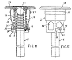
- FIGS. 11 and 12 show an embodiment, the inside pressure spring 32 being inside the riser pipe, namely the upper riser pipe part 10 with a larger diameter is arranged that it is supported on the one hand on the inner surface of the conical extension 9 and on the other hand on the sealing ball 31.
- the housing 33 is formed in one piece with a head plate 34.
- a bayonet catch at the lower end of the housing 33 35 is provided between the housing and the base plate 14.
- angular recesses 38 are provided on the circumference at the lower edge of the housing 33, so that the base plate 14 forms the said bayonet catch 35 with outwardly projecting projections.
- the housing 36 has through openings 36.
- the external screw thread 37 is attached to the housing.
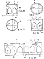
- FIGS. 13 to 16 illustrate a simplified and lighter design of a base plate 39, which consists of an annular disk 40 with three integrally molded guide webs 41, 42 and 43 directed upward on the inner edge, with at least one point on the circumference of the annular disk 40 again trapezoidal depression 44 corresponding to the depression 29 according to FIGS. 5 to 8 is provided.
Abstract
Description
Die Erfindung bezieht sich auf eine Sicherheitsvorrichtung für einen Ventileinsatz in einer Auslauföffnung eines unter Druck stehenden Getränkefasses, insbesondere Bierfasses, mit einem Gehäuse, einem Steigrohr, einer Bodenplatte, einer Außendruckfeder, welche sich einerseits an der Bodenplatte und andererseits an einem Dichtungskörper abstützt, und mit mindestens einem Verriegelungselement, welches derart schwenkbar zwischen der Außendruckfeder und der Bodenplatte eingespannt ist, daß es beim axial gerichteten Einsatzvorgang gegenüber der Faß-Auslaßöffnung ausweicht und in Betriebsstellung hinter deren inneren Rand greift.The invention relates to a safety device for a valve insert in an outlet opening of a pressurized beverage keg, in particular a beer keg, with a housing, a riser pipe, a base plate, an external compression spring, which is supported on the one hand on the base plate and on the other hand on a sealing body, and with at least one locking element which is pivotally clamped between the external compression spring and the base plate in such a way that it evades the barrel outlet opening in the axially directed operation and engages behind its inner edge in the operating position.
Sicherheitsvorrichtungen der vorgenannten Art sind in der Praxis in verschiedenen Ausführungen bekannt. Sie dienen dazu, ein unter Druck stehendes Getränkefaß, insbesondere ein Bierfaß, nach dem Füllen und während des Transportes an der Auslaßöffnung abzudichten und beim späteren Abfüllen des Getränkes mit einem Zapfkopf verbunden zu werden. Bei der fabrikmäßigen Vorbereitung der Getränkefässer werden die Sicherheitsvorrichtungen in die jeweilige Auslaßöffnung des Getränkefasses eingesetzt. Der hier einfach als Faß-Auslaßöffnung bezeichnete Teil des Getränkefasses besitzt im allgemeinen einen Rohrstutzen, der mindestens zum Teil in das Getränkefaß hineinragt und nach dem äußeren oberen Ende zu mit einem Innengewinde versehen ist, so daß die Sicherheitsvorrichtung, die mit einem entsprechenden Außengewinde versehen ist, nach dem Einsatz festgeschraubt werden kann. Sodann wird das Getränkefaß weiteren Behandlungsvorgängen unterworfen, insbesondere Druckmessung auf Dichtigkeit, Reinigung usw. bis letztlich das Getränkefaß an einer anderen Stelle, nämlich an einer separaten Einlaßöffnung mit dem Getränke gefüllt und sodann verschlossen wird.Various types of safety devices of the aforementioned type are known in practice. They serve to seal a pressurized beverage keg, in particular a beer keg, after filling and during transport at the outlet opening and to be connected to a dispensing head when the beverage is subsequently filled. During the factory preparation of the beverage kegs, the safety devices are inserted into the respective outlet opening of the beverage keg. The part of the beverage keg simply referred to here as the barrel outlet opening generally has a pipe socket which at least partially projects into the beverage keg and is provided with an internal thread towards the outer upper end, so that the safety device, which is provided with a corresponding external thread , can be screwed tight after use. The beverage keg is then subjected to further treatment processes, in particular pressure measurement for leaks, cleaning, etc. until finally the beverage keg at another location, namely at a separate inlet opening with which drinks are filled and then closed.
In der Praxis haben sich zahlreiche Unfälle ereignet, und zwar meist durch unsachgemäße Behandlung des Ventileinsatzes in der Faß-Auslaßöffnung. Wenn man nämlich die bisher allgemein üblichen Ventileinsätze bei gefülltem oder zumindest teilweise gefülltem Getränkefaß herausgeschraubt hat, so hat der Innendruck im Getränkefaß bewirkt, daß die gesamte Vorrichtung unter hoher Geschwindigkeit nach oben hin wegfliegt und dabei eine große Gefahr für die bedienende Person darstellt.In practice, numerous accidents have occurred, mostly due to improper handling of the valve insert in the barrel outlet opening. If you have unscrewed the previously common valve inserts when the beverage keg is full or at least partially full, the internal pressure in the beverage keg has caused the entire device to fly upwards at high speed and pose a great danger to the operator.
Um dieser Gefahr vorzubeugen, wurden allgemein gültige Vorschriften erlassen, die Ventileinsätze mit Sicherheitsvorrichtungen zu versehen, die auf jeden Fall verhindern sollen, daß bei unsachgemäßem Bedienen der Ventileinsatz herausfliegen kann. Die Folge dieser Vorschriften war, daß die verschiedensten, meist sehr komplizierte Konstruktionen bekanntgeworden sind. So ist aus der Praxis eine Sicherheitsvorrichtung bekannt, die im Einsatz eine Bajonettplatte aufweist, an welcher ein feststehender Haken vorgesehen ist, der in Betriebsstellung unter den unteren bzw. inneren Rand eines Rohrstutzens an der Faß-Auslaßöffnung greift. Diese Konstruktion hat aber den Nachteil, daß die gesamte Sicherheitvorrichtung mit ihren Einzelteilen in demontiertem Zustand eingesetzt werden muß, weil die Abmessungen der Bajonettplatte wegen des feststehenden Hakens größer als der Durchmesser der Faß-Auslaßöffnung bzw. des besagten Rohrstutzens ist. Die Bajonettplatte muß daher zunächst allein in Schrägstellung durch die Auslaßöffnung auf die Innenseite des Rohrstutzens gebracht und anschließend in die richtige Lage geschwenkt werden, wonach dann der eigentliche Zusammenbau der Sicherheitsvorrichtung unter Einrasten des Bajonettverschlusses usw. erfolgen muß. Bei der serienmäßigen Behandlung der Getränkefässer in der Getränkeindustrie sind diesem Manipulationen in Anbetracht der großen Anzahl der anfallenden Fässer außerordentlich umständlich und zeitraubend.In order to prevent this danger, generally applicable regulations have been issued to provide the valve inserts with safety devices which are to prevent the valve insert from flying out if operated improperly. The consequence of these regulations was that the most varied, mostly very complicated constructions became known. For example, a safety device is known in practice which has a bayonet plate in use, on which a fixed hook is provided which, in the operating position, engages under the lower or inner edge of a pipe socket at the barrel outlet opening. However, this construction has the disadvantage that the entire safety device with its individual parts must be used in the disassembled state because the dimensions of the bayonet plate are larger than the diameter of the barrel outlet opening or the said pipe socket because of the fixed hook. The bayonet plate must therefore first be brought into an inclined position through the outlet opening on the inside of the pipe socket and then pivoted into the correct position, after which the actual assembly of the safety device must take place with the bayonet catch, etc. In the standard treatment of beverage barrels in the beverage industry, manipulations are considered the large number of barrels produced is extremely cumbersome and time-consuming.
Eine ähnliche zu Anfang angegebene Sicherheitsvorrichtung ist aus der GB-OS 21 88 040 bekannt. Auch hier ist das eigentliche Verriegelungselement in Form eines radial nach außen ragenden Hakens einstückig an der Bajonettplatte angeformt. Aus diesem Grunde kann zunächst nur eine Teilmontage der Sicherheitsvorrichtung vorgenommen werden, nämlich eine Teilmontage des Zentralrohres mit Dichtungskranz, Druckfeder und zunächst loser Bajonettplatte. Wegen des radialen Vorsprunges des Verriegelungselementes kann das Einführen durch die Auslaßöffnung des Fasses nur in Schrägstellung der Bajonettplatte und des Zentralrohres erfolgen. Danach erfolgt der endgültige Zusammenbau der Sicherheitsvorrichtung durch Aufsetzen eines separaten Kopfteiles mit einem zylindrischen Rohrstutzen, an dessen inneren Ende L-förmige Schlitze vorgesehen sind, in welche radiale Vorsprünge der Bajonettplatte zum Einsatz gebracht werden müssen. Erst danach kann das endgültige Einschrauben der Sicherheitsvorrichtung in die Auslaßöffnung des Fasses erfolgen. Auch hier sind die Montagevorgänge recht umständlich und zeitraubend, zumal die Druckfeder bei der Montage am Faß zusammengedrückt werden muß, um die Bajonettplatte zum Einrasten zu bringen.A similar safety device specified at the beginning is known from GB-OS 21 88 040. Here too, the actual locking element is integrally formed on the bayonet plate in the form of a radially projecting hook. For this reason, only a partial assembly of the safety device can be carried out, namely a partial assembly of the central tube with a sealing ring, compression spring and initially a loose bayonet plate. Because of the radial projection of the locking element, the insertion through the outlet opening of the barrel can only take place in the inclined position of the bayonet plate and the central tube. Then the final assembly of the safety device takes place by placing a separate head part with a cylindrical pipe socket, at the inner end of which L-shaped slots are provided, into which radial projections of the bayonet plate must be used. Only then can the safety device be finally screwed into the outlet opening of the drum. Here, too, the assembly processes are quite cumbersome and time-consuming, especially since the compression spring has to be compressed during assembly on the barrel in order to snap the bayonet plate into place.
Eine weitere ähnlich aufgebaute Sicherheitsvorrichtung ist aus der WO 91/026 94-A1 bekannt. Bei dieser Konstruktion besteht das Verriegelungselement aus einer verhältnismäßig langen sich axial erstreckenden Zunge, an deren oberen Ende ein Ring angeformt ist, der seinerseits von dem oberen Ende der Druckfeder gehalten ist. Das untere Ende der Zunge ist nach außen umgebogen und weist einen radial nach außen gerichteten Steg auf. Wegen dieser Formgestaltung des Verriegelungselementes muß auch hier die Montage zunächst in einer Schrägstellung des Zentralrohres und der umgebenden Teile erfolgen, bevor das Gehäuse gerade gerichtet, axial eingeschoben und schließlich festgeschraubt werden kann.Another similarly constructed safety device is known from WO 91/026 94-A1. In this construction, the locking element consists of a relatively long, axially extending tongue, at the upper end of which a ring is formed, which in turn is held by the upper end of the compression spring. The lower end of the tongue is bent outwards and has a radially outward web. Because of this shape of the locking element, the assembly must also first in an inclined position of the central tube and the surrounding Parts take place before the housing can be straightened, inserted axially and finally screwed down.
Schließlich ist noch aus der DE-OS 38 44 428 eine aufbruchsichere Verankerung für Zapfrohre an Bierbehältern bekannt. Hierbei sind an einem oberen Verschlußstück drei auf dem Umfang verteilte achsparallel verlaufende Stäbe vorgesehen, an deren unterem Ende mittels Gelenken od. dgl. schräg nach oben und außen führende abgewinkelte Arme angelenkt sind, welche durch Fenster in der Rohrwand des Kopfstückes greifen. Die freien Enden dieser Arme sind auf die Innenfläche des Gefäßhalses gerichtet, so daß ein Lösen des Kopfstückes vom Faß durch Drehen verhindert wird.Finally, from DE-OS 38 44 428 a break-proof anchoring for dispensing pipes on beer containers is known. Here, on an upper closure piece, three axially parallel rods distributed over the circumference are provided, at the lower end of which are articulated by means of joints or the like. Angled arms leading obliquely upwards and outwards, which engage through windows in the tube wall of the head piece. The free ends of these arms are directed towards the inner surface of the neck of the vessel, so that loosening of the head piece from the barrel is prevented by turning.
Weitere Sicherheitsvorrichtungen sind aus der GB-A-2 209 740 sowie der US-A-1 003 447 bekannt.Further safety devices are known from GB-A-2 209 740 and US-A-1 003 447.
Eine zu Anfang angegebene Sicherheitsvorrichtung ist aus der DE-A-41 14 604 bekannt. Es ergibt sich hier zwar eine konstruktiv einfache, zusammensetzbare und einsetzbare Vorrichtung, jedoch hat sich herausgestellt, daß vor allem der Ausbau aus der Faß-Auslaßöffnung für die Praxis zu umständlich und zeitaufwendig ist.A safety device specified at the beginning is known from DE-A-41 14 604. Although this results in a structurally simple, assemblable and usable device, it has been found that, above all, the removal from the barrel outlet opening is too cumbersome and time-consuming for practice.
Demgegenüber liegt der Erfindung die Aufgabe zu Grunde, eine Sicherheitsvorrichtung zu schaffen, die einerseits im vollständig zusammengebauten Zustand durch einfaches axiales Eindrücken in die Faß-Auslaßöffnung und durch anschließendes Festschrauben in Betriebsstellung gebracht werden kann und die andererseits durch Verwendung eines Sonderzapfkopfes wieder als geschlossene Einheit ausgebaut werden kann.In contrast, the invention has for its object to provide a safety device that can be brought into the operating position on the one hand in the fully assembled state by simply axially pressing into the barrel outlet opening and by subsequent screwing and on the other hand expanded again as a closed unit by using a special tap head can be.
Die gestellte Aufgabe wird erfindungsgemäß dadurch gelöst, daß das Verriegelungselement als Doppelwinkelstück mit einem nach außen ragenden Steg, einem Schrägteil und einem inneren Vorsprung ausgebildet ist, daß der Steg in einer trapezartigen Vertiefung der Bodenplatte gelagert ist, daß das Steigrohr eine konische Erweiterung zwischen dem unteren Steigrohrteil mit kleinem Durchmesser und dem oberen im Gehäuse befindlichen Steigrohrteil mit größerem Durchmesser aufweist und daß die konische Erweiterung mit einem Abstand von dem Vorsprung des Verriegelungselementes vorgesehen ist, der größer als der normale Öffnungshub des Steigrohres ist.The object is achieved in that the locking element is designed as a double angle piece with an outwardly projecting web, an inclined part and an inner projection that the web in one trapezoidal recess of the base plate is mounted that the riser has a conical extension between the lower riser part with a small diameter and the upper riser part located in the housing with a larger diameter and that the conical extension is provided at a distance from the projection of the locking element which is greater than is the normal opening stroke of the riser pipe.
Auf diese Weise ergibt sich der wesentliche Vorteil, daß bei normaler Bedienung des Ventileinsatzes mit der Sicherheitsvorrichtung mittels eines normalen Zapfkopfes die volle Sicherheit erhalten bleibt, auch bei unsachgemäßer Behandlung, daß aber der Ausbau mittels eines Sonderzapfkopfes sehr schnell und in einfacher Weise erfolgen kann. Ein derartiger Sonderzapfkopf, der einen wesentlich größeren Hub des Steigrohres erzeugt als ein normaler Zapfkopf, ist nur im Herstellerwerk bzw. in den Abfüllstationen verfügbar, nicht aber auf dem freien Markt erhältlich.In this way, there is the essential advantage that with normal operation of the valve insert with the safety device by means of a normal dispensing head, full safety is maintained, even in the event of improper handling, but that the removal can be carried out very quickly and easily using a special dispensing head. Such a special dispensing head, which produces a much greater stroke of the riser pipe than a normal dispensing head, is only available in the manufacturer's plant or in the filling stations, but is not available on the open market.
Vorteilhafte Ausgestaltungen der Erfindung ergeben sich aus den Unteransprüchen.Advantageous refinements of the invention result from the subclaims.
In der Zeichnung sind Ausführungsbeispiele der Erfindung im Schema dargestellt, und zwar zeigen:
- Fig. 1 einen mittleren Vertikalschnitt durch eine Sicherheitsvorrichtung,
- Fig. 2 einen Vertikalschnitt durch ein Bajonettrohr,
- Fig. 3 eine perspektivische Ansicht eines Verriegelungselementes in vergrößerter Darstellung,
- Fig. 4 einen Vertikalschnitt durch eine Zentrierscheibe in vergrößerter Darstellung,
- Fig. 5 einen Vertikalschnitt durch eine Bodenplatte,
- Fig. 6 eine Draufsicht auf die Bodenplatte gemäß Fig. 5,
- Fig. 7 einen Schnitt gemäß Schnittlinie VII-VII in Fig. 6,
- Fig. 8 eine Seitenansicht zu Fig. 6,
- Fig. 9 einen mittleren Vertikalschnitt durch eine Sicherheitsvorrichtung in einer anderen Ausgestaltung,
- Fig. 10 ein Bajonettrohr entsprechend Fig. 2, welches in der Sicherheitsvorrichtung gemäß Fig. 9 Verwendung findet,
- Fig. 11 einen mittleren Vertikalschnitt durch eine Sicherheitsvorrichtung in einer anderen Ausgestaltung,
- Fig. 12 eine Vorderansicht zu Fig. 11,
- Fig. 13 einen Vertikalschnitt durch eine Bodenplatte in einer anderen Ausgestaltung,
- Fig. 14 eine Draufsicht zu Fig. 13,
- Fig. 15 einen Schnitt gemäß Schnittlinie XV-XV in Fig. 14,
- Fig. 16 einen mittleren Vertikalschnitt zu Fig. 14,
- Fig. 17 eine Seitenansicht auf das Bajonettrohr entsprechend Fig. 2,
- Fig. 18 eine Ansicht auf die Unterseite des Bajonettrohres gemäß Fig. 17,
- Fig. 19 eine Draufsicht zu Fig. 17,
- Fig. 20 einen mittleren Vertikalschnitt zu Fig. 17 und
- Fig. 21 eine Abwicklung des Bajonettrohres gemäß Fig. 17.
- 1 is a middle vertical section through a safety device,
- 2 shows a vertical section through a bayonet tube,
- 3 is a perspective view of a locking element in an enlarged view,
- 4 shows a vertical section through a centering disk in an enlarged view,
- 5 shows a vertical section through a base plate,
- 6 shows a plan view of the base plate according to FIG. 5,
- 7 shows a section along section line VII-VII in FIG. 6,
- 8 is a side view of FIG. 6,
- 9 is a middle vertical section through a safety device in another embodiment,
- 10 shows a bayonet tube corresponding to FIG. 2, which is used in the safety device according to FIG. 9,
- 11 is a middle vertical section through a safety device in another embodiment,
- 12 is a front view of FIG. 11,
- 13 shows a vertical section through a base plate in another embodiment,
- 14 is a plan view of FIG. 13,
- 15 shows a section along section line XV-XV in FIG. 14,
- 16 is a middle vertical section of FIG. 14,
- 17 is a side view of the bayonet tube corresponding to FIG. 2,
- 18 is a view of the underside of the bayonet tube according to FIG. 17,
- 19 is a plan view of FIG. 17,
- Fig. 20 is a middle vertical section to Fig. 17 and
- 21 shows a development of the bayonet tube according to FIG. 17.
Die Fig. 1 bis 8 veranschaulichen ein Ausführungsbeispiel einer Sicherheitsvorrichtung für den Einsatz in eine Faß-Auslaßöffnung eines unter Druck stehenden Getränkefasses, insbesondere Bierfasses. Von der an sich bekannten Faß-Auslaßöffnung ist in Fig. 1 nur der besseren Veranschaulichung wegen ein Teil eines Rohrstutzens 45 mit einem unteren Rand 46 im Vertikalschnitt dargestellt. Die Einsatzvorrichtung 1, die in der Fachsprache auch Fitting genannt wird, weist ein Gehäuse auf, welches aus einem Nockenring 2 und einem Bajonettrohr 7 gebildet ist. Der Nockenring besitzt ein Außengewinde 3 und auf dem inneren Umfang nahe dem unteren Ende drei gleichmäßig verteilte Nocken 4, die mit dem oberen Ende des Bajonettrohres einen Bajonettverschluß bilden. Zu diesem Zweck sind am oberen Rande des Bajonettrohres 7 entsprechend drei auf dem Umfang verteilte Ausnehmungen 16 und waagerechte Laschen 17 mit je einem Rastkopf 18 vorgesehen. Im Bereich des Nockenringes befindet sich ein Dichtkörper 5 sowie eine Dichtungsplatte 6. Zentral in dem Gehäuse befindet sich ein Steigrohr 8, welches mit dem unteren Ende bis zu einem gewissen Abstand vom Boden des Getränkefasses reicht. Am oberen Ende weist das Steigrohr einen nach außen umgebördelten Rand auf, welcher zwischen dem Dichtkörper 5 und dem oberen Ende einer Außendruckfeder 13 gehalten ist.1 to 8 illustrate an embodiment of a safety device for use in a barrel outlet opening of a pressurized beverage barrel, in particular a beer barrel. Of the barrel outlet opening known per se, part of a
Das Steigrohr 8 ist mit einer konischen Erweiterung 9 versehen, so daß das untere Steigrohrteil einen kleineren Durchmesser und das obere in den Gehäuseteilen 3 und 7 befindliche Steigrohrteil 10 einen größeren Durchmesser aufweisen. Innerhalb des Steigrohres befindet sich eine Innendruckfeder 11, welche sich bei diesem Ausführungsbeispiel gemäß Fig. 1 mit dem unteren Ende an einer umlaufenden Sicke 12 im Steigrohr und mit dem oberen Ende an der Unterseite der Dichtungsplatte 6 abstützt.The
Das Bajonettrohr 7 weist am unteren Bereich bzw. nach dem inneren Ende zu drei auf dem Umfang verteilte radiale Einwölbungen 21 auf, auf deren oberen Rändern eine Bodenplatte 14 aufliegt, die gleichzeitig innerhalb des Bajonettrohres 7 zentriert wird. Wie insbesondere die Fig. 5 bis 8 veranschaulichen, besteht die Bodenplatte aus einer Ringscheibe 27 und einem einstückig angeformten Führungskragen 28. Dieser Führungskragen umgibt das untere Ende des oberen im Durchmesser vergrößerten Steigrohrteiles 10. Die Ringscheibe 27 der Bodenplatte ist mit einer trapezartigen Vertiefung 29 versehen. Außerdem weist der Führungskragen 28 der Bodenplatte im Bereich der trapezartigen Vertiefung 29 eine Durchtrittsöffnung 30 für ein Verriegelungselement 15 auf.The
Das Verriegelungselement 15 ist, wie die vergrößerte perspektivische Darstellung gemäß Fig. 3 zeigt, als Doppelwinkelstück mit einem nach außen ragenden Steg 22, einem Schrägteil 23 und einem inneren Vorsprung 24 ausgebildet. Der Steg 22 des Verriegelungselementes 15 ist in der trapezartigen Vertiefung 29 der Bodenplatte 14 gelagert und gleichzeitig seitlich gesichert und geführt. Die Höhe der Vertiefung 29 entspricht der Höhe bzw. Dicke des Steges 22 des Verriegelungselementes, so daß die letzte untere Bindung der Außendruckfeder 13 auf dem gesamten Umfang dicht auf der Bodenplatte 14 und dem Verriegelungselement 15 aufliegt, so daß der Druck der Außendruckfeder das Verriegelungselement 19 in die auswärts geschwenkte Betriebsstellung bzw. Verriegelungsstellung gegenüber dem unteren Rand 46 des Faß-Auslaßstutzens 45 hält.The locking
Die konische Erweiterung 9 am Steigrohr 8 ist bezogen auf die Verschlußstellung des Ventileinsatzes mit einem Abstand von der oberen Fläche des Vorsprunges 24 des Verriegelungselementes 15 vorgesehen, der größer als der normale Öffnungshub des Steigrohres 8 ist.The
Auf Grund dieser besonderen Konstruktion ergibt sich folgende Wirkungsweise.This special construction results in the following mode of operation.
Wenn die Sicherheitsvorrichtung in der Faß-Auslaßöffnung eingebaut wird, so befindet sich das Verriegelungselement 15 durch Druck der Außendruckfeder 13 ständig in Verriegelungsstellung. Außerdem ist der Ventileinsatz am oberen Ende abgedichtet. Wenn nun zum Abzapfen des Getränkes ein üblicher Zapfkopf aufgesetzt und betätigt wird, so wird der Dichtkörper 5 mit der Dichtungsplatte 6 und das Steigrohr 8, 10 entgegen dem Druck der Außendruckfeder 13 nach unten gedrückt. Der von dem normalen Zapfkopf erzeugte Hub ist jedoch kleiner als der Abstand der konischen Erweiterung 9 von dem Vorsprung 24 des Verriegelungselementes 15, so daß die obere Innenkante des Vorsprunges 24 allenfalls in Berührung mit dem inneren Rand der konischen Erweiterung 9 kommt. Wenn stattdessen ein Sonderzapfkopf aufgesetzt wird, wird durch diesen ein so großer Hub erzeugt, daß die konische Erweiterung 9 auf den Vorsprung 24 trifft, so daß die innere obere Kante des Vorsprunges 24 unter gleichzeitiger Schwenkbewegung des Verriegelungselementes 15 an der konischen Erweiterung 9 entlanggleitet bis hin zu dem unteren Bereich des oberen Steigrohrteiles 10. Damit wird das Verriegelungselement 15 gezwungen, in der Darstellung gemäß Fig. 1 entgegen dem Uhrzeigersinn so weit nach innen einzuschwenken, daß die Außenkante des Verriegelungselementes 15 sich innerhalb der Faß-Auslaßöffnung befindet, so daß man nun die Sicherheitsvorrichtung insgesamt in einfacher Weise herausschrauben kann.When the safety device is installed in the barrel outlet opening, the locking
Bei der beschriebenen Sicherheitsvorrichtung genügt es im allgemeinen, nur ein einziges Verriegelungselement 15 in der beschriebenen Weise vorzusehen. Zur Vergrößerung der Sicherheit können aber auch mehrere, vorzugsweise drei Verriegelungselemente auf dem Umfang mit gleichmäßigen Abständen und in entsprechenden trapezartigen Vertiefungen angeordnet werden.In the described safety device, it is generally sufficient to provide only a
Das Bajonettohr 7 ist auf dem Umfang mit mehreren Durchlaßöffnungen 19, 20 ausgestattet, die einmal beim Öffnen des Ventileinsatzes den Durchgang des von außen zugeführten Druckgases gestatten und die zum anderen zum Erleichtern der Reinigung der Vorrichtung dienen.The
Je nach Ausgestaltung der Sicherheitsvorrichtung kann eine zusätzliche Führung des Steigrohres 8 dadurch erreicht werden, daß eine Zentrierscheibe 25 mit einem Zentrierkranz 26 an geeigneter Stelle eingelegt wird, z. B. zwischen dem unteren Ende der Außendruckfeder 13 und der Bodenplatte 14.Depending on the design of the safety device, an additional guidance of the
Die nachfolgend erläuterten Fig. 9 bis 16 sollen veranschaulichen, daß die erfindungsgemäßen Maßnahmen auch bei anders ausgestalteten Sicherheitsvorrichtungen anwendbar sind. So zeigt Fig. 9 die an sich bekannte Verwendung einer Dichtungskugel 31 anstelle der Dichtungsplatte 6 gemäß Fig. 1. Die Fig. 11 und 12 zeigen eine Ausgestaltung, wobei innerhalb des Steigrohres, und zwar des oberen im Durchmesser vergrößerten Steigrohrteiles 10 die Innendruckfeder 32 derart angeordnet ist, daß sie sich einerseits an der Innenfläche der konischen Erweiterung 9 und andererseits an der Dichtungskugel 31 abstützt. Bei dieser Gestaltungsweise ist es vorteilhaft, daß die Innendruckfeder 32 zwischen der Innenfläche der konischen Erweiterung 9 und der Dichtungskugel 31 nach oben hin konisch verjüngt ist. Zum Unterschied gegenüber der Ausführung nach Fig. 1 ist das Gehäuse 33 einstückig mit einer Kopfplatte 34 ausgebildet. Außerdem ist am unteren Ende des Gehäuses 33 ein Bajonettverschluß 35 zwischen dem Gehäuse und der Bodenplatte 14 vorgesehen. Zu diesem Zweck sind am unteren Rande des Gehäuses 33 winkelförmige Ausnehmungen 38 auf dem Umfang vorgesehen, so daß die Bodenplatte 14 mit nach außen ragenden Vorsprüngen den besagten Bajonettverschluß 35 bilden. Das Gehäuse 36 weist ähnlich wie das Bajonettrohr 7 Durchlaßöffnungen 36 auf. Ferner ist an dem Gehäuse das Außenschraubgewinde 37 angebracht.FIGS. 9 to 16 explained below are intended to illustrate that the measures according to the invention can also be used with differently designed safety devices. 9 shows the use of a sealing
Die Fig. 13 bis 16 veranschaulichen eine vereinfachte und leichtere Ausführung einer Bodenplatte 39, die aus einer Ringscheibe 40 mit drei am Innenrand nach oben gerichtete einstückig angeformten Führungsstegen 41, 42 und 43 besteht, wobei an mindestens einer Stelle des Umfanges der Ringscheibe 40 wieder eine trapezartige Vertiefung 44 entsprechend der Vertiefung 29 gemäß den Fig. 5 bis 8 vorgesehen ist.13 to 16 illustrate a simplified and lighter design of a
Claims (10)
- A safety device for a valve-inset in the dispensing aperture of a pressurized beverage cask, in particular a beer keg, comprising a housing (3, 7), a rise pipe (8), a base plate (14), an external compression spring (13) resting on one hand against the base plate (14) and on the other hand against a seal (5), further comprising at least one locking element (15) pivotably mounted in such manner between the external compression spring (13) and the base plate (14) that it moves out of the way relative to the cask dispensing aperture (45) during the axially directed insertion procedure and that it engages the inside rim (46) from behind,
characterized in that
the locking element (15) is designed as a double-angled piece with an outwardly projecting tang (22), an oblique segment (23) and an inward projection (24), in that the tang (22) rests in a trapezoidal recess (29) of the base plate (14), in that the rise pipe (8) comprises a conical flaring (9) between the lower rise-pipe portion of lesser diameter and the upper rise-pipe portion (10) of larger diameter and present in the housing (3, 7), and in that the conical flaring (9) is away from the projection (24) of the locking element (15) by a distance larger than the normal opening excursion of the rise pipe (8). - Safety device defined in claim 1, characterized in that the housing is composed of a pin-fitted ring (2) and a bayonet-fitted pipe (7) which cooperate in the manner of a mutual bayonet lock (4, 16, 17, 18).
- Safety device defined in claim 2, characterized in that the bayonet-fitted pipe (7) comprises circumferentially distributed, radial recesses (21) supporting the base plate (14) by their upper edges.
- Safety device defined in claim 3, characterized in that the base plate (14) consists of an annular pane (27) with an integral guide collar (28) and in that the guide collar (28) encloses the lower end of the upper rise-pipe portion (10).
- Safety device defined in claim 4, characterized in that the guide collar (28) comprises a transmission aperture (30) for the locking element (15) in the vicinity of the trapezoidal recess (29).
- Safety device defined in one of claims 2 through 5, characterized in that the bayonet-fitted pipe (7) comprises several circumferentially distributed transmission apertures (19, 20).
- Safety device defined in one of the above claims, characterized in that an internal compression spring (11, 32) is mounted inside the rise pipe (8, 10) and rests on one hand against the inside surface of the conical flaring (9) or against a circumferential constriction (12) and on the other hand against a sealing plate (6) or a sealing ball (31).
- Safety device defined in claim 7, characterized in that the internal compression spring (32) tapers conically upward between the inside surface of the conical flaring (9) and the sealing ball (31).
- Safety device defined in claim 1, characterized in that the base plate (39) is composed of an annular pane (40) with the trapezoidal recess (44) and of three integral guide tangs (41, 42, 43) at the inside edge.
- Safety device defined in one of the above claims, characterized in that a centering disk (25) with an integral centering collar (26) is inserted between the lower end of the external compression spring (13) and the base plate (14, 39).
Applications Claiming Priority (1)
| Application Number | Priority Date | Filing Date | Title |
|---|---|---|---|
| PCT/EP1993/000164 WO1994016985A1 (en) | 1993-01-25 | 1993-01-25 | Safety device for a valve insert in a beverage barrel |
Publications (2)
| Publication Number | Publication Date |
|---|---|
| EP0680453A1 EP0680453A1 (en) | 1995-11-08 |
| EP0680453B1 true EP0680453B1 (en) | 1996-06-19 |
Family
ID=8165702
Family Applications (1)
| Application Number | Title | Priority Date | Filing Date |
|---|---|---|---|
| EP93902247A Expired - Lifetime EP0680453B1 (en) | 1993-01-25 | 1993-01-25 | Safety device for a valve insert in a beverage barrel |
Country Status (13)
| Country | Link |
|---|---|
| US (1) | US5526965A (en) |
| EP (1) | EP0680453B1 (en) |
| JP (1) | JP3285869B2 (en) |
| AT (1) | ATE139512T1 (en) |
| AU (1) | AU3352393A (en) |
| BR (1) | BR9307775A (en) |
| CZ (1) | CZ281647B6 (en) |
| DE (1) | DE59303044D1 (en) |
| DK (1) | DK0680453T3 (en) |
| ES (1) | ES2090960T3 (en) |
| PL (1) | PL171457B1 (en) |
| RU (1) | RU2093455C1 (en) |
| WO (1) | WO1994016985A1 (en) |
Families Citing this family (11)
| Publication number | Priority date | Publication date | Assignee | Title |
|---|---|---|---|---|
| ES2142191B1 (en) * | 1996-03-27 | 2000-11-16 | Conesa De La Cruz Luis | INVIOLABILITY AND SAFETY SYSTEM FOR VALVES FOR BARRELS AND PRESSURE LIQUID CONTAINERS. |
| JP3725242B2 (en) * | 1996-04-12 | 2005-12-07 | サントリー株式会社 | Spear tube of beer barrel |
| GB9827570D0 (en) * | 1998-12-15 | 1999-02-10 | Cypherco Limited | Improvements in or relating to valves |
| NL1014952C2 (en) * | 2000-04-14 | 2001-10-16 | Dispense Systems Internat B V | Stop valve for a pressure container. |
| NL1018206C2 (en) * | 2001-06-01 | 2002-12-03 | Dispense Systems Internat B V | Valve for a container to be pressurized. |
| US6367660B1 (en) * | 2001-09-20 | 2002-04-09 | Chang Kung-Chien | Safety device for a double valve arrangement for beer keg |
| TWI350270B (en) * | 2005-04-19 | 2011-10-11 | Ecokeg Pty Ltd | Liquid storage and dispensing apparatus |
| DE102006061120B4 (en) * | 2006-12-22 | 2011-12-22 | Khs Gmbh | Keg |
| GB2485528B (en) * | 2010-11-09 | 2013-03-06 | Petainer Lidkoeping Ab | Keg closure with safety mechanism |
| GB2559394B (en) | 2017-02-03 | 2020-04-15 | Petainer Large Container Ip Ltd | Closure with venting system |
| WO2021211008A1 (en) * | 2020-04-14 | 2021-10-21 | Сергей Владимирович КНЯЗЕВ | Fitting for a pet keg |
Family Cites Families (8)
| Publication number | Priority date | Publication date | Assignee | Title |
|---|---|---|---|---|
| US3596810A (en) * | 1969-09-02 | 1971-08-03 | Perlick Co Inc The | Keg-tapping system |
| US4411287A (en) * | 1980-04-22 | 1983-10-25 | Alumasc Limited | Valve-type closure for containers |
| DK153780C (en) * | 1986-03-18 | 1989-01-09 | Micro Matic As | VALVE, ISAIR FOR A PRESSURE CONTAINER, AND PROCEDURE FOR INSTALLING THE VALVE IN THE PRESSURE CONTAINER |
| US4736926A (en) * | 1986-11-07 | 1988-04-12 | Draft Systems, Inc. | Valve assembly and coupler therefor |
| DK418289A (en) * | 1989-08-24 | 1991-02-25 | Micro Matic As | ANTI-LASHING SECURITY SYSTEM |
| EP0493976A1 (en) * | 1990-12-27 | 1992-07-08 | Universal Equipment Co (London) Ltd | Safety device for a keg valve assembly |
| DE4114604C2 (en) * | 1991-05-04 | 1994-10-13 | Breitwisch Josef & Co | Safety device for beverage keg |
| DE4204660C2 (en) * | 1992-02-17 | 1994-09-15 | Hiwi Schankanlagen Gmbh | Device for removing liquids under pressure from a compressed gas from a container |
-
1993
- 1993-01-25 JP JP51658694A patent/JP3285869B2/en not_active Expired - Fee Related
- 1993-01-25 DE DE59303044T patent/DE59303044D1/en not_active Expired - Fee Related
- 1993-01-25 AT AT93902247T patent/ATE139512T1/en not_active IP Right Cessation
- 1993-01-25 US US08/495,399 patent/US5526965A/en not_active Expired - Fee Related
- 1993-01-25 CZ CZ951856A patent/CZ281647B6/en not_active IP Right Cessation
- 1993-01-25 AU AU33523/93A patent/AU3352393A/en not_active Abandoned
- 1993-01-25 RU RU9395117114A patent/RU2093455C1/en not_active IP Right Cessation
- 1993-01-25 BR BR9307775A patent/BR9307775A/en not_active Application Discontinuation
- 1993-01-25 DK DK93902247.1T patent/DK0680453T3/en active
- 1993-01-25 EP EP93902247A patent/EP0680453B1/en not_active Expired - Lifetime
- 1993-01-25 PL PL93309984A patent/PL171457B1/en unknown
- 1993-01-25 WO PCT/EP1993/000164 patent/WO1994016985A1/en active IP Right Grant
- 1993-01-25 ES ES93902247T patent/ES2090960T3/en not_active Expired - Lifetime
Also Published As
| Publication number | Publication date |
|---|---|
| EP0680453A1 (en) | 1995-11-08 |
| ES2090960T3 (en) | 1996-10-16 |
| PL171457B1 (en) | 1997-04-30 |
| JP3285869B2 (en) | 2002-05-27 |
| JPH08505590A (en) | 1996-06-18 |
| BR9307775A (en) | 1995-10-31 |
| AU3352393A (en) | 1994-08-15 |
| RU2093455C1 (en) | 1997-10-20 |
| CZ281647B6 (en) | 1996-11-13 |
| DE59303044D1 (en) | 1996-07-25 |
| DK0680453T3 (en) | 1996-11-25 |
| ATE139512T1 (en) | 1996-07-15 |
| PL309984A1 (en) | 1995-11-13 |
| WO1994016985A1 (en) | 1994-08-04 |
| CZ185695A3 (en) | 1996-04-17 |
| US5526965A (en) | 1996-06-18 |
Similar Documents
| Publication | Publication Date | Title |
|---|---|---|
| DE3000607C2 (en) | ||
| DE3018158C2 (en) | Compressed air fitting | |
| EP2720771B1 (en) | Liquid filter with an eccentric liquid discharge channel | |
| EP0680453B1 (en) | Safety device for a valve insert in a beverage barrel | |
| DE2800701A1 (en) | ARRANGEMENT FOR FASTENING A DEVICE ON A PRESSURIZED CARTRIDGE | |
| WO1990008729A1 (en) | Tap head for keg fittings | |
| DE2857757C2 (en) | ||
| EP0153677B1 (en) | Automatic closing device for a fuel tank | |
| DE3337060A1 (en) | CAP FOR A SECURITY CONTAINER | |
| EP0512152B1 (en) | Safety device for beverage cask | |
| AT398299B (en) | CASTING INSERT | |
| DE2949223C2 (en) | ||
| EP0301054B1 (en) | Screw closure for a bottle or similar | |
| EP0054717A1 (en) | Arrangement for delivering gas | |
| DE3844428C2 (en) | ||
| DE3418530A1 (en) | DEVICE FOR PLUGGING CONTAINERS WITH A NECK | |
| DE3518000C2 (en) | Beer tap | |
| DE3306626A1 (en) | STEEL BOTTLE FOR A BEVERAGE UNIT | |
| AT337031B (en) | VALVE MECHANISM | |
| DE1532424C3 (en) | Closure for containers such as bottles and the like | |
| DE2632734C2 (en) | Cones drinkers for animals | |
| DE3703115C2 (en) | ||
| DE4204660C2 (en) | Device for removing liquids under pressure from a compressed gas from a container | |
| DE4209130C2 (en) | Dosing cap | |
| EP0684778A1 (en) | Vacuum bottle |
Legal Events
| Date | Code | Title | Description |
|---|---|---|---|
| PUAI | Public reference made under article 153(3) epc to a published international application that has entered the european phase |
Free format text: ORIGINAL CODE: 0009012 |
|
| 17P | Request for examination filed |
Effective date: 19950821 |
|
| AK | Designated contracting states |
Kind code of ref document: A1 Designated state(s): AT BE DE DK ES FR GB IT NL |
|
| GRAH | Despatch of communication of intention to grant a patent |
Free format text: ORIGINAL CODE: EPIDOS IGRA |
|
| 17Q | First examination report despatched |
Effective date: 19951204 |
|
| GRAH | Despatch of communication of intention to grant a patent |
Free format text: ORIGINAL CODE: EPIDOS IGRA |
|
| GRAA | (expected) grant |
Free format text: ORIGINAL CODE: 0009210 |
|
| RAP1 | Party data changed (applicant data changed or rights of an application transferred) |
Owner name: D.S.I. GETRAENKEARMATUREN GMBH & CO. KG |
|
| AK | Designated contracting states |
Kind code of ref document: B1 Designated state(s): AT BE DE DK ES FR GB IT NL |
|
| REF | Corresponds to: |
Ref document number: 139512 Country of ref document: AT Date of ref document: 19960715 Kind code of ref document: T |
|
| REF | Corresponds to: |
Ref document number: 59303044 Country of ref document: DE Date of ref document: 19960725 |
|
| ITF | It: translation for a ep patent filed |
Owner name: STUDIO JAUMANN |
|
| GBT | Gb: translation of ep patent filed (gb section 77(6)(a)/1977) |
Effective date: 19960912 |
|
| ET | Fr: translation filed | ||
| REG | Reference to a national code |
Ref country code: ES Ref legal event code: FG2A Ref document number: 2090960 Country of ref document: ES Kind code of ref document: T3 |
|
| REG | Reference to a national code |
Ref country code: ES Ref legal event code: FG2A Ref document number: 2090960 Country of ref document: ES Kind code of ref document: T3 |
|
| REG | Reference to a national code |
Ref country code: DK Ref legal event code: T3 |
|
| PLBE | No opposition filed within time limit |
Free format text: ORIGINAL CODE: 0009261 |
|
| STAA | Information on the status of an ep patent application or granted ep patent |
Free format text: STATUS: NO OPPOSITION FILED WITHIN TIME LIMIT |
|
| 26N | No opposition filed | ||
| PGFP | Annual fee paid to national office [announced via postgrant information from national office to epo] |
Ref country code: DK Payment date: 20000120 Year of fee payment: 8 |
|
| PG25 | Lapsed in a contracting state [announced via postgrant information from national office to epo] |
Ref country code: DK Free format text: LAPSE BECAUSE OF NON-PAYMENT OF DUE FEES Effective date: 20010125 |
|
| REG | Reference to a national code |
Ref country code: DK Ref legal event code: EBP |
|
| REG | Reference to a national code |
Ref country code: GB Ref legal event code: IF02 |
|
| PGFP | Annual fee paid to national office [announced via postgrant information from national office to epo] |
Ref country code: ES Payment date: 20080130 Year of fee payment: 16 |
|
| PGFP | Annual fee paid to national office [announced via postgrant information from national office to epo] |
Ref country code: NL Payment date: 20080115 Year of fee payment: 16 Ref country code: IT Payment date: 20080125 Year of fee payment: 16 Ref country code: GB Payment date: 20080124 Year of fee payment: 16 Ref country code: DE Payment date: 20071204 Year of fee payment: 16 |
|
| PGFP | Annual fee paid to national office [announced via postgrant information from national office to epo] |
Ref country code: AT Payment date: 20080116 Year of fee payment: 16 |
|
| PGFP | Annual fee paid to national office [announced via postgrant information from national office to epo] |
Ref country code: FR Payment date: 20080111 Year of fee payment: 16 |
|
| PGFP | Annual fee paid to national office [announced via postgrant information from national office to epo] |
Ref country code: BE Payment date: 20080304 Year of fee payment: 16 |
|
| GBPC | Gb: european patent ceased through non-payment of renewal fee |
Effective date: 20090125 |
|
| NLV4 | Nl: lapsed or anulled due to non-payment of the annual fee |
Effective date: 20090801 |
|
| PG25 | Lapsed in a contracting state [announced via postgrant information from national office to epo] |
Ref country code: DE Free format text: LAPSE BECAUSE OF NON-PAYMENT OF DUE FEES Effective date: 20090801 Ref country code: AT Free format text: LAPSE BECAUSE OF NON-PAYMENT OF DUE FEES Effective date: 20090125 |
|
| REG | Reference to a national code |
Ref country code: FR Ref legal event code: ST Effective date: 20091030 |
|
| PG25 | Lapsed in a contracting state [announced via postgrant information from national office to epo] |
Ref country code: NL Free format text: LAPSE BECAUSE OF NON-PAYMENT OF DUE FEES Effective date: 20090801 Ref country code: GB Free format text: LAPSE BECAUSE OF NON-PAYMENT OF DUE FEES Effective date: 20090125 |
|
| PG25 | Lapsed in a contracting state [announced via postgrant information from national office to epo] |
Ref country code: BE Free format text: LAPSE BECAUSE OF NON-PAYMENT OF DUE FEES Effective date: 20090131 |
|
| REG | Reference to a national code |
Ref country code: ES Ref legal event code: FD2A Effective date: 20090126 |
|
| PG25 | Lapsed in a contracting state [announced via postgrant information from national office to epo] |
Ref country code: FR Free format text: LAPSE BECAUSE OF NON-PAYMENT OF DUE FEES Effective date: 20090202 Ref country code: ES Free format text: LAPSE BECAUSE OF NON-PAYMENT OF DUE FEES Effective date: 20090126 |
|
| PG25 | Lapsed in a contracting state [announced via postgrant information from national office to epo] |
Ref country code: IT Free format text: LAPSE BECAUSE OF NON-PAYMENT OF DUE FEES Effective date: 20090125 |