EP0680104A1 - Accumulateur avec canal de ventilation - Google Patents
Accumulateur avec canal de ventilation Download PDFInfo
- Publication number
- EP0680104A1 EP0680104A1 EP95106274A EP95106274A EP0680104A1 EP 0680104 A1 EP0680104 A1 EP 0680104A1 EP 95106274 A EP95106274 A EP 95106274A EP 95106274 A EP95106274 A EP 95106274A EP 0680104 A1 EP0680104 A1 EP 0680104A1
- Authority
- EP
- European Patent Office
- Prior art keywords
- channel
- porous body
- cover plate
- side channel
- degassing
- Prior art date
- Legal status (The legal status is an assumption and is not a legal conclusion. Google has not performed a legal analysis and makes no representation as to the accuracy of the status listed.)
- Granted
Links
Images

Classifications
-
- H—ELECTRICITY
- H01—ELECTRIC ELEMENTS
- H01M—PROCESSES OR MEANS, e.g. BATTERIES, FOR THE DIRECT CONVERSION OF CHEMICAL ENERGY INTO ELECTRICAL ENERGY
- H01M50/00—Constructional details or processes of manufacture of the non-active parts of electrochemical cells other than fuel cells, e.g. hybrid cells
- H01M50/30—Arrangements for facilitating escape of gases
- H01M50/383—Flame arresting or ignition-preventing means
-
- H—ELECTRICITY
- H01—ELECTRIC ELEMENTS
- H01M—PROCESSES OR MEANS, e.g. BATTERIES, FOR THE DIRECT CONVERSION OF CHEMICAL ENERGY INTO ELECTRICAL ENERGY
- H01M50/00—Constructional details or processes of manufacture of the non-active parts of electrochemical cells other than fuel cells, e.g. hybrid cells
- H01M50/30—Arrangements for facilitating escape of gases
- H01M50/35—Gas exhaust passages comprising elongated, tortuous or labyrinth-shaped exhaust passages
- H01M50/367—Internal gas exhaust passages forming part of the battery cover or case; Double cover vent systems
-
- H—ELECTRICITY
- H01—ELECTRIC ELEMENTS
- H01M—PROCESSES OR MEANS, e.g. BATTERIES, FOR THE DIRECT CONVERSION OF CHEMICAL ENERGY INTO ELECTRICAL ENERGY
- H01M50/00—Constructional details or processes of manufacture of the non-active parts of electrochemical cells other than fuel cells, e.g. hybrid cells
- H01M50/30—Arrangements for facilitating escape of gases
- H01M50/394—Gas-pervious parts or elements
-
- H—ELECTRICITY
- H01—ELECTRIC ELEMENTS
- H01M—PROCESSES OR MEANS, e.g. BATTERIES, FOR THE DIRECT CONVERSION OF CHEMICAL ENERGY INTO ELECTRICAL ENERGY
- H01M50/00—Constructional details or processes of manufacture of the non-active parts of electrochemical cells other than fuel cells, e.g. hybrid cells
- H01M50/30—Arrangements for facilitating escape of gases
- H01M50/308—Detachable arrangements, e.g. detachable vent plugs or plug systems
-
- Y—GENERAL TAGGING OF NEW TECHNOLOGICAL DEVELOPMENTS; GENERAL TAGGING OF CROSS-SECTIONAL TECHNOLOGIES SPANNING OVER SEVERAL SECTIONS OF THE IPC; TECHNICAL SUBJECTS COVERED BY FORMER USPC CROSS-REFERENCE ART COLLECTIONS [XRACs] AND DIGESTS
- Y02—TECHNOLOGIES OR APPLICATIONS FOR MITIGATION OR ADAPTATION AGAINST CLIMATE CHANGE
- Y02E—REDUCTION OF GREENHOUSE GAS [GHG] EMISSIONS, RELATED TO ENERGY GENERATION, TRANSMISSION OR DISTRIBUTION
- Y02E60/00—Enabling technologies; Technologies with a potential or indirect contribution to GHG emissions mitigation
- Y02E60/10—Energy storage using batteries
Definitions
- the invention relates to an accumulator containing an electrolytic liquid, such as sulfuric acid, according to the preamble of claim 1.
- the aim of the present invention is to improve the known accumulator and, in particular, to ensure that, even if the cover of the side channel becomes leaky, there is no risk of reignition and that acid mist cannot escape unhindered.
- the porous body Since the porous body is already arranged at the beginning of the side channel, there is no danger that an external flame will penetrate into the interior of the battery if there are any leaks between the cover plate and the battery cover.
- the acid mist is initially largely intercepted by the porous body, so that if the cover plate leaks, it at least does not larger volumes can escape to the outside.
- the porous body forms part of the battery cover after it has been installed, it does not need to be attached to the cover plate, so that it is not only much easier and more economical to manufacture, but also easy to handle and assemble.
- a flawless and space-saving mounting or accommodation of the porous body which preferably has the shape of a round disk, is achieved.
- a sharp deflection of the gas flow takes place within the gas passage gap, which promotes the separation of acid droplets from the escaping gas and thus prevents liquid from being transported to the outlet opening.
- claims 6 to 8 are advantageous both for the effectiveness of the acid mist separation and for simple manufacture and assembly.
- the side channel is divided into a part intended for the absorption of acid mist and the gas passage.
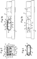
- FIG. 1 six screw plugs 34 are arranged one behind the other and at a defined distance along the long horizontal central axis 42 in the rectangular cover 11 of a battery 44 having poles 44, which are screwed tightly into a threaded bore 35 according to FIG. 2 and are arranged above the thread by means of one , in Figure 2 immediately below the lower end of the reference number "34" recognizable O-ring the interior 36 of an example Accumulator cell containing sulfuric acid closes tightly at the top.
- the threaded bores 35 are connected by straight-line degassing channels 12 extending along the horizontal central axis 42, which in turn are in flow connection with one another in that the screw plugs 34 according to FIG. 2 have a circumferential recess 38 above the screw thread 37, each having a diametrically opposite side Degassing duct 12 adjoins.
- the screw plugs 34 have a cavity 39 which is open at the bottom and which is connected to the interior 36 of the relevant battery cell and opens at the top into the circumferential recess 38 via a radial bore 40.
- baffles 41 are provided which force gases flowing from the interior 36 into the circumferential recess 38 to change flow direction several times in order to retain entrained liquid.
- the horizontal central axis 42 runs through the vertical central axes 43 of the screw plugs 34.
- a significantly shorter degassing duct 12 ′ extends from the two threaded bores 35 closest to the side walls 13 of the cover 11 to a funnel-like widening duct region 18 which is connected in the direction of the side walls 13 by a circumferential border 20 into which a circular disk-shaped porous body 17, for example a frit is inserted tightly.
- the two flat end surfaces of the porous body 17 are arranged vertically, so that gas flowing from the degassing channel 12 ′ into the funnel-shaped channel region 18 can flow from one end to the opposite end surface of the porous body 17.
- the casing 20 protrudes from the inner side wall 19 of two side channels 14 provided on opposite sides of the cover 11, which extend horizontally starting from the casing 20 in the direction away from the accumulator poles 44.
- the side channels 14 have an oval-like shape with an upper and lower horizontal straight section 26 and 27 arranged at a distance below them and two semicircular sections 28 and 29 arranged at their ends. This creates a flow path that is elongated in the horizontal direction for gases emerging from the interior of the accumulator.
- the side channel 14 initially has a constant depth, and finally in the area of the semicircular one Section 28 end to merge into a jump-like recess 45, which in turn has a constant depth. This creates a recessed wall part 19 '.
- the side channels 14 according to FIG. 3b are closed to the outside by a cover plate 15 shown from the inside in FIG. 4.
- the cover plate 15 has a shape which is complementary to the side channel 14 and to the adjacent border 20 and, according to FIGS. 2, 4, has an edge projecting towards the cover 11 with sealing means 32 projecting towards the cover 11.
- the edge 31 of the cover plate 15 engages in a step recess 30 which surrounds the edge of the side channel 14 facing the side wall 13 of the cover 11.
- the depth of the step recess 30 is selected so that the cover plate 15 placed on the side channel 14 is flush with the side wall 13.
- the cover plate 15 has a circular cylindrical depression 23 projecting towards the inside of the cover 11, in the bottom 24 of which a gas outlet opening 16 is provided and the bottom 24 of which extends into the recess 45
- Side wall 12 of the side channel 14 extends in and forms a narrow gas passage gap 25 with the recessed wall part 19 '.
- the degassing channel 12 opens out in relation to the upper half of the circular porous body 17, so that the funnel-shaped area is asymmetrical in the sense that the funnel walls form a substantially larger angle downwards with the axis Include 42 as at the top.
- the inner diameter of the recess 23 is 5.9 mm in the illustrated embodiment.
- the degassing of the accumulator described proceeds as follows: If gases arise in the interior 36 (FIG. 2) during charging of the accumulator, they flow through the cavity 39 of the screw plug 34 past the intermediate walls 41 into the radial channel 40 and reach the adjacent degassing channels 12 and 12 'via the peripheral recess 38. . From there they flow to one of the two funnel-shaped channel regions 18 provided on the opposite sides of the cover 11 and pass through the porous bodies 17. Acid mist contained in the gas is already largely separated out by the intermediate walls 41 and the porous body 17.
- the gas emerging from the porous bodies 17 is in the The region of the gas passage gap 21 is deflected by approximately 90 °, in order then to pass through the very voluminous side channel 14 to the recess 45 and to enter the gas outlet opening 16 through the further gas passage gap 25, from where the gas passes through the depression 23 into the environment. Before entering the gas outlet opening 16, the gas flow is again deflected by 90 °.
- the gas outlet opening 16 is located in the upper part of the bottom 24 of the depression 23.
- the side channel 14 permits a desired and well-defined small detonating gas explosion if an ignition should occur in the region of the gas outlet opening 16.
- This defined explosion which is harmless to the accumulator and the surroundings, on the one hand blows out an existing flame at the gas outlet opening 16 and, on the other hand, because of the high internal pressure in the side channel 14, briefly prevents further ignitable mixture from flowing in from the interior 36.
- the porous filter body 17 thus provides here is a boundary between an explosion space (side channel 14) for the formation of a targeted, but harmless detonating gas explosion and an area formed by spaces 12, 18, 36, 39, 40 and protected from explosion.
- the small explosion in side channel 14 acts for protection this area with, and the resulting high temperature of the reaction gases is caused by the Melting of plastic grains of the porous filter disk 17 is also removed.
- the detonating gas explosion possibly taking place in the side channel 14 is therefore to be regarded as advantageous overall.
- pluggable parts such as e.g. Acid collecting container, sealing plug or an elbow with hose outlet can be inserted to discharge charging gases and / or acid mist from the inside of the vehicle battery to the outside.
- An essential aspect of the invention is therefore that the standard 5.9 mm cylinder plug recess 23 is provided after the gas outlet opening 16, without the function of preventing reignition and the timely removal of acid mist being impaired.
- the degassing channel 12 'merges into the porous body 17 via the channel area 18 which is substantially enlarged in cross section and that this enlarged cross section is largely retained within the side channel 14 up to the gas outlet opening 16.
- the voluminous side channel 14 is dimensioned such that it simultaneously forms a large acid collecting container in the lower part, while the upper area serves for a largely resistance-free gas passage.
- the Cover plate 15 is connected to the material of the cover 11 by means of a heating element ultrasonic welding.
- porous body 17 is located at the entrance to the side channel 14 and not at the exit thereof, where only a simple bore in the form of the gas outlet opening 16 is provided.
Landscapes
- Chemical & Material Sciences (AREA)
- Chemical Kinetics & Catalysis (AREA)
- Electrochemistry (AREA)
- General Chemical & Material Sciences (AREA)
- Gas Exhaust Devices For Batteries (AREA)
- Supply Devices, Intensifiers, Converters, And Telemotors (AREA)
Applications Claiming Priority (2)
| Application Number | Priority Date | Filing Date | Title |
|---|---|---|---|
| DE19949407172 DE9407172U1 (de) | 1994-04-29 | 1994-04-29 | Akkumulator mit Entgasungskanal |
| DE9407172U | 1994-04-29 |
Publications (2)
| Publication Number | Publication Date |
|---|---|
| EP0680104A1 true EP0680104A1 (fr) | 1995-11-02 |
| EP0680104B1 EP0680104B1 (fr) | 1997-08-06 |
Family
ID=6908049
Family Applications (1)
| Application Number | Title | Priority Date | Filing Date |
|---|---|---|---|
| EP95106274A Expired - Lifetime EP0680104B1 (fr) | 1994-04-29 | 1995-04-26 | Accumulateur avec canal de ventilation |
Country Status (5)
| Country | Link |
|---|---|
| US (1) | US5561001A (fr) |
| EP (1) | EP0680104B1 (fr) |
| DE (2) | DE9407172U1 (fr) |
| ES (1) | ES2105806T3 (fr) |
| ZA (1) | ZA953433B (fr) |
Cited By (3)
| Publication number | Priority date | Publication date | Assignee | Title |
|---|---|---|---|---|
| EP0834935A1 (fr) * | 1996-09-26 | 1998-04-08 | Akkumulatorenfabrik Moll GmbH & Co. KG | Batterie avec dispositif pour évacuer les gaz |
| US7407728B2 (en) | 2001-09-07 | 2008-08-05 | Carl Freudenberg Kg | Alkaline cell or battery |
| DE102016212278B4 (de) * | 2016-07-06 | 2019-05-02 | Bayerische Motoren Werke Aktiengesellschaft | Vorrichtung zur Detonationsvermeidung brennbarer Gase und Verfahren zum Auslegen der Vorrichtung |
Families Citing this family (11)
| Publication number | Priority date | Publication date | Assignee | Title |
|---|---|---|---|---|
| DE9407172U1 (de) * | 1994-04-29 | 1994-07-07 | Hagen Batterie Ag | Akkumulator mit Entgasungskanal |
| US5691076A (en) * | 1995-09-14 | 1997-11-25 | General Motors Corporation | Leak proof venting system for electric storage battery |
| DE19751136A1 (de) * | 1997-11-19 | 1999-05-27 | Hoppecke Zoellner Sohn Accu | Stopfensystem zum Verschließen von Zellenöffnungen eines Akkumulators und Akkumulatordeckel zur Verwendung des Stopfensystems |
| JP4278222B2 (ja) * | 1999-03-17 | 2009-06-10 | 三洋電機株式会社 | 密閉式電池用封口板、密閉式電池及びその製造方法 |
| DE10023746A1 (de) * | 2000-05-15 | 2001-11-22 | Hoppecke Zoellner Sohn Accu | Mehrzelliger Akkumulator |
| DE10023747A1 (de) * | 2000-05-15 | 2001-11-22 | Hoppecke Zoellner Sohn Accu | Stopfenanordnung |
| AT409682B (de) * | 2001-06-18 | 2002-10-25 | Banner Gmbh | Verschlussvorrichtung |
| DE102005017442B4 (de) * | 2005-04-15 | 2007-11-29 | Vb Autobatterie Gmbh & Co. Kgaa | Akkumulator und Deckel hierzu |
| DE102009046385A1 (de) * | 2009-11-04 | 2011-05-05 | SB LiMotive Company Ltd., Suwon | Batterie mit Entgasungssystem und Verfahren zum Abführen von Austretungen |
| ITMI20110478A1 (it) * | 2011-03-25 | 2012-09-26 | Accuma Spa | Coperchio per batterie elettrolitiche con degasaggio centralizzato. |
| GB2574400B (en) * | 2018-06-04 | 2022-11-23 | Dyson Technology Ltd | A Device |
Citations (6)
| Publication number | Priority date | Publication date | Assignee | Title |
|---|---|---|---|---|
| DE8003869U1 (de) * | 1980-02-14 | 1981-07-23 | Robert Bosch Gmbh, 7000 Stuttgart | Bleiakkumulatoren-Batterie in Blockausführung, mit im Blockdeckel befindlichem Entgasungssystem |
| EP0305822A1 (fr) * | 1987-09-04 | 1989-03-08 | VB Autobatterie GmbH | Batterie multicellulaire à conduite de dégazage central intégrée dans le couvercle de la batterie |
| DE9015535U1 (fr) * | 1990-11-13 | 1991-03-14 | Moll, Peter J., 8623 Staffelstein, De | |
| DE9312250U1 (de) * | 1993-08-17 | 1993-10-21 | Vb Autobatterie Gmbh | Mehrzellige Batterie |
| DE9407172U1 (de) * | 1994-04-29 | 1994-07-07 | Hagen Batterie Ag | Akkumulator mit Entgasungskanal |
| DE9411503U1 (de) * | 1994-07-20 | 1994-09-15 | Norplast Lamaf B V | Batterie |
Family Cites Families (4)
| Publication number | Priority date | Publication date | Assignee | Title |
|---|---|---|---|---|
| US4403019A (en) * | 1982-03-29 | 1983-09-06 | General Motors Corporation | Venting system for electric storage battery |
| US4463069A (en) * | 1983-03-24 | 1984-07-31 | General Motors Corporation | Battery venting system |
| DE4107616C2 (de) * | 1991-03-09 | 1996-12-12 | Vb Autobatterie Gmbh | Akkumulatoren-Batterie |
| IT1247085B (it) * | 1991-05-23 | 1994-12-12 | Olimpio Stocchiero | Dispositivo per lo scarico all'esterno dei gas prodotti all'interno diaccumulatori |
-
1994
- 1994-04-29 DE DE19949407172 patent/DE9407172U1/de not_active Expired - Lifetime
-
1995
- 1995-04-26 DE DE59500459T patent/DE59500459D1/de not_active Expired - Fee Related
- 1995-04-26 EP EP95106274A patent/EP0680104B1/fr not_active Expired - Lifetime
- 1995-04-26 ES ES95106274T patent/ES2105806T3/es not_active Expired - Lifetime
- 1995-04-28 US US08/431,192 patent/US5561001A/en not_active Expired - Fee Related
- 1995-04-28 ZA ZA953433A patent/ZA953433B/xx unknown
Patent Citations (6)
| Publication number | Priority date | Publication date | Assignee | Title |
|---|---|---|---|---|
| DE8003869U1 (de) * | 1980-02-14 | 1981-07-23 | Robert Bosch Gmbh, 7000 Stuttgart | Bleiakkumulatoren-Batterie in Blockausführung, mit im Blockdeckel befindlichem Entgasungssystem |
| EP0305822A1 (fr) * | 1987-09-04 | 1989-03-08 | VB Autobatterie GmbH | Batterie multicellulaire à conduite de dégazage central intégrée dans le couvercle de la batterie |
| DE9015535U1 (fr) * | 1990-11-13 | 1991-03-14 | Moll, Peter J., 8623 Staffelstein, De | |
| DE9312250U1 (de) * | 1993-08-17 | 1993-10-21 | Vb Autobatterie Gmbh | Mehrzellige Batterie |
| DE9407172U1 (de) * | 1994-04-29 | 1994-07-07 | Hagen Batterie Ag | Akkumulator mit Entgasungskanal |
| DE9411503U1 (de) * | 1994-07-20 | 1994-09-15 | Norplast Lamaf B V | Batterie |
Cited By (3)
| Publication number | Priority date | Publication date | Assignee | Title |
|---|---|---|---|---|
| EP0834935A1 (fr) * | 1996-09-26 | 1998-04-08 | Akkumulatorenfabrik Moll GmbH & Co. KG | Batterie avec dispositif pour évacuer les gaz |
| US7407728B2 (en) | 2001-09-07 | 2008-08-05 | Carl Freudenberg Kg | Alkaline cell or battery |
| DE102016212278B4 (de) * | 2016-07-06 | 2019-05-02 | Bayerische Motoren Werke Aktiengesellschaft | Vorrichtung zur Detonationsvermeidung brennbarer Gase und Verfahren zum Auslegen der Vorrichtung |
Also Published As
| Publication number | Publication date |
|---|---|
| DE59500459D1 (de) | 1997-09-11 |
| EP0680104B1 (fr) | 1997-08-06 |
| ES2105806T3 (es) | 1997-10-16 |
| US5561001A (en) | 1996-10-01 |
| DE9407172U1 (de) | 1994-07-07 |
| ZA953433B (en) | 1996-01-17 |
Similar Documents
| Publication | Publication Date | Title |
|---|---|---|
| EP0680104B1 (fr) | Accumulateur avec canal de ventilation | |
| DE19540251C2 (de) | Kühlmittelfilter | |
| DE2402718A1 (de) | Einfachverschluss mit belueftung fuer akkumulator-fuelloeffnungen | |
| DE2951147A1 (de) | Ueberdruck-sicherheitsventil | |
| EP0920063B1 (fr) | Montage de bouchon pour fermer d'ouvertures individuelles de cellules d'accumulateur et couvercle pour accumulateur | |
| EP0462403B1 (fr) | Construction monobloc d'un accumulateur au plomb avec système de ventilation | |
| DE19527526A1 (de) | Stopfenanordnung zum Verschließen einzelner Zellenöffnungen eines Akkumulators | |
| DE3729610C2 (fr) | ||
| DE4400411A1 (de) | Entlüftungskappe mit Elektrolytableitung und explosionsverhindernden Eigenschaften | |
| EP0570703B1 (fr) | Accumulateur dont le couvercle comporte un système de ventilation | |
| DE4107616A1 (de) | Akkumulatoren-batterie | |
| EP1156538B1 (fr) | Montage de bouchon | |
| DE2351815C3 (de) | Elektrochemischer Meßfühler für die Bestimmung des Sauerstoffgehaltes in Abgasen, insbesondere in Abgasen von Verbrennungsmotoren | |
| DE2037938A1 (de) | Entluftungs und Full Vorrichtung fur Akkumulatoren | |
| EP0834935B1 (fr) | Batterie avec dispositif pour évacuer les gaz | |
| EP0584528A1 (fr) | Couvercle pour accumulateur au plomb comportant un système de purge des gaz | |
| EP0843370A1 (fr) | Bouchon de remplissage automatique pour batterie d'accumulateurs contenant de l'électrolyte liquide | |
| DE10257918C5 (de) | Akkumulator | |
| EP2142281B1 (fr) | Dispositif de séparation de liquide et système de réservoir équipé d'un dispositif de séparation de liquide | |
| EP1341244B2 (fr) | Batterie avec un couvercle en deux parties | |
| DE112006001682T5 (de) | Pyrotechnischer Gasgenerator vorgesehen für die Kraftfahrzeugsicherheit | |
| WO2014195466A1 (fr) | Système de bouchon de fermeture, carter d'accumulateur et accumulateur | |
| DE19817063C2 (de) | Überspannungsschutzelement mit Lichtbogenwanderung | |
| EP0799738B1 (fr) | Réservoir de carburant en matière plastique | |
| EP0274612A2 (fr) | Accumulateur de plomb sous forme de blocs |
Legal Events
| Date | Code | Title | Description |
|---|---|---|---|
| PUAI | Public reference made under article 153(3) epc to a published international application that has entered the european phase |
Free format text: ORIGINAL CODE: 0009012 |
|
| AK | Designated contracting states |
Kind code of ref document: A1 Designated state(s): BE DE ES FR GB IT PT SE |
|
| 17P | Request for examination filed |
Effective date: 19960404 |
|
| 17Q | First examination report despatched |
Effective date: 19961004 |
|
| GRAG | Despatch of communication of intention to grant |
Free format text: ORIGINAL CODE: EPIDOS AGRA |
|
| GRAH | Despatch of communication of intention to grant a patent |
Free format text: ORIGINAL CODE: EPIDOS IGRA |
|
| GRAH | Despatch of communication of intention to grant a patent |
Free format text: ORIGINAL CODE: EPIDOS IGRA |
|
| GRAA | (expected) grant |
Free format text: ORIGINAL CODE: 0009210 |
|
| AK | Designated contracting states |
Kind code of ref document: B1 Designated state(s): BE DE ES FR GB IT PT SE |
|
| GBT | Gb: translation of ep patent filed (gb section 77(6)(a)/1977) |
Effective date: 19970807 |
|
| REF | Corresponds to: |
Ref document number: 59500459 Country of ref document: DE Date of ref document: 19970911 |
|
| ET | Fr: translation filed | ||
| REG | Reference to a national code |
Ref country code: ES Ref legal event code: FG2A Ref document number: 2105806 Country of ref document: ES Kind code of ref document: T3 |
|
| REG | Reference to a national code |
Ref country code: PT Ref legal event code: SC4A Free format text: AVAILABILITY OF NATIONAL TRANSLATION Effective date: 19971104 |
|
| PLBE | No opposition filed within time limit |
Free format text: ORIGINAL CODE: 0009261 |
|
| STAA | Information on the status of an ep patent application or granted ep patent |
Free format text: STATUS: NO OPPOSITION FILED WITHIN TIME LIMIT |
|
| 26N | No opposition filed | ||
| PGFP | Annual fee paid to national office [announced via postgrant information from national office to epo] |
Ref country code: SE Payment date: 19990412 Year of fee payment: 5 |
|
| PGFP | Annual fee paid to national office [announced via postgrant information from national office to epo] |
Ref country code: PT Payment date: 19990419 Year of fee payment: 5 |
|
| PGFP | Annual fee paid to national office [announced via postgrant information from national office to epo] |
Ref country code: BE Payment date: 19990422 Year of fee payment: 5 |
|
| PG25 | Lapsed in a contracting state [announced via postgrant information from national office to epo] |
Ref country code: SE Free format text: LAPSE BECAUSE OF NON-PAYMENT OF DUE FEES Effective date: 20000427 |
|
| PG25 | Lapsed in a contracting state [announced via postgrant information from national office to epo] |
Ref country code: BE Free format text: LAPSE BECAUSE OF NON-PAYMENT OF DUE FEES Effective date: 20000430 |
|
| BERE | Be: lapsed |
Owner name: HAGEN BATTERIE A.G. Effective date: 20000430 |
|
| PG25 | Lapsed in a contracting state [announced via postgrant information from national office to epo] |
Ref country code: PT Free format text: LAPSE BECAUSE OF NON-PAYMENT OF DUE FEES Effective date: 20001031 |
|
| EUG | Se: european patent has lapsed |
Ref document number: 95106274.4 |
|
| REG | Reference to a national code |
Ref country code: PT Ref legal event code: MM4A Free format text: LAPSE DUE TO NON-PAYMENT OF FEES Effective date: 20001031 |
|
| PGFP | Annual fee paid to national office [announced via postgrant information from national office to epo] |
Ref country code: GB Payment date: 20010327 Year of fee payment: 7 |
|
| PGFP | Annual fee paid to national office [announced via postgrant information from national office to epo] |
Ref country code: FR Payment date: 20010417 Year of fee payment: 7 |
|
| PGFP | Annual fee paid to national office [announced via postgrant information from national office to epo] |
Ref country code: ES Payment date: 20010514 Year of fee payment: 7 |
|
| PGFP | Annual fee paid to national office [announced via postgrant information from national office to epo] |
Ref country code: DE Payment date: 20010612 Year of fee payment: 7 |
|
| REG | Reference to a national code |
Ref country code: GB Ref legal event code: IF02 |
|
| PG25 | Lapsed in a contracting state [announced via postgrant information from national office to epo] |
Ref country code: GB Free format text: LAPSE BECAUSE OF NON-PAYMENT OF DUE FEES Effective date: 20020426 |
|
| PG25 | Lapsed in a contracting state [announced via postgrant information from national office to epo] |
Ref country code: ES Free format text: LAPSE BECAUSE OF NON-PAYMENT OF DUE FEES Effective date: 20020427 |
|
| PG25 | Lapsed in a contracting state [announced via postgrant information from national office to epo] |
Ref country code: DE Free format text: LAPSE BECAUSE OF NON-PAYMENT OF DUE FEES Effective date: 20021101 |
|
| GBPC | Gb: european patent ceased through non-payment of renewal fee |
Effective date: 20020426 |
|
| PG25 | Lapsed in a contracting state [announced via postgrant information from national office to epo] |
Ref country code: FR Free format text: LAPSE BECAUSE OF NON-PAYMENT OF DUE FEES Effective date: 20021231 |
|
| REG | Reference to a national code |
Ref country code: FR Ref legal event code: ST |
|
| REG | Reference to a national code |
Ref country code: ES Ref legal event code: FD2A Effective date: 20030514 |
|
| PG25 | Lapsed in a contracting state [announced via postgrant information from national office to epo] |
Ref country code: IT Free format text: LAPSE BECAUSE OF NON-PAYMENT OF DUE FEES;WARNING: LAPSES OF ITALIAN PATENTS WITH EFFECTIVE DATE BEFORE 2007 MAY HAVE OCCURRED AT ANY TIME BEFORE 2007. THE CORRECT EFFECTIVE DATE MAY BE DIFFERENT FROM THE ONE RECORDED. Effective date: 20050426 |