EP0679902A2 - Procédé de sélection des signaux de satellites de navigation - Google Patents
Procédé de sélection des signaux de satellites de navigation Download PDFInfo
- Publication number
- EP0679902A2 EP0679902A2 EP95104999A EP95104999A EP0679902A2 EP 0679902 A2 EP0679902 A2 EP 0679902A2 EP 95104999 A EP95104999 A EP 95104999A EP 95104999 A EP95104999 A EP 95104999A EP 0679902 A2 EP0679902 A2 EP 0679902A2
- Authority
- EP
- European Patent Office
- Prior art keywords
- vehicle
- signals
- antenna
- satellites
- travel
- Prior art date
- Legal status (The legal status is an assumption and is not a legal conclusion. Google has not performed a legal analysis and makes no representation as to the accuracy of the status listed.)
- Granted
Links
- 238000000034 method Methods 0.000 title claims abstract description 12
- 230000015654 memory Effects 0.000 claims abstract description 7
- 238000011156 evaluation Methods 0.000 claims description 6
- 230000006870 function Effects 0.000 claims description 2
- 238000001514 detection method Methods 0.000 abstract description 2
- 238000005259 measurement Methods 0.000 description 6
- 230000001419 dependent effect Effects 0.000 description 3
- 238000005457 optimization Methods 0.000 description 2
- 238000011161 development Methods 0.000 description 1
- 230000018109 developmental process Effects 0.000 description 1
- 238000010586 diagram Methods 0.000 description 1
- 238000009434 installation Methods 0.000 description 1
- 230000000007 visual effect Effects 0.000 description 1
Images
Classifications
-
- G—PHYSICS
- G01—MEASURING; TESTING
- G01S—RADIO DIRECTION-FINDING; RADIO NAVIGATION; DETERMINING DISTANCE OR VELOCITY BY USE OF RADIO WAVES; LOCATING OR PRESENCE-DETECTING BY USE OF THE REFLECTION OR RERADIATION OF RADIO WAVES; ANALOGOUS ARRANGEMENTS USING OTHER WAVES
- G01S19/00—Satellite radio beacon positioning systems; Determining position, velocity or attitude using signals transmitted by such systems
- G01S19/01—Satellite radio beacon positioning systems transmitting time-stamped messages, e.g. GPS [Global Positioning System], GLONASS [Global Orbiting Navigation Satellite System] or GALILEO
- G01S19/13—Receivers
- G01S19/35—Constructional details or hardware or software details of the signal processing chain
- G01S19/36—Constructional details or hardware or software details of the signal processing chain relating to the receiver frond end
-
- G—PHYSICS
- G01—MEASURING; TESTING
- G01S—RADIO DIRECTION-FINDING; RADIO NAVIGATION; DETERMINING DISTANCE OR VELOCITY BY USE OF RADIO WAVES; LOCATING OR PRESENCE-DETECTING BY USE OF THE REFLECTION OR RERADIATION OF RADIO WAVES; ANALOGOUS ARRANGEMENTS USING OTHER WAVES
- G01S19/00—Satellite radio beacon positioning systems; Determining position, velocity or attitude using signals transmitted by such systems
- G01S19/01—Satellite radio beacon positioning systems transmitting time-stamped messages, e.g. GPS [Global Positioning System], GLONASS [Global Orbiting Navigation Satellite System] or GALILEO
- G01S19/13—Receivers
- G01S19/24—Acquisition or tracking or demodulation of signals transmitted by the system
- G01S19/28—Satellite selection
-
- G—PHYSICS
- G01—MEASURING; TESTING
- G01S—RADIO DIRECTION-FINDING; RADIO NAVIGATION; DETERMINING DISTANCE OR VELOCITY BY USE OF RADIO WAVES; LOCATING OR PRESENCE-DETECTING BY USE OF THE REFLECTION OR RERADIATION OF RADIO WAVES; ANALOGOUS ARRANGEMENTS USING OTHER WAVES
- G01S19/00—Satellite radio beacon positioning systems; Determining position, velocity or attitude using signals transmitted by such systems
- G01S19/38—Determining a navigation solution using signals transmitted by a satellite radio beacon positioning system
- G01S19/39—Determining a navigation solution using signals transmitted by a satellite radio beacon positioning system the satellite radio beacon positioning system transmitting time-stamped messages, e.g. GPS [Global Positioning System], GLONASS [Global Orbiting Navigation Satellite System] or GALILEO
- G01S19/42—Determining position
Definitions
- the invention is based on a method or a receiving device for the selection of received signals from navigation satellites, for example the GPA, GLONASS or similar satellite systems according to the category of the independent claims 1 and 6.
- the signals of several satellites are evaluated for the current position determination, orbiting the earth on certain predetermined orbits.
- a receiver can determine the exact distance to the satellite whose current position in the receiver is known (for example, by information that is transmitted from the satellite to the receiver). Knowing the position of three satellites and the distance to them is enough to clearly determine the location of the receiver down to a few meters. If the receiver is located in a motor vehicle, for example, which partially obscures the reception area by vehicle parts, then not all satellites that appear suitable for determining the position can be received.
- the method according to the invention or the receiving device according to the independent claims 1 and 6 has the advantage that only those signals are actually evaluated whose satellites are in the field of view of the antenna and whose signals therefore fall directly on the antenna.
- the reflected signals from satellites that are not in the field of view of the antenna are suppressed. This advantageously increases the reliability of the position determination.
- the viewing area is optimized by comparing a newly determined viewing area with the previous, saved viewing area in the case of repeated measurements, so that the largest possible viewing area depending on the direction of travel is determined by several measurement attempts.
- the receivable satellites are determined by their orbits, depending on the direction of travel, only very specific satellites can be received at a certain point in time. To determine the direction of travel of the vehicle vehicle sensors or a corresponding compass are therefore advantageously used. However, it is also possible to derive the direction of travel from the satellite signals themselves, for example by evaluating the Doppler shift in the carrier frequency.
- a GPS receiver is advantageously used for map-based navigation in order to control or, if necessary, correct the position of the vehicle navigation device.
- An advantageous installation location for the antenna of a GPS receiver is, for example, inside the vehicle in the area of the rear or front window.
- the antenna can also be concealed under the parcel shelf or the dashboard, so that it is not visible and is therefore also protected from damage.
- FIG. 1 shows a schematic arrangement of the antenna in a vehicle
- FIG. 2 shows a projection of a viewing area
- FIG. 3 shows a block diagram of a GPS receiver.
- FIG 1 shows schematically the arrangement of an antenna 10 in a vehicle 14.
- the vehicle parts 12 are shown as a roof and tailgate.
- a rear window 13 can be seen, behind which an antenna 10 of a GPS receiver 22 is arranged, for example on a rear shelf 17.
- the antenna 10 is partially shaded by the vehicle parts 12, so that a limited by the rear window or windshield 13 Viewing area B results. Signals from the subsequent areas A, C cannot be received by the antenna 10 because the vehicle parts 12 shield the signals.
- the antenna 10 can thus receive the signals from the GPS satellites that are in the viewing area B. In this viewing area B, of course, there are also signals that are sent from satellites located outside this viewing area, but whose signals are on house walls, mountains and the like. ⁇ . are reflected. These signals distort the position determination and are therefore not desirable.
- a GPS receiver 22 is shown schematically in FIG. 1, which has a control 20 and a corresponding data output 21.
- the controller is preferably connected to one or more wheel sensors 15 or a compass 16.
- the wheel sensors 15 or the compass 16 can thus enter the direction of travel or the north direction of the vehicle into the GPS receiver 22.
- the GPS receiver 22 is known per se and therefore need not be described in detail. Instead of the wheel sensors 15, suitable inertial sensors (gyrometers) can also be used.
- the direction of travel can also be determined from the satellite signals by measuring the Doppler shift or the carrier phase.
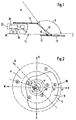
- FIG. 2 shows the projection of a viewing area B, which is delimited by curve 30.
- the curve 30 shows the viewing area B for the selected arrangement of the antenna 10 behind the window 13.
- the vehicle 14 is located in the middle of the axis cross N, O, S, W and travels in the direction of travel D. Circles are shown in dashed lines around the vehicle that correspond to the elevation angles 30 °, 60 ° and 90 °.
- navigation satellites 1 to 7, which orbit the earth are arranged schematically in the axis cross. The satellites have elevation angles between 30 ° and 90 °.
- satellites 1 and 3 are located in the west-north-west and south-east direction with 60 ° elevation, satellites 2 and 4 have an elevation of 40 ° to 50 ° and satellites 5, 6 and 7 are low with an elevation of less than 30 °.
- a maximum of satellites 1 to 5 can thus be received directly, while satellites 6 and 7 cannot be received or can only be received indirectly.
- the reception quality is still dependent on the position relative to the receiving antenna 10, so that not all of these five satellites are generally used to evaluate its signals.
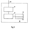
- FIG. 3 schematically shows the controller 20 of a GPS receiver 22.
- the antenna 10 is connected to a decoder 31 on this receiver, which forwards the decoded signals to an evaluation 32.
- the evaluation 32 has a first memory area 33, in which the code names of the receivable satellites and their orbits are stored. Furthermore, the evaluation 32 is connected to a second storage area 34, in which viewing areas B of the antenna 10 which are dependent on the direction of travel are stored.
- the vehicle 14 is located in the center of the coordinate and travels in the direction of travel D according to the dashed arrow. It can thus be seen from the viewing area B that the vehicle device receives the satellites 1 to 5 directly, since these satellites are in the viewing area to the antenna 10. It is further assumed that the signals in areas A or C are also received by satellites 6 and 7, since their signals are reflected in the viewing area B by reflection.
- the GPS receiver 22 cannot distinguish itself as to whether the signals from the satellites 1 to 7 come in directly or indirectly.
- the direction of travel D of the vehicle 14 is first calculated.
- the evaluation 32 now takes the corresponding values for the visual range B from the second memory 34, which values have previously been determined empirically and stored as a function of the direction of travel.
- the names and the orbits are stored in the first storage area 33, so that it can be determined at a certain point in time which of the stored satellites are currently in the viewing area B of the vehicle.
- the evaluation 32 determines, for example, that the satellites 1 to 5 are currently in the viewing area B. It can thus use their signals jointly or partially to determine the position.
- the indirectly incident signals from satellites 6 and 7 are suppressed.
- the position of the viewing area B relative to the satellites also changes. If necessary, other satellites can now be received in the new viewing area, so that the directly incident signals must be selected again from the received signals.
- the viewing area B is determined by the spatial arrangement of the antenna 10 in the vehicle 14. It results from the volume that is formed from the height angle and the wide angle. Since the satellite signal can be deflected by diffraction and reflection in the border area to the vehicle parts 12, an optimization of the viewing area B is provided. In principle, the field of vision can be determined empirically for each direction of travel and the corresponding values can be stored in the second memory 34. For optimization, it is advantageous to carry out several reception measurements of the satellites while traveling in the same direction, if possible in a low-reflection area. The signals from those satellites that are currently in viewing range B are decoded. When driving in the same Direction, these satellites can be received for a certain time.
- Indirectly incoming signals can fail to appear or can only be received very weakly.
- an optimal range for the reception range B can be determined, which is possibly smaller than the range delimited by the vehicle parts 12.
- the viewing area B thus optimized is then used for the further selection of the satellite signals.
- the entire reception area is divided into sub-areas with the parameters elevation and angle relative to the direction of travel.
- a counting cell is assigned to each of these segments. If a satellite is expected in a segment based on its current position and the current direction of travel, but cannot be received, the associated counting cell is counted down, but if it is received as expected, it is counted up. The counter readings of the individual segments are converted into a relative value with the number of counts carried out in the partial area.
- a threshold value can then be defined (eg 75%) that provides information about whether a segment is in the field of view or outside. This is explained in more detail using an example. According to FIG.
- the satellite 6 has the direction angle (azimuth angle) ⁇ ⁇ 290 ° and the elevation angle ⁇ 6 ⁇ 15 °.
- the relative position of the satellite 6 to the vehicle antenna 10 is therefore 325 ° / 15 °.
- the reception area B is divided into predetermined sub-areas. However, since the 325 ° / 15 ° position does not fall in any section, a count is counted down for each section.
Landscapes
- Engineering & Computer Science (AREA)
- Radar, Positioning & Navigation (AREA)
- Remote Sensing (AREA)
- Computer Networks & Wireless Communication (AREA)
- Physics & Mathematics (AREA)
- General Physics & Mathematics (AREA)
- Signal Processing (AREA)
- Position Fixing By Use Of Radio Waves (AREA)
- Navigation (AREA)
- Mobile Radio Communication Systems (AREA)
- Radio Relay Systems (AREA)
Applications Claiming Priority (2)
| Application Number | Priority Date | Filing Date | Title |
|---|---|---|---|
| DE4415083A DE4415083A1 (de) | 1994-04-29 | 1994-04-29 | Verfahren zur Selektion von Signalen von Navigationssatelliten |
| DE4415083 | 1994-04-29 |
Publications (3)
| Publication Number | Publication Date |
|---|---|
| EP0679902A2 true EP0679902A2 (fr) | 1995-11-02 |
| EP0679902A3 EP0679902A3 (fr) | 1995-11-22 |
| EP0679902B1 EP0679902B1 (fr) | 2003-08-20 |
Family
ID=6516835
Family Applications (1)
| Application Number | Title | Priority Date | Filing Date |
|---|---|---|---|
| EP95104999A Expired - Lifetime EP0679902B1 (fr) | 1994-04-29 | 1995-04-04 | Procédé de sélection des signaux de satellites de navigation |
Country Status (4)
| Country | Link |
|---|---|
| US (1) | US5589836A (fr) |
| EP (1) | EP0679902B1 (fr) |
| JP (1) | JP3631799B2 (fr) |
| DE (2) | DE4415083A1 (fr) |
Cited By (1)
| Publication number | Priority date | Publication date | Assignee | Title |
|---|---|---|---|---|
| EP4036324A4 (fr) * | 2019-09-26 | 2023-10-04 | Hitachi Construction Machinery Co., Ltd. | Engin de chantier |
Families Citing this family (14)
| Publication number | Priority date | Publication date | Assignee | Title |
|---|---|---|---|---|
| GB2324218A (en) * | 1997-04-09 | 1998-10-14 | Ico Services Ltd | Satellite acquisition in navigation system |
| DE19856187A1 (de) * | 1998-12-05 | 2000-06-15 | Alcatel Sa | Satellitengestütztes map-matching-Verfahren |
| US6774843B2 (en) | 2001-03-28 | 2004-08-10 | Communications Research Laboratory, Independent Administrative Institution | Method for acquiring azimuth information |
| GB2378835B (en) | 2001-03-28 | 2003-10-15 | Comm Res Lab | Method for acquiring azimuth information |
| JP4088490B2 (ja) * | 2002-07-25 | 2008-05-21 | 株式会社エヌ・ティ・ティ・ドコモ | 移動体の測位装置及び測位方法 |
| KR101154079B1 (ko) | 2005-02-16 | 2012-06-11 | 삼성전자주식회사 | 네비게이션 장치의 초기 위치 결정 방법 |
| JP5425039B2 (ja) | 2010-11-02 | 2014-02-26 | 株式会社豊田中央研究所 | 衛星信号判定装置及びプログラム |
| EP2702429B1 (fr) * | 2011-04-28 | 2016-05-11 | Topcon Positioning Systems, Inc. | Détection et détermination de la position d'un objet au moyen de signaux gnss réfléchis |
| JP6495664B2 (ja) * | 2015-01-19 | 2019-04-03 | 古野電気株式会社 | 方位算出装置、方位算出方法、方位算出プログラム、および、移動体 |
| JP2016217710A (ja) * | 2015-05-14 | 2016-12-22 | 株式会社東芝 | 列車位置検知装置、及び方法 |
| DE102017204321A1 (de) | 2017-03-15 | 2018-09-20 | Robert Bosch Gmbh | Verfahren und Vorrichtung zum Filtern von empfangenen Satellitennavigationssignalen |
| DE102017204615A1 (de) | 2017-03-20 | 2018-09-20 | Robert Bosch Gmbh | Verfahren und Vorrichtung zur Positionsbestimmung und zum Bestimmen eines Laufzeitverlängerungsanteils |
| JP6961636B2 (ja) * | 2019-03-01 | 2021-11-05 | 日立建機株式会社 | 作業機械 |
| JP7419119B2 (ja) * | 2020-03-16 | 2024-01-22 | 日立建機株式会社 | 作業機械 |
Family Cites Families (8)
| Publication number | Priority date | Publication date | Assignee | Title |
|---|---|---|---|---|
| JPH0621792B2 (ja) * | 1986-06-26 | 1994-03-23 | 日産自動車株式会社 | ハイブリツド式位置計測装置 |
| US4912645A (en) * | 1987-03-26 | 1990-03-27 | Mazda Motor Corporation | Automotive navigation system |
| JPH0820504B2 (ja) * | 1987-09-22 | 1996-03-04 | 株式会社豊田中央研究所 | Gps航法装置 |
| JPH02196975A (ja) * | 1989-01-26 | 1990-08-03 | Nissan Motor Co Ltd | 車両用gps航法装置 |
| US5185610A (en) * | 1990-08-20 | 1993-02-09 | Texas Instruments Incorporated | GPS system and method for deriving pointing or attitude from a single GPS receiver |
| JP3198514B2 (ja) * | 1990-12-27 | 2001-08-13 | 株式会社デンソー | 車両用gps受信装置 |
| JPH0739960B2 (ja) * | 1991-06-18 | 1995-05-01 | 住友電気工業株式会社 | 位置検出装置 |
| US5446465A (en) * | 1993-06-18 | 1995-08-29 | Diefes; Debra L. | Satellite location and pointing system for use with global positioning system |
-
1994
- 1994-04-29 DE DE4415083A patent/DE4415083A1/de not_active Ceased
-
1995
- 1995-03-06 US US08/398,701 patent/US5589836A/en not_active Expired - Lifetime
- 1995-04-04 DE DE59510767T patent/DE59510767D1/de not_active Expired - Lifetime
- 1995-04-04 EP EP95104999A patent/EP0679902B1/fr not_active Expired - Lifetime
- 1995-04-28 JP JP10643495A patent/JP3631799B2/ja not_active Expired - Fee Related
Cited By (1)
| Publication number | Priority date | Publication date | Assignee | Title |
|---|---|---|---|---|
| EP4036324A4 (fr) * | 2019-09-26 | 2023-10-04 | Hitachi Construction Machinery Co., Ltd. | Engin de chantier |
Also Published As
| Publication number | Publication date |
|---|---|
| EP0679902B1 (fr) | 2003-08-20 |
| US5589836A (en) | 1996-12-31 |
| JPH07325141A (ja) | 1995-12-12 |
| JP3631799B2 (ja) | 2005-03-23 |
| EP0679902A3 (fr) | 1995-11-22 |
| DE4415083A1 (de) | 1995-11-02 |
| DE59510767D1 (de) | 2003-09-25 |
Similar Documents
| Publication | Publication Date | Title |
|---|---|---|
| EP0679902B1 (fr) | Procédé de sélection des signaux de satellites de navigation | |
| DE4134508C2 (fr) | ||
| DE4033527C2 (de) | Fahrzeugpositionsdetektoreinrichtung | |
| DE60031868T2 (de) | Navigationssystem und -verfahren zum verfolgen der position eines objektes | |
| DE4142403C2 (de) | GPS-Signal-Empfangssystem für ein Fahrzeug | |
| DE69306523T2 (de) | Navigationsvorrichtung | |
| DE19645209B4 (de) | Ortungsvorrichtung für ein Kraftfahrzeug mit einem Satellitenempfänger und Ortungsverfahren | |
| EP3776000A1 (fr) | Procédé de détermination de la position d'un véhicule | |
| EP1279003B1 (fr) | Procede de determination de position et appareil de navigation | |
| DE102018214961A1 (de) | Verfahren zur Erkennung von Winkelmessfehlern bei einem Radarsensor | |
| DE19705740B4 (de) | GPS-Satelliten verwendendes Positionsbestimmungssystem | |
| DE112012006602T5 (de) | Positioniervorrichtung | |
| DE10310214A1 (de) | Verfahren zum Erfassen von Umgebungsinformationen und Verfahren zum Bestimmen der Lage einer Parklücke | |
| DE69700177T2 (de) | Fahrzeugnavigationssystem mit automatischer Kalibrierung der Bordsensoren | |
| DE102008054579A1 (de) | Dejustageerkennung für einen Radarsensor | |
| DE102008034230A1 (de) | Verfahren zur Bestimmung einer Fahrzeugposition | |
| DE69723296T2 (de) | Verfahren und vorrichtung zum kalibrieren von spurweite | |
| EP1012627A2 (fr) | Procede de mesure optoelectronique et dispositif de mesure optoelectronique | |
| WO2010022693A1 (fr) | Procédé et dispositif de localisation d'un véhicule | |
| WO2021008971A1 (fr) | Procédé de génération d'un modèle d'environnement tridimensionnel à l'aide de mesures gnss | |
| DE3901040C1 (fr) | ||
| DE2843956C2 (de) | LORAN-C-Empfänger | |
| DE102017204615A1 (de) | Verfahren und Vorrichtung zur Positionsbestimmung und zum Bestimmen eines Laufzeitverlängerungsanteils | |
| EP2307900B1 (fr) | Dispositif et procédé de détermination d'une position | |
| DE10028900A1 (de) | Navigationssystem und Verfahren zur Positionsbestimmung und/oder zur Richtungsbestimmung |
Legal Events
| Date | Code | Title | Description |
|---|---|---|---|
| PUAI | Public reference made under article 153(3) epc to a published international application that has entered the european phase |
Free format text: ORIGINAL CODE: 0009012 |
|
| PUAL | Search report despatched |
Free format text: ORIGINAL CODE: 0009013 |
|
| AK | Designated contracting states |
Kind code of ref document: A2 Designated state(s): CH DE FR GB LI NL |
|
| AK | Designated contracting states |
Kind code of ref document: A3 Designated state(s): CH DE FR GB LI NL |
|
| 17P | Request for examination filed |
Effective date: 19960522 |
|
| 17Q | First examination report despatched |
Effective date: 19981123 |
|
| GRAH | Despatch of communication of intention to grant a patent |
Free format text: ORIGINAL CODE: EPIDOS IGRA |
|
| GRAH | Despatch of communication of intention to grant a patent |
Free format text: ORIGINAL CODE: EPIDOS IGRA |
|
| GRAA | (expected) grant |
Free format text: ORIGINAL CODE: 0009210 |
|
| RBV | Designated contracting states (corrected) |
Designated state(s): CH DE FR GB IT LI NL |
|
| AK | Designated contracting states |
Designated state(s): CH DE FR GB IT LI NL |
|
| PG25 | Lapsed in a contracting state [announced via postgrant information from national office to epo] |
Ref country code: NL Free format text: LAPSE BECAUSE OF FAILURE TO SUBMIT A TRANSLATION OF THE DESCRIPTION OR TO PAY THE FEE WITHIN THE PRESCRIBED TIME-LIMIT Effective date: 20030820 Ref country code: GB Free format text: LAPSE BECAUSE OF FAILURE TO SUBMIT A TRANSLATION OF THE DESCRIPTION OR TO PAY THE FEE WITHIN THE PRESCRIBED TIME-LIMIT Effective date: 20030820 |
|
| REG | Reference to a national code |
Ref country code: GB Ref legal event code: FG4D Free format text: NOT ENGLISH |
|
| REG | Reference to a national code |
Ref country code: CH Ref legal event code: EP |
|
| REF | Corresponds to: |
Ref document number: 59510767 Country of ref document: DE Date of ref document: 20030925 Kind code of ref document: P |
|
| NLV1 | Nl: lapsed or annulled due to failure to fulfill the requirements of art. 29p and 29m of the patents act | ||
| GBV | Gb: ep patent (uk) treated as always having been void in accordance with gb section 77(7)/1977 [no translation filed] |
Effective date: 20030820 |
|
| PG25 | Lapsed in a contracting state [announced via postgrant information from national office to epo] |
Ref country code: LI Free format text: LAPSE BECAUSE OF NON-PAYMENT OF DUE FEES Effective date: 20040430 Ref country code: CH Free format text: LAPSE BECAUSE OF NON-PAYMENT OF DUE FEES Effective date: 20040430 |
|
| ET | Fr: translation filed | ||
| PLBE | No opposition filed within time limit |
Free format text: ORIGINAL CODE: 0009261 |
|
| STAA | Information on the status of an ep patent application or granted ep patent |
Free format text: STATUS: NO OPPOSITION FILED WITHIN TIME LIMIT |
|
| 26N | No opposition filed |
Effective date: 20040524 |
|
| REG | Reference to a national code |
Ref country code: CH Ref legal event code: PL |
|
| PGFP | Annual fee paid to national office [announced via postgrant information from national office to epo] |
Ref country code: FR Payment date: 20110427 Year of fee payment: 17 |
|
| PGFP | Annual fee paid to national office [announced via postgrant information from national office to epo] |
Ref country code: IT Payment date: 20110427 Year of fee payment: 17 |
|
| REG | Reference to a national code |
Ref country code: FR Ref legal event code: ST Effective date: 20121228 |
|
| PG25 | Lapsed in a contracting state [announced via postgrant information from national office to epo] |
Ref country code: FR Free format text: LAPSE BECAUSE OF NON-PAYMENT OF DUE FEES Effective date: 20120430 Ref country code: IT Free format text: LAPSE BECAUSE OF NON-PAYMENT OF DUE FEES Effective date: 20120404 |
|
| PGFP | Annual fee paid to national office [announced via postgrant information from national office to epo] |
Ref country code: DE Payment date: 20130627 Year of fee payment: 19 |
|
| REG | Reference to a national code |
Ref country code: DE Ref legal event code: R119 Ref document number: 59510767 Country of ref document: DE |
|
| PG25 | Lapsed in a contracting state [announced via postgrant information from national office to epo] |
Ref country code: DE Free format text: LAPSE BECAUSE OF NON-PAYMENT OF DUE FEES Effective date: 20141101 |
|
| REG | Reference to a national code |
Ref country code: DE Ref legal event code: R119 Ref document number: 59510767 Country of ref document: DE Effective date: 20141101 |