EP0679902A2 - Method of selection of signals of navigation satellites - Google Patents
Method of selection of signals of navigation satellites Download PDFInfo
- Publication number
- EP0679902A2 EP0679902A2 EP95104999A EP95104999A EP0679902A2 EP 0679902 A2 EP0679902 A2 EP 0679902A2 EP 95104999 A EP95104999 A EP 95104999A EP 95104999 A EP95104999 A EP 95104999A EP 0679902 A2 EP0679902 A2 EP 0679902A2
- Authority
- EP
- European Patent Office
- Prior art keywords
- vehicle
- signals
- antenna
- satellites
- travel
- Prior art date
- Legal status (The legal status is an assumption and is not a legal conclusion. Google has not performed a legal analysis and makes no representation as to the accuracy of the status listed.)
- Granted
Links
Images
Classifications
-
- G—PHYSICS
- G01—MEASURING; TESTING
- G01S—RADIO DIRECTION-FINDING; RADIO NAVIGATION; DETERMINING DISTANCE OR VELOCITY BY USE OF RADIO WAVES; LOCATING OR PRESENCE-DETECTING BY USE OF THE REFLECTION OR RERADIATION OF RADIO WAVES; ANALOGOUS ARRANGEMENTS USING OTHER WAVES
- G01S19/00—Satellite radio beacon positioning systems; Determining position, velocity or attitude using signals transmitted by such systems
- G01S19/01—Satellite radio beacon positioning systems transmitting time-stamped messages, e.g. GPS [Global Positioning System], GLONASS [Global Orbiting Navigation Satellite System] or GALILEO
- G01S19/13—Receivers
- G01S19/35—Constructional details or hardware or software details of the signal processing chain
- G01S19/36—Constructional details or hardware or software details of the signal processing chain relating to the receiver frond end
-
- G—PHYSICS
- G01—MEASURING; TESTING
- G01S—RADIO DIRECTION-FINDING; RADIO NAVIGATION; DETERMINING DISTANCE OR VELOCITY BY USE OF RADIO WAVES; LOCATING OR PRESENCE-DETECTING BY USE OF THE REFLECTION OR RERADIATION OF RADIO WAVES; ANALOGOUS ARRANGEMENTS USING OTHER WAVES
- G01S19/00—Satellite radio beacon positioning systems; Determining position, velocity or attitude using signals transmitted by such systems
- G01S19/01—Satellite radio beacon positioning systems transmitting time-stamped messages, e.g. GPS [Global Positioning System], GLONASS [Global Orbiting Navigation Satellite System] or GALILEO
- G01S19/13—Receivers
- G01S19/24—Acquisition or tracking or demodulation of signals transmitted by the system
- G01S19/28—Satellite selection
-
- G—PHYSICS
- G01—MEASURING; TESTING
- G01S—RADIO DIRECTION-FINDING; RADIO NAVIGATION; DETERMINING DISTANCE OR VELOCITY BY USE OF RADIO WAVES; LOCATING OR PRESENCE-DETECTING BY USE OF THE REFLECTION OR RERADIATION OF RADIO WAVES; ANALOGOUS ARRANGEMENTS USING OTHER WAVES
- G01S19/00—Satellite radio beacon positioning systems; Determining position, velocity or attitude using signals transmitted by such systems
- G01S19/38—Determining a navigation solution using signals transmitted by a satellite radio beacon positioning system
- G01S19/39—Determining a navigation solution using signals transmitted by a satellite radio beacon positioning system the satellite radio beacon positioning system transmitting time-stamped messages, e.g. GPS [Global Positioning System], GLONASS [Global Orbiting Navigation Satellite System] or GALILEO
- G01S19/42—Determining position
Definitions
- the invention is based on a method or a receiving device for the selection of received signals from navigation satellites, for example the GPA, GLONASS or similar satellite systems according to the category of the independent claims 1 and 6.
- the signals of several satellites are evaluated for the current position determination, orbiting the earth on certain predetermined orbits.
- a receiver can determine the exact distance to the satellite whose current position in the receiver is known (for example, by information that is transmitted from the satellite to the receiver). Knowing the position of three satellites and the distance to them is enough to clearly determine the location of the receiver down to a few meters. If the receiver is located in a motor vehicle, for example, which partially obscures the reception area by vehicle parts, then not all satellites that appear suitable for determining the position can be received.
- the method according to the invention or the receiving device according to the independent claims 1 and 6 has the advantage that only those signals are actually evaluated whose satellites are in the field of view of the antenna and whose signals therefore fall directly on the antenna.
- the reflected signals from satellites that are not in the field of view of the antenna are suppressed. This advantageously increases the reliability of the position determination.
- the viewing area is optimized by comparing a newly determined viewing area with the previous, saved viewing area in the case of repeated measurements, so that the largest possible viewing area depending on the direction of travel is determined by several measurement attempts.
- the receivable satellites are determined by their orbits, depending on the direction of travel, only very specific satellites can be received at a certain point in time. To determine the direction of travel of the vehicle vehicle sensors or a corresponding compass are therefore advantageously used. However, it is also possible to derive the direction of travel from the satellite signals themselves, for example by evaluating the Doppler shift in the carrier frequency.
- a GPS receiver is advantageously used for map-based navigation in order to control or, if necessary, correct the position of the vehicle navigation device.
- An advantageous installation location for the antenna of a GPS receiver is, for example, inside the vehicle in the area of the rear or front window.
- the antenna can also be concealed under the parcel shelf or the dashboard, so that it is not visible and is therefore also protected from damage.
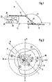
- FIG. 1 shows a schematic arrangement of the antenna in a vehicle
- FIG. 2 shows a projection of a viewing area
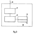
- FIG. 3 shows a block diagram of a GPS receiver.
- FIG 1 shows schematically the arrangement of an antenna 10 in a vehicle 14.
- the vehicle parts 12 are shown as a roof and tailgate.
- a rear window 13 can be seen, behind which an antenna 10 of a GPS receiver 22 is arranged, for example on a rear shelf 17.
- the antenna 10 is partially shaded by the vehicle parts 12, so that a limited by the rear window or windshield 13 Viewing area B results. Signals from the subsequent areas A, C cannot be received by the antenna 10 because the vehicle parts 12 shield the signals.
- the antenna 10 can thus receive the signals from the GPS satellites that are in the viewing area B. In this viewing area B, of course, there are also signals that are sent from satellites located outside this viewing area, but whose signals are on house walls, mountains and the like. ⁇ . are reflected. These signals distort the position determination and are therefore not desirable.
- a GPS receiver 22 is shown schematically in FIG. 1, which has a control 20 and a corresponding data output 21.
- the controller is preferably connected to one or more wheel sensors 15 or a compass 16.
- the wheel sensors 15 or the compass 16 can thus enter the direction of travel or the north direction of the vehicle into the GPS receiver 22.
- the GPS receiver 22 is known per se and therefore need not be described in detail. Instead of the wheel sensors 15, suitable inertial sensors (gyrometers) can also be used.
- the direction of travel can also be determined from the satellite signals by measuring the Doppler shift or the carrier phase.
- FIG. 2 shows the projection of a viewing area B, which is delimited by curve 30.
- the curve 30 shows the viewing area B for the selected arrangement of the antenna 10 behind the window 13.
- the vehicle 14 is located in the middle of the axis cross N, O, S, W and travels in the direction of travel D. Circles are shown in dashed lines around the vehicle that correspond to the elevation angles 30 °, 60 ° and 90 °.
- navigation satellites 1 to 7, which orbit the earth are arranged schematically in the axis cross. The satellites have elevation angles between 30 ° and 90 °.
- satellites 1 and 3 are located in the west-north-west and south-east direction with 60 ° elevation, satellites 2 and 4 have an elevation of 40 ° to 50 ° and satellites 5, 6 and 7 are low with an elevation of less than 30 °.
- a maximum of satellites 1 to 5 can thus be received directly, while satellites 6 and 7 cannot be received or can only be received indirectly.
- the reception quality is still dependent on the position relative to the receiving antenna 10, so that not all of these five satellites are generally used to evaluate its signals.
- FIG. 3 schematically shows the controller 20 of a GPS receiver 22.
- the antenna 10 is connected to a decoder 31 on this receiver, which forwards the decoded signals to an evaluation 32.
- the evaluation 32 has a first memory area 33, in which the code names of the receivable satellites and their orbits are stored. Furthermore, the evaluation 32 is connected to a second storage area 34, in which viewing areas B of the antenna 10 which are dependent on the direction of travel are stored.
- the vehicle 14 is located in the center of the coordinate and travels in the direction of travel D according to the dashed arrow. It can thus be seen from the viewing area B that the vehicle device receives the satellites 1 to 5 directly, since these satellites are in the viewing area to the antenna 10. It is further assumed that the signals in areas A or C are also received by satellites 6 and 7, since their signals are reflected in the viewing area B by reflection.
- the GPS receiver 22 cannot distinguish itself as to whether the signals from the satellites 1 to 7 come in directly or indirectly.
- the direction of travel D of the vehicle 14 is first calculated.
- the evaluation 32 now takes the corresponding values for the visual range B from the second memory 34, which values have previously been determined empirically and stored as a function of the direction of travel.
- the names and the orbits are stored in the first storage area 33, so that it can be determined at a certain point in time which of the stored satellites are currently in the viewing area B of the vehicle.
- the evaluation 32 determines, for example, that the satellites 1 to 5 are currently in the viewing area B. It can thus use their signals jointly or partially to determine the position.
- the indirectly incident signals from satellites 6 and 7 are suppressed.
- the position of the viewing area B relative to the satellites also changes. If necessary, other satellites can now be received in the new viewing area, so that the directly incident signals must be selected again from the received signals.
- the viewing area B is determined by the spatial arrangement of the antenna 10 in the vehicle 14. It results from the volume that is formed from the height angle and the wide angle. Since the satellite signal can be deflected by diffraction and reflection in the border area to the vehicle parts 12, an optimization of the viewing area B is provided. In principle, the field of vision can be determined empirically for each direction of travel and the corresponding values can be stored in the second memory 34. For optimization, it is advantageous to carry out several reception measurements of the satellites while traveling in the same direction, if possible in a low-reflection area. The signals from those satellites that are currently in viewing range B are decoded. When driving in the same Direction, these satellites can be received for a certain time.
- Indirectly incoming signals can fail to appear or can only be received very weakly.
- an optimal range for the reception range B can be determined, which is possibly smaller than the range delimited by the vehicle parts 12.
- the viewing area B thus optimized is then used for the further selection of the satellite signals.
- the entire reception area is divided into sub-areas with the parameters elevation and angle relative to the direction of travel.
- a counting cell is assigned to each of these segments. If a satellite is expected in a segment based on its current position and the current direction of travel, but cannot be received, the associated counting cell is counted down, but if it is received as expected, it is counted up. The counter readings of the individual segments are converted into a relative value with the number of counts carried out in the partial area.
- a threshold value can then be defined (eg 75%) that provides information about whether a segment is in the field of view or outside. This is explained in more detail using an example. According to FIG.
- the satellite 6 has the direction angle (azimuth angle) ⁇ ⁇ 290 ° and the elevation angle ⁇ 6 ⁇ 15 °.
- the relative position of the satellite 6 to the vehicle antenna 10 is therefore 325 ° / 15 °.
- the reception area B is divided into predetermined sub-areas. However, since the 325 ° / 15 ° position does not fall in any section, a count is counted down for each section.
Abstract
Description
Die Erfindung geht aus von einem Verfahren bzw. einem Empfangsgerät zur Selektion von empfangenen Signalen von Navigationssatelliten, beispielsweise der GPA-, GLONASS- oder ähnlicher Satellitensysteme nach der Gattung der nebengeordneten Ansprüche 1 und 6. Zur momentanen Positionsbestimmung werden dabei die Signale mehrerer Satelliten ausgewertet, die auf bestimmten vorgegebenen Bahnen die Erde umkreisen. Aufgrund von Laufzeitmessungen kann ein Empfänger die genaue Entfernung zum Satelliten bestimmen, dessen derzeitige Position im Empfänger bekannt ist (z.B. durch Angaben, die vom Satelliten an den Empfänger übertragen werden). Die Kenntnis der Position von drei Satelliten und des Abstandes zu ihnen genügt, um den Ort des Empfängers eindeutig bis auf wenige Meter genau zu bestimmen. Befindet sich der Empfänger beispielsweise in einem Kraftfahrzeug, das den Empfangsbereich durch Fahrzeugteile teilweise abgeschattet, dann können nicht alle zur Positionsbestimmung geeignet erscheinende Satelliten empfangen werden. Andererseits können durch Reflexionen an Häuserwänden oder Bergen Satellitensignale empfangen werden, die eine falsche Position des Satelliten vortäuschen. Der Empfänger kann diese unterschiedlichen Signale von sich aus jedoch nicht unterscheiden, so daß es teilweise zu Fehlbestimmungen der Position kommt. Derartige Fehlbestimmungen sind unerwünscht, da sie die Zuverlässigkeit des Gerätes stark beeinträchtigen können.The invention is based on a method or a receiving device for the selection of received signals from navigation satellites, for example the GPA, GLONASS or similar satellite systems according to the category of the
Das erfindungsgemäße Verfahren beziehungsweise das Empfangsgerät nach den nebengeordneten Ansprüchen 1 und 6 hat demgegenüber den Vorteil, daß tatsächlich nur die Signale ausgewertet werden, deren Satelliten im Sichtbereich der Antenne liegen und deren Signale daher direkt auf die Antenne fallen. Die reflektierten Signale von Satelliten, die nicht im Sichtbereich der Antenne liegen, werden unterdrückt. Dadurch wird vorteilhaft die Zuverlässigkeit der Positionsbestimmung erhöht.The method according to the invention or the receiving device according to the
Durch die in den abhängigen Ansprüchen aufgeführten Maßnahmen sind vorteilhafte Weiterbildungen und Verbesserungen des im Anspruch 1 angegebenen Verfahrens beziehungsweise des Empfangsgeräts nach Anspruch 6 möglich. Besonders vorteilhaft ist, daß durch die wiederholte Bestimmung der Größe oder der Weite des Sichtbereichs das Erkennungsfeld für die Satelliten optimiert wird, so daß je nach Fahrtrichtung und Zeitpunkt alle Satelliten, die im Sichtbereich der Antenne liegen und für die Positionsbestimmung genutzt werden können.The measures listed in the dependent claims allow advantageous developments and improvements of the method specified in
Eine Optimierung des Sichtbereichs ergibt sich dadurch, daß bei wiederholten Messungen ein neu ermittelter Sichtbereich mit vorherigem, gespeicherten Sichtbereich verglichen wird, so daß durch mehrere Meßversuche der größtmögliche Sichtbereich in Abhängigkeit von der Fahrtrichtung ermittelt wird.The viewing area is optimized by comparing a newly determined viewing area with the previous, saved viewing area in the case of repeated measurements, so that the largest possible viewing area depending on the direction of travel is determined by several measurement attempts.
Da die empfangbaren Satelliten durch ihre Umlaufbahnen festgelegt sind, können - je nach Fahrtrichtung - zu einem bestimmten Zeitpunkt nur ganz bestimmte Satelliten empfangen werden. Zur Bestimmung der Fahrtrichtung des Fahrzeugs werden daher vorteilhaft Fahrzeugsensoren oder ein entsprechender Kompass verwendet. Es ist aber auch möglich, die Fahrtrichtung aus den Satellitensignalen selbst herzuleiten, z.B. durch Auswertung der Doppler-Verschiebung der Trägerfrequenz.Since the receivable satellites are determined by their orbits, depending on the direction of travel, only very specific satellites can be received at a certain point in time. To determine the direction of travel of the vehicle vehicle sensors or a corresponding compass are therefore advantageously used. However, it is also possible to derive the direction of travel from the satellite signals themselves, for example by evaluating the Doppler shift in the carrier frequency.
Für eine kartengestützte Navigation wird vorteilhaft ein GPS-Empfänger verwendet, um die Position des Fahrzeug-Navigationsgeräts zu kontrollieren oder gegebenenfalls zu korrigieren.A GPS receiver is advantageously used for map-based navigation in order to control or, if necessary, correct the position of the vehicle navigation device.
Ein vorteilhaft Einbauort für die Antenne eines GPS-Empfängers ist beispielsweise innerhalb des Fahrzeugs im Bereich der Heck- oder Frontscheibe gegeben. Auch kann die Antenne verdeckt unter der Hutablage oder dem Armaturenbrett angeordnet sein, so daß sie nicht sichtbar ist und daher auch vor Beschädigungen geschützt ist.An advantageous installation location for the antenna of a GPS receiver is, for example, inside the vehicle in the area of the rear or front window. The antenna can also be concealed under the parcel shelf or the dashboard, so that it is not visible and is therefore also protected from damage.
Ein Ausführungsbeispiel der Erfindung ist in der Zeichnung dargestellt und in der Beschreibung näher erläutert. Es zeigen Figur 1 eine schematische Anordnung der Antenne in einem Fahrzeug, Figur 2 zeigt eine Projektion eines Sichtbereichs und Figur 3 zeigt ein Blockschaltbild eines GPS-Empfängers.An embodiment of the invention is shown in the drawing and explained in more detail in the description. FIG. 1 shows a schematic arrangement of the antenna in a vehicle, FIG. 2 shows a projection of a viewing area and FIG. 3 shows a block diagram of a GPS receiver.
Figur 1 zeigt schematisch die Anordnung einer Antenne 10 in einem Fahrzeug 14. Im Schnittbild der Figur 1 sind die Fahrzeugteile 12 als Dach und Heckklappe dargestellt. Des weiteren ist eine Heckscheibe 13 erkennbar, hinter der beispielsweise auf einer Hutablage 17 eine Antenne 10 eines GPS-Empfängers 22 angeordnet ist. Die Antenne 10 wird teilweise durch die Fahrzeugteile 12 abgeschattet, so daß sich durch die Heckscheibe oder auch Frontscheibe 13 ein beschränkter Sichtbereich B ergibt. Signale aus den anschließenden Bereichen A, C können von der Antenne 10 nicht empfangen werden, da die Fahrzeugteile 12 die Signale abschirmen. Die Antenne 10 kann somit die Signale der GPS-Satelliten empfangen, die im Sichtbereich B liegen. In diesen Sichtbereich B fallen natürlich auch solche Signale ein, die von außerhalb dieses Sichtbereichs befindlichen Satelliten gesendet werden, deren Signale aber an Hauswänden, Bergen u. ä. reflektiert werden. Diese Signale verfälschen die Positionsbestimmung und sind daher nicht erwünscht.Figure 1 shows schematically the arrangement of an
In Figur 1 ist schematisch noch ein GPS-Empfänger 22 dargestellt, der eine Steuerung 20, sowie eine entsprechende Datenausgabe 21 aufweist. Die Steuerung ist vorzugsweise mit einem oder mehreren Radsensoren 15 oder einem Kompass 16 verbunden. Die Radsensoren 15 oder der Kompass 16 können somit die Fahrtrichtung oder die Nordrichtung des Fahrzeugs in den GPS-Empfänger 22 eingeben. Der GPS-Empfänger 22 ist per se bekannt und muß daher nicht näher beschrieben werden. Anstelle der Radsensoren 15 können auch geeignete Trägheitssensoren (Gyrometer) verwendet werden. Auch läßt sich die Fahrtrichtung aus den Satellitensignalen durch Messung der Doppler-Verschiebung oder der Trägerphase ermitteln.A
Figur 2 zeigt die Projektion eines Sichtbereich B, der durch die Kurve 30 begrenzt ist. Die Kurve 30 ergibt den Sichtbereich B für die gewählte Anordnung der Antenne 10 hinter der Scheibe 13. Beispielsweise befindet sich das Fahrzeug 14 in der Mitte des Achsenkreuzes N, O, S, W und fährt in Fahrtrichtung D. Um das Fahrzeug sind gestrichelt Kreise dargestellt, die den Elevationswinkeln 30°, 60° und 90° entsprechen. Des weiteren sind im Achsenkreuz schematisch Navigationssatelliten 1 bis 7 angeordnet, die um die Erde kreisen. Die Satelliten haben Elevationswinkel zwischen 30° und 90°. Beispielsweise befinden sich die Satelliten 1 und 3 in West-Nord-West- bzw. Süd-Ost-Richtung mit 60°-Elevation, der Satellit 2 und 4 hat eine Elevation von 40°bis 50° und die Satelliten 5, 6 und 7 stehen tief mit einer Elevation unter 30°. Innerhalb des Sichtbereichs B können somit maximal die Satelliten 1 bis 5 direkt empfangen werden, währen die Satelliten 6 und 7 nicht oder nur indirekt empfangen werden können. Von den empfangbaren Satelliten 1 bis 5 ist die Empfangsqualität noch abhängig von der relativen Position zur Empfangsantenne 10, so daß in der Regel nicht jeder dieser fünf Satelliten zur Auswertung seiner Signale verwendet wird.FIG. 2 shows the projection of a viewing area B, which is delimited by
Figur 3 zeigt schematisch die Steuerung 20 eines GPS-Empfängers 22. An diesem Empfänger ist die Antenne 10 mit einem Decoder 31 verbunden, der die decodierten Signale an eine Auswertung 32 weiterleitet. Die Auswertung 32 hat einen ersten Speicherbereich 33, in dem Codenamen der empfangbaren Satelliten sowie deren Umlaufbahnen gespeichert sind. Des weiteren ist die Auswertung 32 mit einem zweiten Speicherbereich 34 verbunden, in dem fahrtrichtungsabhängige Sichtbereiche B der Antenne 10 gespeichert sind.FIG. 3 schematically shows the
Im folgenden wird anhand des Ausführungsbeispiels das Verfahren beziehungsweise das entsprechende Empfangsgerät zur Durchführung der Selektion von direkt einfallenden und reflektierten beziehungsweise indirekt einfallenden Signalen näher erläutert. Es wird angenommen, daß bezüglich der Figur 2 das Fahrzeug 14 sich im Koordinatenmittelpunkt befindet und entsprechend dem gestrichelten Pfeil in die Fahrtrichtung D fährt. Dem Sichtbereich B ist somit entnehmbar, daß das Fahrzeuggerät die Satelliten 1 bis 5 direkt empfängt, da diese Satelliten im Sichtbereich zur Antenne 10 liegen. Es wird weiter angenommen, daß auch die Signale in den Bereichen A oder C von den Satelliten 6 und 7 empfangen werden, da deren Signale durch Reflektion in den Sichtbereich B reflektiert werden. Der GPS-Empfänger 22 kann von sich aus nicht unterscheiden, ob die Signale des Satelliten 1 bis 7 direkt oder indirekt einfallen. Zur Ermittlung der direkt einfallenden Satellitensignale wird zunächst die Fahrtrichtung D des Fahrzeugs 14 berechnet. Aufgrund der Fahrtrichtung D entnimmt nun die Auswertung 32 dem zweiten Speicher 34 die entsprechenden Werte für den Sichtbereich B, die zuvor beispielsweise empirisch ermittelt und in Abhängigkeit von der Fahrtrichtung abgespeichert wurden. Im ersten Speicherbereich 33 sind die Namen und die Umlaufbahnen gespeichert, so daß zu einem bestimmten Zeitpunkt ermittelt werden kann, welche der gespeicherten Satelliten sich gerade im Sichtbereich B des Fahrzeugs befinden. Die Auswertung 32 stellt beispielsweise fest, daß die Satelliten 1 bis 5 sich gerade im Sichtbereich B befinden. Sie kann somit deren Signale gemeinsam oder teilweise zur Positionsbestimmung heranziehen. Die indirekt einfallenden Signale der Satelliten 6 und 7 werden dabei unterdrückt.The method and the corresponding receiving device for carrying out the selection of directly incident and reflected or indirectly incident signals are explained in more detail below on the basis of the exemplary embodiment. It is assumed that with respect to FIG. 2, the
Ändert sich die Fahrtrichtung D des Fahrzeugs 14, dann ändert sich damit auch die Lage des Sichtbereichs B relativ zu den Satelliten. In dem neuen Sichtbereich können nunmehr gegebenenfalls andere Satelliten empfangen werden, so daß erneut von den empfangenen Signalen die direkt einfallenden Signale ausgewählt werden müssen.If the direction of travel D of the
Der Sichtbereich B ist durch die räumliche Anordnung der Antenne 10 im Fahrzeug 14 bestimmt. Er ergibt sich aus dem Volumen, das aus dem Höhenwinkel und dem weiten Winkel gebildet wird. Da im Grenzbereich zu den Fahrzeugteilen 12 das Satellitensignal durch Beugung und Reflexion abgelenkt werden kann, ist eine Optimierung des Sichtbereichs B vorgesehen. Prinzipiell kann der Sichtbereich empirisch für jede Fahrtrichtung ermittelt werden und die entsprechenden Werte in dem zweiten Speicher 34 abgelegt sein. Zur Optimierung ist es vorteilhaft, während einer Fahrt in die gleiche Richtung, möglichst in einem reflexionsarmen Gebiet, mehrere Empfangsmessungen der Satelliten durchzuführen. Dabei werden die Signale derjenigen Satelliten decodiert, die sich gerade im Sichtbereich B befinden. Bei einer Fahrt in die gleiche Richtung können diese Satelliten für eine gewisse Zeit empfangen werden. Indirekt einfallende Signale können dabei ausbleiben oder nur sehr schwach empfangen werden. Durch Vergleich mit vorher gespeicherten Messungen kann somit ein optimaler Bereich für den Empfangsbereich B festgelegt werden, der unter Umständen kleiner ist als der durch die Fahrzeugteile 12 begrenzte Bereich. Der so optimierte Sichtbereich B wird dann für die weitere Selektion der Satellitensignale verwendet.The viewing area B is determined by the spatial arrangement of the
In weiterer Ausgestaltung der Erfindung ist vorgesehen, daß der gesamte Empfangsbereich in Teilbereiche mit den Parametern Elevation und Winkel relativ zur Fahrtrichtung aufgeteilt wird. Jedem dieser Segmente wird eine Zählzelle zugeordnet. Wird ein Satellit nach seiner aktuellen Position und der aktuellen Fahrtrichtung in einem Segment erwartet, kann aber nicht empfangen werden, so wird die zugehörige Zählzelle herabgezählt, wird es aber erwartungsgemäß empfangen, so wird sie heraufgezählt. Die Zählerstände der einzelnen Segmente werden mit der Anzahl der in dem Teilbereich durchgeführten Zählungen in einen relativen Wert umgewandelt. Dann kann ein Schwellwert definiert werden (z.B. 75%), der eine Aussage darüber liefert, ob ein Segment im Sichtbereich oder außerhalb liegt. Anhand eines Beispiels wird dies näher erläutert. Der Satellit 6 hat gemäß Figur 2 den Richtungswinkel (Azimutwinkel) α ≈ 290° und den Elevationswinkel β₆ ≈ 15°. Das Fahrzeug 14 hat einen Fahrwinkel γ ≈ 315°, d.h. relativ zum Fahrzeug 14 beträgt der Azimutwinkel des Satelliten 6 etwa 280°-315° = -35° bzw. im positiven Wertebereich zwischen 0 und 360° ergibt sich der Winkel +325°. Di e relative Position des Satelliten 6 zur Fahrzeugantenne 10 ist daher 325°/15°. Der Empfangsbereich B ist in vorgegebene Teilbereiche eingeteilt. Da die Position 325°/15° jedoch in keinen Teilbereich fällt, wird ein Zählwert für jeden Teilbereich herabgezählt.In a further embodiment of the invention it is provided that the entire reception area is divided into sub-areas with the parameters elevation and angle relative to the direction of travel. A counting cell is assigned to each of these segments. If a satellite is expected in a segment based on its current position and the current direction of travel, but cannot be received, the associated counting cell is counted down, but if it is received as expected, it is counted up. The counter readings of the individual segments are converted into a relative value with the number of counts carried out in the partial area. A threshold value can then be defined (eg 75%) that provides information about whether a segment is in the field of view or outside. This is explained in more detail using an example. According to FIG. 2, the satellite 6 has the direction angle (azimuth angle) α ≈ 290 ° and the elevation angle β₆ ≈ 15 °. The
Der Satellit 5 hat dagegen die Koordinaten 80°/15° oder relativ zum Fahrzeug 80°-315° = -235° bzw. +125°. Die Position ist also 125°/15°. Sie liegt in einem Teilbereich, so daß beim Abfragen der Teilbereiche der Zähler für diesen Teilbereich heraufgesetzt wird. Bei wiederholten Messungen erhält man so eine Häufigkeitsverteilung. Wird dabei ein Satellit in einem Teilbereich häufiger als z.B. 75% gemessen, dann wird davon ausgegangen, daß dessen Signale direkt empfangen wurden. Im anderen Fall waren es vielleicht nur reflektierte Signale.In contrast, the
Claims (10)
Applications Claiming Priority (2)
| Application Number | Priority Date | Filing Date | Title |
|---|---|---|---|
| DE4415083A DE4415083A1 (en) | 1994-04-29 | 1994-04-29 | Procedure for the selection of signals from navigation satellites |
| DE4415083 | 1994-04-29 |
Publications (3)
| Publication Number | Publication Date |
|---|---|
| EP0679902A2 true EP0679902A2 (en) | 1995-11-02 |
| EP0679902A3 EP0679902A3 (en) | 1995-11-22 |
| EP0679902B1 EP0679902B1 (en) | 2003-08-20 |
Family
ID=6516835
Family Applications (1)
| Application Number | Title | Priority Date | Filing Date |
|---|---|---|---|
| EP95104999A Expired - Lifetime EP0679902B1 (en) | 1994-04-29 | 1995-04-04 | Method of selection of signals of navigation satellites |
Country Status (4)
| Country | Link |
|---|---|
| US (1) | US5589836A (en) |
| EP (1) | EP0679902B1 (en) |
| JP (1) | JP3631799B2 (en) |
| DE (2) | DE4415083A1 (en) |
Cited By (1)
| Publication number | Priority date | Publication date | Assignee | Title |
|---|---|---|---|---|
| EP4036324A4 (en) * | 2019-09-26 | 2023-10-04 | Hitachi Construction Machinery Co., Ltd. | Work machine |
Families Citing this family (13)
| Publication number | Priority date | Publication date | Assignee | Title |
|---|---|---|---|---|
| GB2324218A (en) * | 1997-04-09 | 1998-10-14 | Ico Services Ltd | Satellite acquisition in navigation system |
| DE19856187A1 (en) * | 1998-12-05 | 2000-06-15 | Alcatel Sa | Satellite-based map matching process |
| GB2378835B (en) | 2001-03-28 | 2003-10-15 | Comm Res Lab | Method for acquiring azimuth information |
| US6774843B2 (en) * | 2001-03-28 | 2004-08-10 | Communications Research Laboratory, Independent Administrative Institution | Method for acquiring azimuth information |
| JP4088490B2 (en) * | 2002-07-25 | 2008-05-21 | 株式会社エヌ・ティ・ティ・ドコモ | Positioning apparatus and positioning method for moving body |
| KR101154079B1 (en) | 2005-02-16 | 2012-06-11 | 삼성전자주식회사 | Method for determining initial location of navigation apparatus |
| JP5425039B2 (en) | 2010-11-02 | 2014-02-26 | 株式会社豊田中央研究所 | Satellite signal determination apparatus and program |
| EP2702429B1 (en) * | 2011-04-28 | 2016-05-11 | Topcon Positioning Systems, Inc. | Object detection and position determination by relected global navigation satellite system signals |
| JP6495664B2 (en) * | 2015-01-19 | 2019-04-03 | 古野電気株式会社 | Direction calculation device, direction calculation method, direction calculation program, and moving body |
| JP2016217710A (en) * | 2015-05-14 | 2016-12-22 | 株式会社東芝 | Train position detection device and method |
| DE102017204321A1 (en) | 2017-03-15 | 2018-09-20 | Robert Bosch Gmbh | Method and apparatus for filtering received satellite navigation signals |
| DE102017204615A1 (en) | 2017-03-20 | 2018-09-20 | Robert Bosch Gmbh | Method and device for determining position and for determining a transit time extension component |
| JP6961636B2 (en) * | 2019-03-01 | 2021-11-05 | 日立建機株式会社 | Work machine |
Citations (4)
| Publication number | Priority date | Publication date | Assignee | Title |
|---|---|---|---|---|
| US4899285A (en) * | 1986-06-26 | 1990-02-06 | Nissan Motor Company, Limited | System and method for measuring a position of a moving object with a hybrid navigation apparatus |
| DE4002176A1 (en) * | 1989-01-26 | 1990-08-02 | Nissan Motor | GPS navigation arrangement for vehicle |
| US4949268A (en) * | 1987-09-22 | 1990-08-14 | Kabushiki Kaisha Toyota Chuo Kenkyusho | Land vehicle navigation system |
| DE4142403A1 (en) * | 1990-12-27 | 1992-07-02 | Nippon Denso Co | Vehicle navigation system using global positioning system - switches signals received from antennas positioned at front and rear of vehicle to compensate for signal fading |
Family Cites Families (4)
| Publication number | Priority date | Publication date | Assignee | Title |
|---|---|---|---|---|
| US4912645A (en) * | 1987-03-26 | 1990-03-27 | Mazda Motor Corporation | Automotive navigation system |
| US5185610A (en) * | 1990-08-20 | 1993-02-09 | Texas Instruments Incorporated | GPS system and method for deriving pointing or attitude from a single GPS receiver |
| JPH0739960B2 (en) * | 1991-06-18 | 1995-05-01 | 住友電気工業株式会社 | Position detector |
| US5446465A (en) * | 1993-06-18 | 1995-08-29 | Diefes; Debra L. | Satellite location and pointing system for use with global positioning system |
-
1994
- 1994-04-29 DE DE4415083A patent/DE4415083A1/en not_active Ceased
-
1995
- 1995-03-06 US US08/398,701 patent/US5589836A/en not_active Expired - Lifetime
- 1995-04-04 DE DE59510767T patent/DE59510767D1/en not_active Expired - Lifetime
- 1995-04-04 EP EP95104999A patent/EP0679902B1/en not_active Expired - Lifetime
- 1995-04-28 JP JP10643495A patent/JP3631799B2/en not_active Expired - Fee Related
Patent Citations (4)
| Publication number | Priority date | Publication date | Assignee | Title |
|---|---|---|---|---|
| US4899285A (en) * | 1986-06-26 | 1990-02-06 | Nissan Motor Company, Limited | System and method for measuring a position of a moving object with a hybrid navigation apparatus |
| US4949268A (en) * | 1987-09-22 | 1990-08-14 | Kabushiki Kaisha Toyota Chuo Kenkyusho | Land vehicle navigation system |
| DE4002176A1 (en) * | 1989-01-26 | 1990-08-02 | Nissan Motor | GPS navigation arrangement for vehicle |
| DE4142403A1 (en) * | 1990-12-27 | 1992-07-02 | Nippon Denso Co | Vehicle navigation system using global positioning system - switches signals received from antennas positioned at front and rear of vehicle to compensate for signal fading |
Cited By (1)
| Publication number | Priority date | Publication date | Assignee | Title |
|---|---|---|---|---|
| EP4036324A4 (en) * | 2019-09-26 | 2023-10-04 | Hitachi Construction Machinery Co., Ltd. | Work machine |
Also Published As
| Publication number | Publication date |
|---|---|
| JP3631799B2 (en) | 2005-03-23 |
| EP0679902B1 (en) | 2003-08-20 |
| US5589836A (en) | 1996-12-31 |
| DE59510767D1 (en) | 2003-09-25 |
| JPH07325141A (en) | 1995-12-12 |
| EP0679902A3 (en) | 1995-11-22 |
| DE4415083A1 (en) | 1995-11-02 |
Similar Documents
| Publication | Publication Date | Title |
|---|---|---|
| DE4134508C2 (en) | ||
| EP0679902B1 (en) | Method of selection of signals of navigation satellites | |
| DE4142403C2 (en) | GPS signal reception system for a vehicle | |
| DE69728497T2 (en) | Method and device for determining the position of a moving object | |
| DE19645209B4 (en) | Locating device for a motor vehicle with a satellite receiver and locating method | |
| DE69730394T2 (en) | Method and device for detecting and compensating the GPS antenna arm in an integrated GPS / dead reckoning system | |
| EP1279003B1 (en) | Position determination method and navigation device | |
| DE102018214961A1 (en) | Method for the detection of angle measurement errors in a radar sensor | |
| DE112012006603T5 (en) | positioning device | |
| DE19705740B4 (en) | Positioning system using GPS satellites | |
| EP3776000A1 (en) | Method for determining the position of a vehicle | |
| DE102008054579A1 (en) | Radar sensor's vertical misalignment determining method for motor vehicle, involves transmitting radar signals by transmission element of radar sensor, and determining vertical misalignment of radar sensor based on quality | |
| DE102019204604A1 (en) | Method for determining misalignment of a radar sensor | |
| DE19945119A1 (en) | Method of navigating a ground vehicle | |
| WO2021008971A1 (en) | Method for generating a three-dimensional environment model using gnss measurements | |
| EP1012627B1 (en) | Optoelectronic measuring method and an optoelectronic measuring device | |
| DE69723296T2 (en) | METHOD AND DEVICE FOR CALIBRATING TRACK WIDTH | |
| DE102017214964B4 (en) | Method for determining an environment map in a motor vehicle and motor vehicle | |
| DE102010011263A1 (en) | Apparatus and method for determining the position and / or speed of a device in a satellite navigation system | |
| DE3901040C1 (en) | ||
| DE102017204615A1 (en) | Method and device for determining position and for determining a transit time extension component | |
| DE19731110B4 (en) | Satellite navigation method | |
| EP2307900B1 (en) | Device and method for determining a position | |
| DE102008024263B4 (en) | Method for determining the quality of a GNSS navigation solution | |
| DE10028900A1 (en) | Navigation system, e.g. for vehicles, corrects GPS position and direction from polar diagram data can locate on digital street map |
Legal Events
| Date | Code | Title | Description |
|---|---|---|---|
| PUAI | Public reference made under article 153(3) epc to a published international application that has entered the european phase |
Free format text: ORIGINAL CODE: 0009012 |
|
| PUAL | Search report despatched |
Free format text: ORIGINAL CODE: 0009013 |
|
| AK | Designated contracting states |
Kind code of ref document: A2 Designated state(s): CH DE FR GB LI NL |
|
| AK | Designated contracting states |
Kind code of ref document: A3 Designated state(s): CH DE FR GB LI NL |
|
| 17P | Request for examination filed |
Effective date: 19960522 |
|
| 17Q | First examination report despatched |
Effective date: 19981123 |
|
| GRAH | Despatch of communication of intention to grant a patent |
Free format text: ORIGINAL CODE: EPIDOS IGRA |
|
| GRAH | Despatch of communication of intention to grant a patent |
Free format text: ORIGINAL CODE: EPIDOS IGRA |
|
| GRAA | (expected) grant |
Free format text: ORIGINAL CODE: 0009210 |
|
| RBV | Designated contracting states (corrected) |
Designated state(s): CH DE FR GB IT LI NL |
|
| AK | Designated contracting states |
Designated state(s): CH DE FR GB IT LI NL |
|
| PG25 | Lapsed in a contracting state [announced via postgrant information from national office to epo] |
Ref country code: NL Free format text: LAPSE BECAUSE OF FAILURE TO SUBMIT A TRANSLATION OF THE DESCRIPTION OR TO PAY THE FEE WITHIN THE PRESCRIBED TIME-LIMIT Effective date: 20030820 Ref country code: GB Free format text: LAPSE BECAUSE OF FAILURE TO SUBMIT A TRANSLATION OF THE DESCRIPTION OR TO PAY THE FEE WITHIN THE PRESCRIBED TIME-LIMIT Effective date: 20030820 |
|
| REG | Reference to a national code |
Ref country code: GB Ref legal event code: FG4D Free format text: NOT ENGLISH |
|
| REG | Reference to a national code |
Ref country code: CH Ref legal event code: EP |
|
| REF | Corresponds to: |
Ref document number: 59510767 Country of ref document: DE Date of ref document: 20030925 Kind code of ref document: P |
|
| NLV1 | Nl: lapsed or annulled due to failure to fulfill the requirements of art. 29p and 29m of the patents act | ||
| GBV | Gb: ep patent (uk) treated as always having been void in accordance with gb section 77(7)/1977 [no translation filed] |
Effective date: 20030820 |
|
| PG25 | Lapsed in a contracting state [announced via postgrant information from national office to epo] |
Ref country code: LI Free format text: LAPSE BECAUSE OF NON-PAYMENT OF DUE FEES Effective date: 20040430 Ref country code: CH Free format text: LAPSE BECAUSE OF NON-PAYMENT OF DUE FEES Effective date: 20040430 |
|
| ET | Fr: translation filed | ||
| PLBE | No opposition filed within time limit |
Free format text: ORIGINAL CODE: 0009261 |
|
| STAA | Information on the status of an ep patent application or granted ep patent |
Free format text: STATUS: NO OPPOSITION FILED WITHIN TIME LIMIT |
|
| 26N | No opposition filed |
Effective date: 20040524 |
|
| REG | Reference to a national code |
Ref country code: CH Ref legal event code: PL |
|
| PGFP | Annual fee paid to national office [announced via postgrant information from national office to epo] |
Ref country code: FR Payment date: 20110427 Year of fee payment: 17 |
|
| PGFP | Annual fee paid to national office [announced via postgrant information from national office to epo] |
Ref country code: IT Payment date: 20110427 Year of fee payment: 17 |
|
| REG | Reference to a national code |
Ref country code: FR Ref legal event code: ST Effective date: 20121228 |
|
| PG25 | Lapsed in a contracting state [announced via postgrant information from national office to epo] |
Ref country code: FR Free format text: LAPSE BECAUSE OF NON-PAYMENT OF DUE FEES Effective date: 20120430 Ref country code: IT Free format text: LAPSE BECAUSE OF NON-PAYMENT OF DUE FEES Effective date: 20120404 |
|
| PGFP | Annual fee paid to national office [announced via postgrant information from national office to epo] |
Ref country code: DE Payment date: 20130627 Year of fee payment: 19 |
|
| REG | Reference to a national code |
Ref country code: DE Ref legal event code: R119 Ref document number: 59510767 Country of ref document: DE |
|
| PG25 | Lapsed in a contracting state [announced via postgrant information from national office to epo] |
Ref country code: DE Free format text: LAPSE BECAUSE OF NON-PAYMENT OF DUE FEES Effective date: 20141101 |
|
| REG | Reference to a national code |
Ref country code: DE Ref legal event code: R119 Ref document number: 59510767 Country of ref document: DE Effective date: 20141101 |