EP0679406A1 - Verfahren und Einrichtung zum Reinigen von medizinischen, paramedizinischen und Zahnärztlichen Geräten und Leitungen - Google Patents
Verfahren und Einrichtung zum Reinigen von medizinischen, paramedizinischen und Zahnärztlichen Geräten und Leitungen Download PDFInfo
- Publication number
- EP0679406A1 EP0679406A1 EP95201022A EP95201022A EP0679406A1 EP 0679406 A1 EP0679406 A1 EP 0679406A1 EP 95201022 A EP95201022 A EP 95201022A EP 95201022 A EP95201022 A EP 95201022A EP 0679406 A1 EP0679406 A1 EP 0679406A1
- Authority
- EP
- European Patent Office
- Prior art keywords
- steam
- water
- flow
- line
- detergent solution
- Prior art date
- Legal status (The legal status is an assumption and is not a legal conclusion. Google has not performed a legal analysis and makes no representation as to the accuracy of the status listed.)
- Granted
Links
Images

Classifications
-
- B—PERFORMING OPERATIONS; TRANSPORTING
- B08—CLEANING
- B08B—CLEANING IN GENERAL; PREVENTION OF FOULING IN GENERAL
- B08B9/00—Cleaning hollow articles by methods or apparatus specially adapted thereto
- B08B9/02—Cleaning pipes or tubes or systems of pipes or tubes
- B08B9/027—Cleaning the internal surfaces; Removal of blockages
-
- A—HUMAN NECESSITIES
- A61—MEDICAL OR VETERINARY SCIENCE; HYGIENE
- A61C—DENTISTRY; APPARATUS OR METHODS FOR ORAL OR DENTAL HYGIENE
- A61C19/00—Dental auxiliary appliances
- A61C19/002—Cleaning devices specially adapted for dental instruments
-
- A—HUMAN NECESSITIES
- A61—MEDICAL OR VETERINARY SCIENCE; HYGIENE
- A61L—METHODS OR APPARATUS FOR STERILISING MATERIALS OR OBJECTS IN GENERAL; DISINFECTION, STERILISATION OR DEODORISATION OF AIR; CHEMICAL ASPECTS OF BANDAGES, DRESSINGS, ABSORBENT PADS OR SURGICAL ARTICLES; MATERIALS FOR BANDAGES, DRESSINGS, ABSORBENT PADS OR SURGICAL ARTICLES
- A61L2/00—Methods or apparatus for disinfecting or sterilising materials or objects other than foodstuffs or contact lenses; Accessories therefor
- A61L2/02—Methods or apparatus for disinfecting or sterilising materials or objects other than foodstuffs or contact lenses; Accessories therefor using physical phenomena
- A61L2/04—Heat
- A61L2/06—Hot gas
- A61L2/07—Steam
-
- B—PERFORMING OPERATIONS; TRANSPORTING
- B08—CLEANING
- B08B—CLEANING IN GENERAL; PREVENTION OF FOULING IN GENERAL
- B08B9/00—Cleaning hollow articles by methods or apparatus specially adapted thereto
- B08B9/02—Cleaning pipes or tubes or systems of pipes or tubes
- B08B9/027—Cleaning the internal surfaces; Removal of blockages
- B08B9/032—Cleaning the internal surfaces; Removal of blockages by the mechanical action of a moving fluid, e.g. by flushing
- B08B9/0321—Cleaning the internal surfaces; Removal of blockages by the mechanical action of a moving fluid, e.g. by flushing using pressurised, pulsating or purging fluid
- B08B9/0327—Cleaning the internal surfaces; Removal of blockages by the mechanical action of a moving fluid, e.g. by flushing using pressurised, pulsating or purging fluid the fluid being in the form of a mist
-
- B—PERFORMING OPERATIONS; TRANSPORTING
- B08—CLEANING
- B08B—CLEANING IN GENERAL; PREVENTION OF FOULING IN GENERAL
- B08B2230/00—Other cleaning aspects applicable to all B08B range
- B08B2230/01—Cleaning with steam
Definitions
- treating unit the assembly of provisions for the purpose of driving and controlling dental equipment such as hand pieces and angle pieces with micromotor or turbine motor and a multi-functional squirt, either combined with a dentist's chair or not
- lines such as water and drive hoses
- angle pieces On of the most important kinds of equipment which is used by dentists are angle pieces.
- the electrically/mechanically and pneumatically/mechanically driven angle pieces are driven by a micromotor, which is in front of the grip portion of the angle piece.
- the micro motor can be driven by means of electricity or compressed air.
- a driving shaft extends through the hollow spaces of the grip of the angle piece, which shaft drives a pinion near the drilling end.
- supply and discharge lines for driving air are accommodated in the grip portion of the angle piece in such a way that they lead the driving air past a turbine for the drill situated in the angle piece head. All angle pieces can be provided with lines for spray water and spray air which extend through the grip portion and the angle piece head.
- Hand pieces are substantially straight and are especially used for dental surgical purposes. They have a cutter or drill which can be driven in a manner similar to the angle pieces.
- angle pieces are contaminated with anorganic and organic material originating from the patient's mouth, such as saliva, blood, micro-organisms, remainders of mucous membrane, drilled loose tooth and filling material, but also food particles. This seems especially to occur with pneumatically-mechanically driven angle pieces. Every time the angle piece is turned off, which for reasons of security always takes place when the angle piece head is still in the patient's mouth, the pressure in the angle piece head sinks below the atmospheric pressure, so that air and particles are sucked up from the direct surroundings of the angle piece head into the angle piece. This is intensified even more if the unit is provided with a system for active retrosuction of the spray water.
- One cleaning method is the one described in European patent 300.945 in which use is made of a closable cupboard in which there are connecting points for dental equipment. There is one connection for every connecting point comprising three lines, namely one for water, possibly in the form of mist, one for disinfectant, also possibly in the form of mist and one for lubricating oil. A possibly pulsating air flow can be fed between washing and disinfecting and between disinfecting and lubricating.
- the chemical disinfectants used here are, however, not permitted in all countries. Their effectiveness can be reduced, for example because of oxidation, whereby the result of the process is not constant. On safety and environment grounds objections can also be raised against the use of chemical disinfectants.
- Another problem which occurs with equipment that is at the disposal of the dentist is that of the formation of biofilm in the air and water transporting lines, in particular lines which lead to a water sprayer or to a multifunctional squirt. These lines have a small cross section and the water consumption is small (1 to 2 litres per day) and the periods of standstill are prolonged as a result of which the formation of biofilm occurs. Because of the micro-organisms present therein this biofilm formation is also a risk for the patient's health, into whose mouth water is sprayed, via a line on the inner wall of which biofilm has been formed. This problem does not only occur in the supply hoses for water but also in the water line portions which are present in the angle pieces and in the unit.
- spray water can contain pathogens such as Pseudomonas cepacia, Klebsiella, Staphylocuccus Saprophyticus, Pasteuralla hemolytica and Legionella, which can cause illnesses and even disturbances in the immune system.
- pathogens such as Pseudomonas cepacia, Klebsiella, Staphylocuccus Saprophyticus, Pasteuralla hemolytica and Legionella, which can cause illnesses and even disturbances in the immune system.
- liver infections and tuberculosis can be considered.
- a cleaning method for hoses is known from the Dutch patent application 86.03085, in which an apparatus is described with which a tool such as an endoscope can be cleaned.
- This apparatus is provided with a spiral-shaped tube, which at the upper end debouches into a bowl which is accessible via a lid.
- the endoscope can be laid with its head in the bowl and extend with its hose through the tube.
- the bowl is provided with a number of nozzles, onto which hoses can be connected which extend to the head of the endoscope so that the inner channels of the endoscope can be cleaned. This can take place with the help of a washing fluid but also with a disinfectant, alcohol or water. After each cleaning the tube and the like also have to be cleaned.
- Another proposal is connecting the water hoses of a so-called unit to a warm water boiler, and then flushing the cooling hoses a few times a day with water of at least of 60°C.
- the lines are flushed out with a chemical agent such as bleach.
- an angle piece or a hose or in general a line is subjected to a wet heat-disinfecting step in which the hollow space of the part concerned is flushed with steam.
- Steam administered in such a way has a very constant disinfecting capacity and can penetrate all portions of the space.
- the piece of equipment is subjected to a flushing with a detergent solution prior to the steam step in order to enlarge the effect of the steam flow through.
- a detergent solution first of all coagulation is prevented, proteins are denatured, the lubricating oil is emulsified and the surface tension thereof is lowered. Flushing out with detergent also has a reducing effect on the spore elements.
- the small number which may still be left behind can be further reduced by a longer steam through period, possibly even to nil.
- the small number which may still be left behind does not, however, form any risk at all in a non-invasive dental treatment because there are already several million micro-organisms in the human mouth cavity.
- a better cleaning result can be obtained if the outer side of the instrument is heated at the fit from the outside by means of an adjustable steam sprayer.
- the detergent solution is heated after having preferably been forced unheated through the hollow spaces.
- the proteins are broken down so that they cannot coagulate during the treatment with the heated detergent solution. Whilst flowing the temperature of the detergent solution is preferably gradually increased from room temperature to at least approximately 60°C, and then kept at that temperature for some time. It was shown during trials that with pneumatically driven angle pieces favourable results are attained if the warming up phase takes 3 minutes and the 60°C phase approximately 2 minutes, the steam flow period lasting about 5 minutes.
- Steam flowing through the hollow spaces or lumen is done preferably in a pulsating way or intermittently so that the steam will also be active in the places most difficult to reach.
- the whole cleaning/disinfecting process can be accelerated by discharging condensation and residual heat by means of flushing through compressed air which is free of micro-organisms.
- the inside of the angle piece is cooled by the air before the external parts, whereby detrimental temperature stresses are prevented.
- a simple apparatus is provided which is preferably provided with several connecting couplings so that several angle pieces and/or hoses can be attached thereto for cleaning purposes.
- the apparatus can be mobile, so that it can be moved to the so-called unit, to subsequently, via short vapour-tight connected hoses, see to disinfection of the unit.
- the steam can retain its effectiveness whilst only a few special provisions are needed in the unit, such as connecting coupling(s) to the various lines, and a provision (known pers se) with which the valves in the unit can be opened, and care has to be taken that the lines and connections in the unit can withstand the prevailing temperatures and steam pressure.
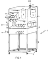
- the mobile apparatus 1 shown in figure 1 comprises a frame 2, which is supported on wheels 4 to be mobile between a position where the cleaning of equipment generally takes place (outside the working area of the dentist), and a position up to near the unit, on the dentist's chair or not.
- a cupboard 3 On top of the frame 2 there is a cupboard 3, in which the most important parts of the apparatus according to the invention are accommodated.
- a reservoir 4 for tap water, a steam source 5 and a compressor 6 or a connection for compressed air are shown schematically.
- the steam source 5 can be filled via supply 11 with distilled or demineralized water WD and the reservoir 4 can be filled with tap water W via supply 10, possibly by means of a self-tapping connection.
- Suitable hoses can be connected to the closable supplies 10 and 11, if refilling is necessary.
- a bowl 7 which can be closed fluid-tight with the help of a lockable transparent lid 8, which bowl is (here) provided on the rear wall with at least four connecting couplings A1, A2, A3 and A4, ... A n , to which conventional couplings on dentist's equipment can be placed.
- the number of connecting possibilities is adjusted to the amount of equipment which a dentist usually uses during a treatment.
- Three pneumatically driven angle pieces and one micro motor angle piece can be considered. Also medical, paramedical and dental equipment is possible.
- a water reservoir 4 is accommodated in the cupboard 3 which is to be filled with water from the water mains via closable supply opening 10 and line 12, and which can deliver water via discharge line 14 because of the action of the roller pump 100.
- Discharge line 14 branches into lines 15 and 16, which can be closed in a selective way by means of pinch valves 18, 19, respectively, or other valves acting on the outside of the hose, which are controlled by means of operating means not shown, which can be activated with suitable means on control panel 90.
- the difference between the line 15 and 16 is that about the line 15 a heating element 17 is placed which can be controlled in the desired way.
- the means necessary for that are also not shown, but they will be obvious for the expert.
- a detergent supply line 21 which receives a detergent means from the detergent reservoir 20 debouches into line 15.
- An adjustable meter 22 is located between the detergent line 21 and the water mains 15, and is also controlled by means not shown.
- a steam source 5 is accommodated on the right side in the cupboard 3 which can be filled via supply line 11 and closable line 13 with distilled or demineralized water.
- a discharge line for steam 25 extends from the steam source 5.
- the water line 16 and the water/detergent line 15 rejoin and then terminate at a multi-way valve 26, where the compressed air line 23 and the steam line 25 also end.
- a discharge line 28 which leads to the connecting coupling A1 and in which a valve 50 can be effective.
- the line 28 branches off into three lines 29.1, 29.2 and 29. 3, ...., 29.n.
- These lines 29.1, 29.2 29.3, ......, 29.n. are arranged in such a way with regard to one another that after having been connected to a connecting coupling A1 of the rear of the grip portion of a pneumatically driven angle piece 30, while sealed, they are aligned with passages or lumen in the angle piece.
- passages are shown in figure 3, and are arranged in the interior of the angle piece.
- Compressed air line 31, return air line 32, spray air line 33 and spray or cooling water line 34 can be distinguished.
- the return air line 32 is, moreover, aligned with passage 29.4 in connecting coupling A1, which passage connects into line 27 which leads to a receptacle 9, which in turn can be connected to a discharge line X.
- the connecting coupling A4 will therefore have to have a line connection to lumen 42 and to the lines 43 and 44, and furthermore a mechanically driven coupling for spindle 41, so as to allow the spindle to rotate during the cleaning and disinfecting for increasing the effectiveness of the cleaning/disinfecting.
- the apparatus 1 will be activated.
- the user can do this by operating the desired buttons on a control panel 90 by which a previously installed programme is possibly started up.
- An internal accumulator or battery or an external supply source, via an electric cable, can be used for the energy needed.
- the pump 100 is activated and will propel the water from the reservoir 4 through line 14.
- the valve 19 will be closed so that the water flows through line 15 and whilst flowing is heated by heating unit 17.
- Detergent is supplied by supply means 22.
- a detergent an all purpose cleaner which satisfies the requirements made above can be used and can be added in a concentration of e.g. 1 to 30.
- the detergent solution will then flow to the multi-way valve 26, which is adjusted such that the solution can flow directly through to passage 28.
- the detergent solution then enters the lines 31, 33 and 34 via the lines 29.1-29.3 and comes back via the angle piece head via the line 32.
- Surplus soap solution disappears between cracks and chinks in the angle piece head and is collected in the bowl 7, which can discharge to receptacle 9.
- the returned flow of detergent solution in which loosened lubricating oil and impurities are included is also lead to receptacle 9 via connection 29.4 and line 27, to be removed from there later or to be directly discharged
- the heating unit 17 is operated in such a way that in approximately 3 minutes the temperature of the water rises in from 20° to at least 60°C.
- the pump 100 can be controlled such that a pulsating flow of detergent solution is produced, with for example 10 seconds flow/10 seconds rest, and so on. Subsequently water is kept going for two minutes at that temperature with detergent solution dissolved therein. Therefore a start is made with cold washing, and gradually switching to warm washing.
- valve 18 After washing valve 18 is closed and valve 19 is opened so that water pumped by pump 100 will flow through line 16, and detergent free water arrives at multi-way valve 26 and is transferred to angle piece 30. During this flushing soap residue and impurities are discharged from angle piece 30.
- the multi-way valve 26 is automatically switched to form a connection between steam supply line 25 and the passage 28.
- steam is supplied under pressure to the angle piece and a wet disinfection by saturated steam injection takes place, as it were, without use being made of chemical means, and nontheless at a temperature which is lower than the temperature (121°C) at which sterilization normally takes place.
- the temperature of the introduced steam is, moreover, such that the flow of steam leaving the piece of equipment will have a temperature of at least approximately 100°C. Because the hollow spaces are pre-cleaned the steam is an effective disinfection means.
- the cross section of the return line is smaller than the cross section of the supply air line, in view of the fact that the steam is then forced to escape at the turbine in the angle piece head and can carry out its disinfecting action in all cracks and chinks. In doing so it is ensured that the number of revolutions is kept within the limits indicated by the manufacturer.
- the multi-way valve 26 After steaming the multi-way valve 26 is automatically switched over so as to connect the compressed air line 23 to the passage 28. Relatively cool compressed air is then forced out of the compressor 6 via a microfilter to the angle piece 30, for removing condensed steam and for cooling the angle piece so that the latter is soon ready for use again by the dentist.
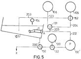
- washing can be carried out such that the angle pieces, after they have been mounted to the connecting couplings, are submerged in water.
- the bowl 7 will have to extend to well above the level of the connecting couplings, in the case of the apparatus of figure 1.
- FIG 5 the arrangement needed for this is shown in a schematic way.
- operation can take place as follows.
- bowl 107 the angle piece H is connected to connecting coupling A.
- the bowl 107 is filled with unheated water from reservoir 104, until the angle piece H is completely submerged.
- the pump 100' is operated to circulate water from the bowl 107 via line 200, two-way valve 150, line 201, pump 100', line 202 and angle piece H.
- detergent is supplied from detergent reservoir 120, via meter 122, to the water so that a detergent solution is present in the bowl 107.
- valve 150 is adjusted again and fresh water is drawn from reservoir 104 and circulated via angle pieces for flushing.
- the flush water can be discharged after a time (30 seconds) by yet again switching the valve 150.
- water could be supplied upstream (not shown) from angle piece H to achieve a maximum flushing effect, the valve 150 then connecting line 200 with discharge X.
- the bowl is refilled with water until the level above the angle piece.
- the steam source 105 is reactivated and the valve 152 is adjusted to connect the line 125 to line 204, and the valve 151 is set so that the line 204 connects with the line 205 and thus with line 202.
- the apparatus 1 of figure 1 is also suitable for cleaning with a view to removing biofilm and other impurities in hollow spaces, in particular in hoses.
- the hose is, on the one hand, connected to a connecting coupling S1-S n and, on the other hand, to the entrances R1-R n , possibly via a suitable adapter, and then subjected to the cleaning process described above.
- the washing phase can, alternatively, be omitted.
- a reservoir and supply lines for lubricating oil can be added on to the apparatus 3, which also open into multi-way valve 26, and/or decalcifying means. If only a few of the connecting couplings A1-An are being used, the connecting couplings not in use are closed by means of their pertaining valve 50.
- the processing time depends on the length of the hoses/lines, and the composition of the unit, which can be different for each unit.
- the operating means which can be activated by means of the operating of the control panel 90, can be programmable for expert personnel, preferably beforehand. In this way it is achieved that the process can take place automatically without there being the risk that due to a wrong action of the doctor or his assistant the cleaning/disinfecting process is carried out in an incorrect manner.
- the lines and most of the other passages in the apparatus 1 are made of metal or a synthetic (teflon) with a small biofilm forming capacity.
- the apparatus can further be provided with additional bypass lines (not shown) in order to permit flushing of the lines and passages for cleaning them.
Landscapes
- Health & Medical Sciences (AREA)
- General Health & Medical Sciences (AREA)
- Epidemiology (AREA)
- Life Sciences & Earth Sciences (AREA)
- Animal Behavior & Ethology (AREA)
- Public Health (AREA)
- Veterinary Medicine (AREA)
- Engineering & Computer Science (AREA)
- Mechanical Engineering (AREA)
- Dentistry (AREA)
- Oral & Maxillofacial Surgery (AREA)
- Dental Tools And Instruments Or Auxiliary Dental Instruments (AREA)
- Apparatus For Disinfection Or Sterilisation (AREA)
Applications Claiming Priority (2)
| Application Number | Priority Date | Filing Date | Title |
|---|---|---|---|
| NL9400677A NL9400677A (nl) | 1994-04-27 | 1994-04-27 | Werkwijze en inrichting voor het reinigen van medische, paramedische en tandheelkundige gereedschappen en -leidingen. |
| NL9400677 | 1994-04-27 |
Publications (2)
| Publication Number | Publication Date |
|---|---|
| EP0679406A1 true EP0679406A1 (de) | 1995-11-02 |
| EP0679406B1 EP0679406B1 (de) | 2002-07-31 |
Family
ID=19864121
Family Applications (1)
| Application Number | Title | Priority Date | Filing Date |
|---|---|---|---|
| EP95201022A Expired - Lifetime EP0679406B1 (de) | 1994-04-27 | 1995-04-24 | Verfahren und Einrichtung zum Reinigen von medizinischen, paramedizinischen und Zahnärztlichen Geräten und Leitungen |
Country Status (3)
| Country | Link |
|---|---|
| EP (1) | EP0679406B1 (de) |
| DE (1) | DE69527567D1 (de) |
| NL (1) | NL9400677A (de) |
Cited By (9)
| Publication number | Priority date | Publication date | Assignee | Title |
|---|---|---|---|---|
| US6245292B1 (en) * | 1994-12-28 | 2001-06-12 | Jostein Steien | Method for cleaning instruments within dental care and surgery |
| WO2005037330A1 (de) * | 2003-10-17 | 2005-04-28 | Meiko Maschinenbau Gmbh & Co. Kg | Verfahren zur kühlung von reinigungsgut in reinigungs- und desinfektionsautomaten |
| WO2010016066A1 (en) * | 2008-08-06 | 2010-02-11 | Naym 55 Dental Technologies Ltd. | Dental restoration conditioning apparatus and method |
| FR3022144A1 (fr) * | 2014-06-17 | 2015-12-18 | Dorel France Sa | Dispositif de rincage et de sterilisation d'un tuyau de tire-lait, et procede correspondant |
| CN106040683A (zh) * | 2016-07-29 | 2016-10-26 | 上海旭熠电子技术有限公司 | 光纤套管的自动清洗装置 |
| CN108940977A (zh) * | 2018-06-01 | 2018-12-07 | 宁波暄妍日化科技有限公司 | 一种基于轮架转轮冲洗技术的中药清洗装置 |
| IT201800010224A1 (it) | 2018-11-09 | 2020-05-09 | Steelco Spa | Apparato di pulizia e sanitizzazione |
| CN114632733A (zh) * | 2022-03-11 | 2022-06-17 | 中南大学湘雅医院 | 一种快插式牙椅负压接头清洗装置 |
| EP4151324A1 (de) * | 2021-09-16 | 2023-03-22 | Miele & Cie. KG | Aufnahmevorrichtung zum aufnehmen mindestens eines schlauchs für ein reinigungsgerät und reinigungsgerät |
Citations (6)
| Publication number | Priority date | Publication date | Assignee | Title |
|---|---|---|---|---|
| FR2098972A5 (de) * | 1970-07-31 | 1972-03-10 | Sp P Kon | |
| US4414037A (en) * | 1980-04-28 | 1983-11-08 | Max Friedheim | Steam jet cleaning and sterilizing system |
| GB2136911A (en) * | 1983-03-21 | 1984-09-26 | Electrolux Ab | Cleaning anaesthetic equipment |
| EP0300945A2 (de) * | 1987-07-24 | 1989-01-25 | Micro Mega S.A. | Automatischer Apparat für die Reinigung zahnärztlicher Handstücke |
| US5184571A (en) * | 1991-10-22 | 1993-02-09 | Avtron, Inc. | Automatically self-cleaning watering system |
| EP0580569A2 (de) * | 1992-07-22 | 1994-01-26 | Dentalwerk Bürmoos Gesellschaft M.B.H. | Vorrichtung zum Reinigen dentaler Handwerkzeuge |
-
1994
- 1994-04-27 NL NL9400677A patent/NL9400677A/nl active Search and Examination
-
1995
- 1995-04-24 EP EP95201022A patent/EP0679406B1/de not_active Expired - Lifetime
- 1995-04-24 DE DE69527567T patent/DE69527567D1/de not_active Expired - Lifetime
Patent Citations (6)
| Publication number | Priority date | Publication date | Assignee | Title |
|---|---|---|---|---|
| FR2098972A5 (de) * | 1970-07-31 | 1972-03-10 | Sp P Kon | |
| US4414037A (en) * | 1980-04-28 | 1983-11-08 | Max Friedheim | Steam jet cleaning and sterilizing system |
| GB2136911A (en) * | 1983-03-21 | 1984-09-26 | Electrolux Ab | Cleaning anaesthetic equipment |
| EP0300945A2 (de) * | 1987-07-24 | 1989-01-25 | Micro Mega S.A. | Automatischer Apparat für die Reinigung zahnärztlicher Handstücke |
| US5184571A (en) * | 1991-10-22 | 1993-02-09 | Avtron, Inc. | Automatically self-cleaning watering system |
| EP0580569A2 (de) * | 1992-07-22 | 1994-01-26 | Dentalwerk Bürmoos Gesellschaft M.B.H. | Vorrichtung zum Reinigen dentaler Handwerkzeuge |
Cited By (15)
| Publication number | Priority date | Publication date | Assignee | Title |
|---|---|---|---|---|
| US6245292B1 (en) * | 1994-12-28 | 2001-06-12 | Jostein Steien | Method for cleaning instruments within dental care and surgery |
| JP4713484B2 (ja) * | 2003-10-17 | 2011-06-29 | マイコ マシーネンバウ ゲゼルシャフト ミット ベシュレンクテル ハフツング ウント コンパニー コマンディートゲゼルシャフト | 自動洗浄滅菌機における洗浄済の物品の冷却方法 |
| WO2005037330A1 (de) * | 2003-10-17 | 2005-04-28 | Meiko Maschinenbau Gmbh & Co. Kg | Verfahren zur kühlung von reinigungsgut in reinigungs- und desinfektionsautomaten |
| EP1767226A1 (de) | 2003-10-17 | 2007-03-28 | MEIKO Maschinenbau GmbH & Co. KG | Vorrichtung zur reinigung und desinfektion mittels wasserdampfes von reinigungsgut sowie dessen kühlung |
| JP2007508084A (ja) * | 2003-10-17 | 2007-04-05 | マイコ マシーネンバウ ゲゼルシャフト ミット ベシュレンクテル ハフツング ウント コンパニー コマンディートゲゼルシャフト | 自動洗浄滅菌機における洗浄済の物品の冷却方法 |
| US8828286B2 (en) | 2008-08-06 | 2014-09-09 | Naym 55 Dental Technologies Ltd. | Dental restoration conditioning apparatus and method |
| WO2010016066A1 (en) * | 2008-08-06 | 2010-02-11 | Naym 55 Dental Technologies Ltd. | Dental restoration conditioning apparatus and method |
| FR3022144A1 (fr) * | 2014-06-17 | 2015-12-18 | Dorel France Sa | Dispositif de rincage et de sterilisation d'un tuyau de tire-lait, et procede correspondant |
| WO2015193397A1 (fr) * | 2014-06-17 | 2015-12-23 | Dorel France | Dispositif de rinçage et de stérilisation d'un tuyau de tire-lait, et procédé correspondant |
| CN106040683A (zh) * | 2016-07-29 | 2016-10-26 | 上海旭熠电子技术有限公司 | 光纤套管的自动清洗装置 |
| CN106040683B (zh) * | 2016-07-29 | 2018-06-08 | 上海旭熠电子技术有限公司 | 光纤套管的自动清洗装置 |
| CN108940977A (zh) * | 2018-06-01 | 2018-12-07 | 宁波暄妍日化科技有限公司 | 一种基于轮架转轮冲洗技术的中药清洗装置 |
| IT201800010224A1 (it) | 2018-11-09 | 2020-05-09 | Steelco Spa | Apparato di pulizia e sanitizzazione |
| EP4151324A1 (de) * | 2021-09-16 | 2023-03-22 | Miele & Cie. KG | Aufnahmevorrichtung zum aufnehmen mindestens eines schlauchs für ein reinigungsgerät und reinigungsgerät |
| CN114632733A (zh) * | 2022-03-11 | 2022-06-17 | 中南大学湘雅医院 | 一种快插式牙椅负压接头清洗装置 |
Also Published As
| Publication number | Publication date |
|---|---|
| NL9400677A (nl) | 1995-12-01 |
| EP0679406B1 (de) | 2002-07-31 |
| DE69527567D1 (de) | 2002-09-05 |
Similar Documents
| Publication | Publication Date | Title |
|---|---|---|
| JP3232090B2 (ja) | 医療機器の洗浄及び消毒 | |
| US6142170A (en) | Apparatus and method for dispensing disinfectant compositions for disinfecting water systems and lines | |
| US10758106B2 (en) | Reprocessing apparatus and a method of reprocessing a load in a reprocessing apparatus | |
| EP1945276B1 (de) | Endoskop-aufbereitungsgerät | |
| KR101177868B1 (ko) | 핸드피스 소독 멸균장치 | |
| EP0679406B1 (de) | Verfahren und Einrichtung zum Reinigen von medizinischen, paramedizinischen und Zahnärztlichen Geräten und Leitungen | |
| JP3515123B2 (ja) | 外科用器具を洗浄および/または殺菌するための装置 | |
| US20090000648A1 (en) | Method and device for preparing a medical instrument | |
| KR101121678B1 (ko) | 치과용 핸드피스 멸균기 | |
| EP0317521B2 (de) | Verfahren und Einrichtung zur Sterilisation des Zerstäubers und/oder der Luftzufuhr von medizinischen Instrumenten, insbesondere von zahnärztlichen Instrumenten | |
| JPH07299082A (ja) | 歯科診療装置 | |
| JP4010534B2 (ja) | 内視鏡洗浄消毒方法、その内視鏡洗浄消毒装置及び内視鏡洗浄消毒に用いる消毒液 | |
| JPH08323307A (ja) | 器具洗浄装置 | |
| US20230302170A1 (en) | System and method for cleaning and disinfecting a dental instrument | |
| CN214596079U (zh) | 一种口腔科用牙医器械快速清洁设备 | |
| US6368556B1 (en) | Apparatus for operational cleaning of dental handpieces | |
| JP3867838B2 (ja) | 管路洗浄方法及び装置、この管路洗浄装置を備えた診療装置 | |
| US6612838B2 (en) | Method for sterilizing conduits that convey fluid to medical instruments, especially dental instruments | |
| KR20110085346A (ko) | 핸드피스 소독장치 및 소독방법 | |
| JPH07275272A (ja) | 歯科用スピットン | |
| JP3725679B2 (ja) | 内視鏡洗滌消毒装置 | |
| US20190134682A1 (en) | Methods comprising to clean and/or lubricate fluid encompassing systems | |
| KR102297143B1 (ko) | 차염발생 내시경 소독장치 및 그 구동방법 | |
| JP2000126125A (ja) | 内視鏡洗滌消毒滅菌装置 | |
| JP4563597B2 (ja) | 治療施設内除菌システム |
Legal Events
| Date | Code | Title | Description |
|---|---|---|---|
| PUAI | Public reference made under article 153(3) epc to a published international application that has entered the european phase |
Free format text: ORIGINAL CODE: 0009012 |
|
| AK | Designated contracting states |
Kind code of ref document: A1 Designated state(s): DE DK FR GB NL SE |
|
| 17P | Request for examination filed |
Effective date: 19960402 |
|
| 17Q | First examination report despatched |
Effective date: 19981208 |
|
| GRAG | Despatch of communication of intention to grant |
Free format text: ORIGINAL CODE: EPIDOS AGRA |
|
| GRAG | Despatch of communication of intention to grant |
Free format text: ORIGINAL CODE: EPIDOS AGRA |
|
| GRAH | Despatch of communication of intention to grant a patent |
Free format text: ORIGINAL CODE: EPIDOS IGRA |
|
| GRAH | Despatch of communication of intention to grant a patent |
Free format text: ORIGINAL CODE: EPIDOS IGRA |
|
| GRAH | Despatch of communication of intention to grant a patent |
Free format text: ORIGINAL CODE: EPIDOS IGRA |
|
| GRAA | (expected) grant |
Free format text: ORIGINAL CODE: 0009210 |
|
| AK | Designated contracting states |
Kind code of ref document: B1 Designated state(s): DE DK FR GB NL SE |
|
| PG25 | Lapsed in a contracting state [announced via postgrant information from national office to epo] |
Ref country code: NL Free format text: LAPSE BECAUSE OF FAILURE TO SUBMIT A TRANSLATION OF THE DESCRIPTION OR TO PAY THE FEE WITHIN THE PRESCRIBED TIME-LIMIT Effective date: 20020731 Ref country code: FR Free format text: LAPSE BECAUSE OF FAILURE TO SUBMIT A TRANSLATION OF THE DESCRIPTION OR TO PAY THE FEE WITHIN THE PRESCRIBED TIME-LIMIT Effective date: 20020731 |
|
| REG | Reference to a national code |
Ref country code: GB Ref legal event code: FG4D |
|
| REF | Corresponds to: |
Ref document number: 69527567 Country of ref document: DE Date of ref document: 20020905 |
|
| PG25 | Lapsed in a contracting state [announced via postgrant information from national office to epo] |
Ref country code: SE Free format text: LAPSE BECAUSE OF FAILURE TO SUBMIT A TRANSLATION OF THE DESCRIPTION OR TO PAY THE FEE WITHIN THE PRESCRIBED TIME-LIMIT Effective date: 20021031 Ref country code: DK Free format text: LAPSE BECAUSE OF FAILURE TO SUBMIT A TRANSLATION OF THE DESCRIPTION OR TO PAY THE FEE WITHIN THE PRESCRIBED TIME-LIMIT Effective date: 20021031 |
|
| PG25 | Lapsed in a contracting state [announced via postgrant information from national office to epo] |
Ref country code: DE Free format text: LAPSE BECAUSE OF FAILURE TO SUBMIT A TRANSLATION OF THE DESCRIPTION OR TO PAY THE FEE WITHIN THE PRESCRIBED TIME-LIMIT Effective date: 20021101 |
|
| NLV1 | Nl: lapsed or annulled due to failure to fulfill the requirements of art. 29p and 29m of the patents act | ||
| PG25 | Lapsed in a contracting state [announced via postgrant information from national office to epo] |
Ref country code: GB Free format text: LAPSE BECAUSE OF NON-PAYMENT OF DUE FEES Effective date: 20030424 |
|
| PLBE | No opposition filed within time limit |
Free format text: ORIGINAL CODE: 0009261 |
|
| STAA | Information on the status of an ep patent application or granted ep patent |
Free format text: STATUS: NO OPPOSITION FILED WITHIN TIME LIMIT |
|
| 26N | No opposition filed |
Effective date: 20030506 |
|
| GBPC | Gb: european patent ceased through non-payment of renewal fee |