EP0679115B2 - Magnetisches rühren mittels wechselstrom für das kontinuierliche giessen vom metallen - Google Patents
Magnetisches rühren mittels wechselstrom für das kontinuierliche giessen vom metallen Download PDFInfo
- Publication number
- EP0679115B2 EP0679115B2 EP94904542A EP94904542A EP0679115B2 EP 0679115 B2 EP0679115 B2 EP 0679115B2 EP 94904542 A EP94904542 A EP 94904542A EP 94904542 A EP94904542 A EP 94904542A EP 0679115 B2 EP0679115 B2 EP 0679115B2
- Authority
- EP
- European Patent Office
- Prior art keywords
- stirring
- molten metal
- magnetic field
- meniscus
- rotating magnetic
- Prior art date
- Legal status (The legal status is an assumption and is not a legal conclusion. Google has not performed a legal analysis and makes no representation as to the accuracy of the status listed.)
- Expired - Lifetime
Links
- 229910052751 metal Inorganic materials 0.000 title claims abstract description 39
- 239000002184 metal Substances 0.000 title claims abstract description 39
- 239000003607 modifier Substances 0.000 title abstract description 8
- 238000009749 continuous casting Methods 0.000 title abstract description 6
- 238000003760 magnetic stirring Methods 0.000 title abstract description 6
- 150000002739 metals Chemical class 0.000 title abstract description 4
- 238000003756 stirring Methods 0.000 claims abstract description 92
- 230000005499 meniscus Effects 0.000 claims abstract description 59
- 230000033001 locomotion Effects 0.000 claims abstract description 30
- 238000000034 method Methods 0.000 claims abstract description 26
- 238000005266 casting Methods 0.000 claims abstract description 23
- 230000006698 induction Effects 0.000 claims abstract description 18
- 230000008569 process Effects 0.000 claims description 11
- 229910000831 Steel Inorganic materials 0.000 claims description 9
- 239000010959 steel Substances 0.000 claims description 9
- 230000000694 effects Effects 0.000 claims description 4
- 238000011144 upstream manufacturing Methods 0.000 claims description 2
- 230000001939 inductive effect Effects 0.000 claims 1
- 230000005405 multipole Effects 0.000 claims 1
- 229910001338 liquidmetal Inorganic materials 0.000 description 16
- 230000009471 action Effects 0.000 description 12
- 230000004907 flux Effects 0.000 description 10
- 229910045601 alloy Inorganic materials 0.000 description 4
- 239000000956 alloy Substances 0.000 description 4
- 230000000875 corresponding effect Effects 0.000 description 4
- 239000000843 powder Substances 0.000 description 4
- 238000007711 solidification Methods 0.000 description 4
- 230000008023 solidification Effects 0.000 description 4
- 230000007547 defect Effects 0.000 description 3
- 238000009826 distribution Methods 0.000 description 3
- 239000007788 liquid Substances 0.000 description 3
- 230000001276 controlling effect Effects 0.000 description 2
- 230000003247 decreasing effect Effects 0.000 description 2
- 238000010586 diagram Methods 0.000 description 2
- 230000002708 enhancing effect Effects 0.000 description 2
- 239000000463 material Substances 0.000 description 2
- 230000007935 neutral effect Effects 0.000 description 2
- 238000004886 process control Methods 0.000 description 2
- 206010001497 Agitation Diseases 0.000 description 1
- 229910000532 Deoxidized steel Inorganic materials 0.000 description 1
- 229910000655 Killed steel Inorganic materials 0.000 description 1
- 229910006639 Si—Mn Inorganic materials 0.000 description 1
- 230000001133 acceleration Effects 0.000 description 1
- 230000006978 adaptation Effects 0.000 description 1
- 238000013019 agitation Methods 0.000 description 1
- 238000013459 approach Methods 0.000 description 1
- 230000009286 beneficial effect Effects 0.000 description 1
- 229910052799 carbon Inorganic materials 0.000 description 1
- 239000000919 ceramic Substances 0.000 description 1
- 230000008859 change Effects 0.000 description 1
- 230000002596 correlated effect Effects 0.000 description 1
- 230000006866 deterioration Effects 0.000 description 1
- 230000003628 erosive effect Effects 0.000 description 1
- 229910000939 field's metal Inorganic materials 0.000 description 1
- -1 for example Substances 0.000 description 1
- 230000005484 gravity Effects 0.000 description 1
- 238000009533 lab test Methods 0.000 description 1
- 238000005461 lubrication Methods 0.000 description 1
- QSHDDOUJBYECFT-UHFFFAOYSA-N mercury Chemical compound [Hg] QSHDDOUJBYECFT-UHFFFAOYSA-N 0.000 description 1
- 229910052753 mercury Inorganic materials 0.000 description 1
- 230000010355 oscillation Effects 0.000 description 1
- 230000001151 other effect Effects 0.000 description 1
- 230000009467 reduction Effects 0.000 description 1
- 239000002893 slag Substances 0.000 description 1
- 239000000126 substance Substances 0.000 description 1
Images


Classifications
-
- B—PERFORMING OPERATIONS; TRANSPORTING
- B22—CASTING; POWDER METALLURGY
- B22D—CASTING OF METALS; CASTING OF OTHER SUBSTANCES BY THE SAME PROCESSES OR DEVICES
- B22D11/00—Continuous casting of metals, i.e. casting in indefinite lengths
- B22D11/10—Supplying or treating molten metal
- B22D11/11—Treating the molten metal
- B22D11/114—Treating the molten metal by using agitating or vibrating means
- B22D11/115—Treating the molten metal by using agitating or vibrating means by using magnetic fields
Definitions
- the present invention relates to the continuous casting of metals and alloys, for example, steel.
- Electromagnetic stirring of liquid steel within the mold is broadly employed in continuous casting mainly to improve quality of the strand surface/sub-surface and solidification structure (i.e., structure refinement, soundness and chemical homogeneity).
- Japanese Patent Publication No. 58-23554 describes a method of decreasing the intensity of stirring in the meniscus region by means of an induction coil arranged on the mold adjacent to that region and providing rotating stirring motion opposite to that induced by the main EMS coil arranged below.
- the main drawback of this method is that the induction coil adjacent to the meniscus region provides only a deceleration of the stirring velocity produced by EMS. In the case when an intensive stirring action within the meniscus region is required, this method would need to relinquish its decelerating action by de-energizing the coil. The coil is not intended to enhance stirring action if the need of such enhancement arises, for the reasons discussed above.
- the depth of meniscus depression h approaches zero when the angular stirring velocity at the meniscus caused by EMS is equalized by counter-stirring angular velocity produced by a braking induction coil.
- AT-PS 189751 discloses electromagnetic stirring in an open stream process using two electromagnetic coil arrangements are above the other operated in unison.
- EP-A-0 096 077 discloses a plurality of electromagnetic agitations arranged in a horizontal direction along a wall of a mold to accelerate or decelerate the circulatory flow along the flow direction but does not provide a second magnetic field at a location upstream of the stirring by a first rotating magnetic field.
- DE-A-3 819 492 discloses two stirrers, one upon the other, and discloses operating one or both of the stirrers in a casting method.
- EP-A-0 080326 discloses one rotational field only together with an axial field.
- JP-A-59 89649 discloses a submerged nozzle process in which an upper coil produces a field rotating in the opposite direction to that produced by a lower coil to provide a braking effect at the surface of the molder metal.
- An electromagnetic volume force will be produced in either of two situations, firstly, when an A.C. rotating magnetic field interacts with liquid metal which is in the state of complete rest, the metal will be set into a motion with a velocity lower than that of the A.C. field; and, secondly, when a stationary, i.e. D.C. magnetic field, interacts with liquid metal already in motion.
- the present invention thus provides an improved method of controlling electromagnetic stirring intensity within a continuous casting mold. This method provides both the flexibility of adaptation of stirring conditions to the casting processes and the accuracy of stirring control which were lacking by prior art.
- the present invention may be performed using an apparatus which includes an electromagnetic A.C. coil similar to but smaller than that of a main electromagnetic stirrer installed downstream and arranged around the mold in the meniscus area.
- This device is in essence another induction stirrer, similar to the main stirrer which is arranged axially symmetrical around the mold and farther down from the meniscus.
- the coil in the upper part of the mold is suitable for counterbalancing and equalizing, or enhancing, depending on specific objectives, the stirring motion in the adjacent volume of liquid metal, whose motion is originated by the main stirrer. Therefore, the working function of this stirrer is to modify the pattern and/or intensity of the stirring induced by the main stirrer and henceforth the device performing that function will be called A.C. magnetic stirring modifier or A.C. MSM.
- the action of the A.C. MSM is typically contained within the upper portion of molten metal pool, comprising approximately 10 to 15 percent of its volume confined by the mold.
- both the A.C. MSM and M-EMS operate at a common frequency determined by the parameters of the mold.
- the current supplied to both sets of the coils can be of the same variable value or it can be controlled separately.
- the invention is broadly applicable to all electroconductive materials, i.e. metals and alloys, which can be electromagnetically stirred and where control of stirring intensity is required within some region or regions without interference with stirring within other regions of the liquid pool.
- the invention is applicable to a wide variety of spacial orientation of a vessel containing the molten method.
- a casting mold may be arranged vertically, inclined or horizontally.
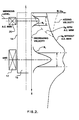
- Figure 1 is a schematic depiction of an arrangement of an A.C. MSM and an EMS within a mold housing assembly of a continuous casting machine 10 .
- Figure 5 is a more detailed depiction of the mechanical elements of the mold assembly.
- a series of induction coils 12, is arranged equally spaced around the periphery of a vertical casting mold 14, at its lower portion to comprise an A.C. electromagnetic stirrer (EMS).
- EMS electromagnetic stirrer
- a casting ceramic tube 18 is axially located with respect to the strand of molten metal 16, if the apparatus is to be used for casting with a submerged entrance nozzle instead of the open pouring method.
- A.C. MSM induction coils 20, are equally spaced around the vertical mold 14, adjacent to a free upper surface or meniscus 22 of the strand of molten metal 16.
- the EMS coils 12 are designed to induce a strong rotational flow of molten metal in the strand of molten metal 16 within the mold 14.
- a maximum value of rotational velocity is attained within and about the region of molten metal defined by a characteristic length of stirrer L which corresponds to a magnetic flux density B distribution along stirring axis.
- a typical magnetic flux density distribution for the two sets of induction coils 12 and 20 are shown in Figure 2.
- the value of the maximum stirring velocity within and about the active stirring zone L and the rate of its axial attenuation within the metal 16 determine the stirring velocity at the meniscus area 22 in the absence of other effects.
- the stirring velocity value and its lengthwise axial range depend on the stirrer length L, the radius of the stirred pool R, and the roughness of the solidification interface with liquid metal. Accordingly, it is difficult to quantitatively and accurately predict the stirring velocity at the meniscus, based upon the design and operating parameters of the EMS coils 12 and the distance from EMS neutral axis to the meniscus.
- the stirring velocity at the meniscus generally is about 0.5 to 0.7 (about 50 to 70 percent) of maximum stirring velocity value while the EMS coils 12 are located at a lowest position with respect to the meniscus. Therefore, a substantial stirring action can be expected at the meniscus area produced by the EMS coils even if the latter is located at the farthest possible distance from the meniscus. Meniscus depression and, more generally, turbulence at this location manifest themselves as a result of this stirring action.
- the meniscus depression depth is strongly correlated to the angular stirring velocity at the meniscus.
- the meniscus stirring velocity and depression are proportional to the current supplied to the EMS coils 12, as shown schematically in Figure 3.
- the meniscus depression for industrial systems can range from approximately 6 to 27 mm, for example.
- the induction coils 20 of A.C. MSM are energized, to induce a stirring action within the liquid metal at the meniscus opposite to that caused by the EMS coils 12. All the previous considerations with respect to a rotary movement of liquid metal are applicable to the stirring produced by the A.C. MSM coils 20.
- the A.C. MSM coils 20 are substantially smaller and require less power for their operation than the EMS coils 12 due to a much less stirring velocity expected for them to produce to counteract the rotational motion at the meniscus induced by the EMS coils 12.
- the A.C. MSM coils 20 are energized from a power supply common with the EMS coils 12, as shown by single line diagrams in Figure 4.
- Schemes I and II appearing in Figure 4 show the A.C. MSM and EMS coils 20 and 12 respectively connected in series and, therefore, operating at the time same current and frequency supplied from a common power source.
- the coil connections presented in Scheme I provide for unidirectional rotating magnetic fields produced by both the EMS and A.C. MSM coils. This mode of operation is employed for enhancing the stirring motion at the meniscus area by the A.C. MSM coils 20 when performing the process of the present invention with the illustrated apparatus.
- the coil connections presented in Scheme II provide for counter-rotating magnetic fields and cause counter-rotating liquid metal motions in the areas corresponding to the EMS and A.C. MSM coils.
- the current level supplied to the A.C. MSM coils 20 may have an independent control from that of the EMS coils 12, as shown by Scheme III in Figure 4. This arrangement allows for independent control of stirring actions of either of the EMS or the A.C. MSM coils regardless of the directional pattem of stirring, namely unirotational or counter-rotational.
- the line OA corresponds to the meniscus depression caused by the stirring induced by EMS coils 12 without being opposed or added by A.C. MSM stirring.
- the line OD represents meniscus depression associated with isolated stirring action induced by the A.C. MSM coils 20.
- the meniscus depression In order to equalize the stirring velocities caused by the EMS and A.C. MSM coils, the meniscus depression must be of the same value in either of the situations. For example, if the meniscus depression caused by EMS stirring corresponds to the level A, then counter-rotational stirring provided by A.C. MSM stirring should have corresponding meniscus depression, i.e. level D.
- the line OC is the resultant of two opposite stirring actions produced respectively by the EMS and AC MSM coils and equalized at the meniscus.
- the line AB represents the resultant of two unidirectional stirring actions.
- the range of stirring enhancement expressed through the meniscus depression can be adjusted in accordance with the casting practice requirements, so that the stirring intensity of EMS is fully utilized.
Landscapes
- Engineering & Computer Science (AREA)
- Mechanical Engineering (AREA)
- Continuous Casting (AREA)
- Furnace Details (AREA)
- Mixers With Rotating Receptacles And Mixers With Vibration Mechanisms (AREA)
Claims (6)
- Verfahren zum kontinuierlichen Gießen von Knüppeln und Vorblöcken aus Metallschmelze mittels einer Vorrichtung, die eine Gießform aufweist, in die Metallschmelze durch einen Vorgang des offenen Gießens der Metallschmelze eingeführt wird, und Durchführung eines Induktionsrührens in der Metallschmelze in der Form, wobei das Induktionsrührverfahren umfasst:elektromagnetisches Induzieren des Rührens von geschmolzenem Metall mit einer Intensität, die normalerweise zu einer Turbulenz in dem geschmolzenen Metall einschließlich seiner freien Oberfläche führt, durch Anlegen eines ersten rotierenden Magnetfeldes an das geschmolzene Metall, undAnlegen eines zweiten rotierenden Magnetfeldes, das von einer von der das erste Magnetfeld liefernden Quelle getrennten Quelle und an einer Stelle stromaufwärts des Rührens erzeugt wird, wobei das zweite rotierende Magnetfeld in derselben Richtung rotiert wie die Rotationsrichtung des ersten Feldes, um die Rührbewegung im Bereich der freien Oberfläche zu verstärken, aber ein Drehmoment auf das geschmolzene Metall ausübt, welches niedriger ist als das von dem ersten Feld ausgeübte Drehmoment.
- Verfahren nach Anspruch 1, bei dem das zweite rotierende Magnetfeld durch einen Satz von Induktionsspulen geliefert wird, die nahe der freien Oberfläche der Metallschmelze angeordnet sind.
- Verfahren nach Anspruch 1 oder 2, bei dem das zweite rotierende Magnetfeld von einem Satz von Induktionsspulen erzeugt wird, die von einem Wechselstrom beaufschlagt sind, der von einer Stromquelle geliefert wird, die unabhängig ist von einer Stromquelle für einen das erste rotierende Magnetfeld erzeugenden Satz von Induktionsspulen.
- Verfahren nach Anspruch 3, bei dem die Sätze von Induktionsspulen Spulen mit Multiphasen- und Multipol-Anordnung sind, die in Umfangsrichtung beabstandet um die Form herum angeordnet sind, um die jeweiligen rotierenden Magnetfelder zu erzeugen.
- Verfahren nach einem der Ansprüche 1 bis 4, bei dem das zweite rotierende Magnetfeld dazu dient, eine Rührbewegung in dem Meniskusbereich zu bewirken, die ausreicht, um die von dem ersten rotierenden Magnetfeld in dem Meniskusbereich bewirkte Rührbewegung auf ein Niveau anzuheben, das bei oder nahe dem Niveau der Rührbewegung liegt, die von dem ersten rotierenden Magnetfeld an seiner stromabwärts liegenden Aufbringungsstelle erzeugt wird.
- Verfahren nach einem der Ansprüche 1 bis 5, bei dem die Metallschmelze Stahl ist.
Applications Claiming Priority (3)
| Application Number | Priority Date | Filing Date | Title |
|---|---|---|---|
| US506293A | 1993-01-15 | 1993-01-15 | |
| US5062 | 1993-01-15 | ||
| PCT/CA1994/000018 WO1994015739A1 (en) | 1993-01-15 | 1994-01-14 | A.c. magnetic stirring modifier for continuous casting of metals |
Publications (3)
| Publication Number | Publication Date |
|---|---|
| EP0679115A1 EP0679115A1 (de) | 1995-11-02 |
| EP0679115B1 EP0679115B1 (de) | 1997-06-25 |
| EP0679115B2 true EP0679115B2 (de) | 2004-09-15 |
Family
ID=21713965
Family Applications (1)
| Application Number | Title | Priority Date | Filing Date |
|---|---|---|---|
| EP94904542A Expired - Lifetime EP0679115B2 (de) | 1993-01-15 | 1994-01-14 | Magnetisches rühren mittels wechselstrom für das kontinuierliche giessen vom metallen |
Country Status (6)
| Country | Link |
|---|---|
| EP (1) | EP0679115B2 (de) |
| AT (1) | ATE154767T1 (de) |
| CA (1) | CA2153995C (de) |
| DE (1) | DE69403950T3 (de) |
| ES (1) | ES2106501T5 (de) |
| WO (1) | WO1994015739A1 (de) |
Families Citing this family (6)
| Publication number | Priority date | Publication date | Assignee | Title |
|---|---|---|---|---|
| IT1288900B1 (it) * | 1996-05-13 | 1998-09-25 | Danieli Off Mecc | Procedimento di colata continua con campo magnetico pulsante e relativo dispositivo |
| DE102005042370A1 (de) | 2005-09-07 | 2007-03-15 | Sms Demag Ag | Bauteil für eine Stranggießkokille und Verfahren zur Herstellung des Bauteils |
| US20090242165A1 (en) * | 2008-03-25 | 2009-10-01 | Beitelman Leonid S | Modulated electromagnetic stirring of metals at advanced stage of solidification |
| CN103170606B (zh) * | 2011-12-23 | 2015-08-26 | 北京有色金属研究总院 | 双重强制均匀化制备金属浆料的装置及其加工成形方法 |
| CN108971460A (zh) * | 2018-08-22 | 2018-12-11 | 上海大学 | 一种脉冲耦合电磁场细化金属凝固组织的方法及装置 |
| CN115430828B (zh) * | 2022-09-22 | 2024-07-23 | 济南海圣机电科技有限公司 | 一种浇注机铁水定量定速浇注控制方法 |
Citations (3)
| Publication number | Priority date | Publication date | Assignee | Title |
|---|---|---|---|---|
| AT184313B (de) † | 1953-07-30 | 1956-01-10 | Boehler & Co Ag Geb | Verfahren und Vorrichtung zum kontinuierlichen Gießen, insbesondere von schwer schmelzbaren Metallen |
| DE1583601A1 (de) † | 1967-07-05 | 1970-09-17 | Demag Elektrometallurgie Gmbh | Verfahren und Vorrichtung zum Kuehlen eines schmelzfluessigen Metallstranges |
| JPS5989649U (ja) † | 1982-12-04 | 1984-06-18 | 三菱重工業株式会社 | 連続鋳造用電磁撹拌装置 |
Family Cites Families (6)
| Publication number | Priority date | Publication date | Assignee | Title |
|---|---|---|---|---|
| AT189751B (de) * | 1952-08-27 | 1957-05-10 | Verfahren zum Gießen, insbesondere zum Stranggießen von Metallen | |
| FR2391015A1 (fr) * | 1977-05-18 | 1978-12-15 | Siderurgie Fse Inst Rech | Perfectionnement au procede de coulee continue centrifuge de produits metalliques et dispositif de mise en oeuvre |
| EP0080326A1 (de) * | 1981-11-20 | 1983-06-01 | British Steel Corporation | Einrichtung für das Stranggiessen von Stahl |
| JPS58100955A (ja) * | 1981-12-11 | 1983-06-15 | Kawasaki Steel Corp | 連続鋳造鋳型内溶鋼の撹拌方法およびその装置 |
| DE3819492A1 (de) * | 1988-06-08 | 1989-12-14 | Voest Alpine Ind Anlagen | Knueppel- bzw. vorblock-stranggiesskokille |
| US4933005A (en) * | 1989-08-21 | 1990-06-12 | Mulcahy Joseph A | Magnetic control of molten metal systems |
-
1994
- 1994-01-14 CA CA002153995A patent/CA2153995C/en not_active Expired - Fee Related
- 1994-01-14 AT AT94904542T patent/ATE154767T1/de not_active IP Right Cessation
- 1994-01-14 WO PCT/CA1994/000018 patent/WO1994015739A1/en not_active Ceased
- 1994-01-14 ES ES94904542T patent/ES2106501T5/es not_active Expired - Lifetime
- 1994-01-14 DE DE69403950T patent/DE69403950T3/de not_active Expired - Lifetime
- 1994-01-14 EP EP94904542A patent/EP0679115B2/de not_active Expired - Lifetime
Patent Citations (3)
| Publication number | Priority date | Publication date | Assignee | Title |
|---|---|---|---|---|
| AT184313B (de) † | 1953-07-30 | 1956-01-10 | Boehler & Co Ag Geb | Verfahren und Vorrichtung zum kontinuierlichen Gießen, insbesondere von schwer schmelzbaren Metallen |
| DE1583601A1 (de) † | 1967-07-05 | 1970-09-17 | Demag Elektrometallurgie Gmbh | Verfahren und Vorrichtung zum Kuehlen eines schmelzfluessigen Metallstranges |
| JPS5989649U (ja) † | 1982-12-04 | 1984-06-18 | 三菱重工業株式会社 | 連続鋳造用電磁撹拌装置 |
Also Published As
| Publication number | Publication date |
|---|---|
| CA2153995C (en) | 2000-11-07 |
| WO1994015739A1 (en) | 1994-07-21 |
| EP0679115B1 (de) | 1997-06-25 |
| EP0679115A1 (de) | 1995-11-02 |
| ES2106501T3 (es) | 1997-11-01 |
| DE69403950T2 (de) | 1997-12-11 |
| CA2153995A1 (en) | 1994-07-21 |
| ATE154767T1 (de) | 1997-07-15 |
| ES2106501T5 (es) | 2005-03-01 |
| DE69403950D1 (de) | 1997-07-31 |
| DE69403950T3 (de) | 2005-03-10 |
Similar Documents
| Publication | Publication Date | Title |
|---|---|---|
| US5699850A (en) | Method and apparatus for control of stirring in continuous casting of metals | |
| Beitelman | Effect of mold EMS design on billet casting productivity and product quality | |
| EP2038081B1 (de) | Verfahren und vorrichtung zur flusssteuerung von stahlschmelze in einer form | |
| US20080164004A1 (en) | Method and system of electromagnetic stirring for continuous casting of medium and high carbon steels | |
| RU2266798C2 (ru) | Способ и устройство для непрерывной разливки металлов в кристаллизатор | |
| EP1021262B1 (de) | Verfahren und vorrichtung zur kontrolle des metallflusses während des stranggiessens unter verwendung elektromagnetischer felder | |
| EP0401504A2 (de) | Verfahren und Vorrichtung zum Stranggiessen | |
| AU2003286222B2 (en) | Method and device for controlling flows in a continuous slab casting ingot mould | |
| CA2074866A1 (en) | Process for ingot casting employing a magnetic field for reducing macrosegregation and associated apparatus and ingot | |
| JP3904226B2 (ja) | 電磁場を用いる金属垂直連続鋳造方法とその実施のための鋳造設備 | |
| Kunstreich | Electromagnetic stirring for continuous casting | |
| EP0550785B1 (de) | Verfahren zum Stranggiessen | |
| EP0679115B2 (de) | Magnetisches rühren mittels wechselstrom für das kontinuierliche giessen vom metallen | |
| JPH01150450A (ja) | 流し込みストランドの非凝固部分の取扱い方法及び装置 | |
| JPH0523804A (ja) | 鋼のスラブ用鋳片の製造方法 | |
| Garnier | The Clifford Paterson Lecture, 1992 Magentohydrodynamics in material processing | |
| CA1334337C (en) | Magnetic streamlining and flow control in tundishes | |
| EP0531851A1 (de) | Verfahren und Vorrichtung zum magnetischen Rühren der Schmelze in einer Zweirollengiessanlage | |
| US7237597B2 (en) | Method and device for continuous casting of metals in a mold | |
| JP3491099B2 (ja) | 静磁場を用いた鋼の連続鋳造方法 | |
| JPH0238303B2 (de) | ||
| KR960003711B1 (ko) | 연속 슬랩 주조방법 | |
| Sjoden et al. | Use of electromagnetic equipment for slab and thin slab steel continuous caster | |
| JPH0819840A (ja) | 連続鋳造方法 | |
| WO1993004801A1 (en) | Method and apparatus for the electromagnetic stirring of molten metals in a wheel caster |
Legal Events
| Date | Code | Title | Description |
|---|---|---|---|
| PUAI | Public reference made under article 153(3) epc to a published international application that has entered the european phase |
Free format text: ORIGINAL CODE: 0009012 |
|
| 17P | Request for examination filed |
Effective date: 19950801 |
|
| AK | Designated contracting states |
Kind code of ref document: A1 Designated state(s): AT BE CH DE DK ES FR GB GR IE IT LI LU MC NL PT SE |
|
| GRAG | Despatch of communication of intention to grant |
Free format text: ORIGINAL CODE: EPIDOS AGRA |
|
| 17Q | First examination report despatched |
Effective date: 19960701 |
|
| GRAH | Despatch of communication of intention to grant a patent |
Free format text: ORIGINAL CODE: EPIDOS IGRA |
|
| GRAH | Despatch of communication of intention to grant a patent |
Free format text: ORIGINAL CODE: EPIDOS IGRA |
|
| GRAA | (expected) grant |
Free format text: ORIGINAL CODE: 0009210 |
|
| AK | Designated contracting states |
Kind code of ref document: B1 Designated state(s): AT BE CH DE DK ES FR GB GR IE IT LI LU MC NL PT SE |
|
| PG25 | Lapsed in a contracting state [announced via postgrant information from national office to epo] |
Ref country code: NL Free format text: LAPSE BECAUSE OF FAILURE TO SUBMIT A TRANSLATION OF THE DESCRIPTION OR TO PAY THE FEE WITHIN THE PRESCRIBED TIME-LIMIT Effective date: 19970625 Ref country code: LI Effective date: 19970625 Ref country code: GR Free format text: LAPSE BECAUSE OF FAILURE TO SUBMIT A TRANSLATION OF THE DESCRIPTION OR TO PAY THE FEE WITHIN THE PRESCRIBED TIME-LIMIT Effective date: 19970625 Ref country code: DK Effective date: 19970625 Ref country code: CH Effective date: 19970625 Ref country code: BE Effective date: 19970625 Ref country code: AT Effective date: 19970625 |
|
| REF | Corresponds to: |
Ref document number: 154767 Country of ref document: AT Date of ref document: 19970715 Kind code of ref document: T |
|
| REG | Reference to a national code |
Ref country code: CH Ref legal event code: EP |
|
| ET | Fr: translation filed | ||
| REF | Corresponds to: |
Ref document number: 69403950 Country of ref document: DE Date of ref document: 19970731 |
|
| ITF | It: translation for a ep patent filed | ||
| PG25 | Lapsed in a contracting state [announced via postgrant information from national office to epo] |
Ref country code: SE Effective date: 19970925 Ref country code: PT Effective date: 19970925 |
|
| REG | Reference to a national code |
Ref country code: ES Ref legal event code: FG2A Ref document number: 2106501 Country of ref document: ES Kind code of ref document: T3 |
|
| NLV1 | Nl: lapsed or annulled due to failure to fulfill the requirements of art. 29p and 29m of the patents act | ||
| REG | Reference to a national code |
Ref country code: CH Ref legal event code: PL |
|
| PG25 | Lapsed in a contracting state [announced via postgrant information from national office to epo] |
Ref country code: LU Free format text: LAPSE BECAUSE OF NON-PAYMENT OF DUE FEES Effective date: 19980114 Ref country code: IE Free format text: LAPSE BECAUSE OF NON-PAYMENT OF DUE FEES Effective date: 19980114 |
|
| PLBQ | Unpublished change to opponent data |
Free format text: ORIGINAL CODE: EPIDOS OPPO |
|
| PLBI | Opposition filed |
Free format text: ORIGINAL CODE: 0009260 |
|
| 26 | Opposition filed |
Opponent name: CONCAST STANDARD AG Effective date: 19980318 Opponent name: ASEA BROWN BOVERI AB Effective date: 19980320 |
|
| PLBF | Reply of patent proprietor to notice(s) of opposition |
Free format text: ORIGINAL CODE: EPIDOS OBSO |
|
| PG25 | Lapsed in a contracting state [announced via postgrant information from national office to epo] |
Ref country code: MC Free format text: LAPSE BECAUSE OF NON-PAYMENT OF DUE FEES Effective date: 19980731 |
|
| PLBF | Reply of patent proprietor to notice(s) of opposition |
Free format text: ORIGINAL CODE: EPIDOS OBSO |
|
| PLBF | Reply of patent proprietor to notice(s) of opposition |
Free format text: ORIGINAL CODE: EPIDOS OBSO |
|
| PLBF | Reply of patent proprietor to notice(s) of opposition |
Free format text: ORIGINAL CODE: EPIDOS OBSO |
|
| REG | Reference to a national code |
Ref country code: GB Ref legal event code: IF02 |
|
| PLAW | Interlocutory decision in opposition |
Free format text: ORIGINAL CODE: EPIDOS IDOP |
|
| APAC | Appeal dossier modified |
Free format text: ORIGINAL CODE: EPIDOS NOAPO |
|
| APAC | Appeal dossier modified |
Free format text: ORIGINAL CODE: EPIDOS NOAPO |
|
| REG | Reference to a national code |
Ref country code: FR Ref legal event code: TP |
|
| APBU | Appeal procedure closed |
Free format text: ORIGINAL CODE: EPIDOSNNOA9O |
|
| REG | Reference to a national code |
Ref country code: ES Ref legal event code: PC2A |
|
| PUAH | Patent maintained in amended form |
Free format text: ORIGINAL CODE: 0009272 |
|
| STAA | Information on the status of an ep patent application or granted ep patent |
Free format text: STATUS: PATENT MAINTAINED AS AMENDED |
|
| RAP2 | Party data changed (patent owner data changed or rights of a patent transferred) |
Owner name: ABB INC. |
|
| 27A | Patent maintained in amended form |
Effective date: 20040915 |
|
| AK | Designated contracting states |
Kind code of ref document: B2 Designated state(s): AT BE CH DE DK ES FR GB GR IE IT LI LU MC NL PT SE |
|
| APAA | Appeal reference recorded |
Free format text: ORIGINAL CODE: EPIDOS REFN |
|
| REG | Reference to a national code |
Ref country code: ES Ref legal event code: DC2A Date of ref document: 20040928 Kind code of ref document: T5 |
|
| ET3 | Fr: translation filed ** decision concerning opposition | ||
| APAH | Appeal reference modified |
Free format text: ORIGINAL CODE: EPIDOSCREFNO |
|
| PGFP | Annual fee paid to national office [announced via postgrant information from national office to epo] |
Ref country code: FR Payment date: 20120227 Year of fee payment: 19 |
|
| PGFP | Annual fee paid to national office [announced via postgrant information from national office to epo] |
Ref country code: DE Payment date: 20120221 Year of fee payment: 19 |
|
| PGFP | Annual fee paid to national office [announced via postgrant information from national office to epo] |
Ref country code: GB Payment date: 20120221 Year of fee payment: 19 Ref country code: IT Payment date: 20120227 Year of fee payment: 19 |
|
| PGFP | Annual fee paid to national office [announced via postgrant information from national office to epo] |
Ref country code: ES Payment date: 20120222 Year of fee payment: 19 |
|
| GBPC | Gb: european patent ceased through non-payment of renewal fee |
Effective date: 20130114 |
|
| REG | Reference to a national code |
Ref country code: FR Ref legal event code: ST Effective date: 20130930 |
|
| PG25 | Lapsed in a contracting state [announced via postgrant information from national office to epo] |
Ref country code: DE Free format text: LAPSE BECAUSE OF NON-PAYMENT OF DUE FEES Effective date: 20130801 |
|
| REG | Reference to a national code |
Ref country code: DE Ref legal event code: R119 Ref document number: 69403950 Country of ref document: DE Effective date: 20130801 |
|
| PG25 | Lapsed in a contracting state [announced via postgrant information from national office to epo] |
Ref country code: FR Free format text: LAPSE BECAUSE OF NON-PAYMENT OF DUE FEES Effective date: 20130131 Ref country code: GB Free format text: LAPSE BECAUSE OF NON-PAYMENT OF DUE FEES Effective date: 20130114 |
|
| PG25 | Lapsed in a contracting state [announced via postgrant information from national office to epo] |
Ref country code: IT Free format text: LAPSE BECAUSE OF NON-PAYMENT OF DUE FEES Effective date: 20130114 |
|
| REG | Reference to a national code |
Ref country code: ES Ref legal event code: FD2A Effective date: 20140324 |
|
| PG25 | Lapsed in a contracting state [announced via postgrant information from national office to epo] |
Ref country code: ES Free format text: LAPSE BECAUSE OF NON-PAYMENT OF DUE FEES Effective date: 20130115 |