EP0678952B1 - Sectionneur pour un appareillage de commutation blindé métallique à haute tension et à isolement gazeux - Google Patents
Sectionneur pour un appareillage de commutation blindé métallique à haute tension et à isolement gazeux Download PDFInfo
- Publication number
- EP0678952B1 EP0678952B1 EP94110054A EP94110054A EP0678952B1 EP 0678952 B1 EP0678952 B1 EP 0678952B1 EP 94110054 A EP94110054 A EP 94110054A EP 94110054 A EP94110054 A EP 94110054A EP 0678952 B1 EP0678952 B1 EP 0678952B1
- Authority
- EP
- European Patent Office
- Prior art keywords
- angle
- longitudinal axis
- isolator
- contact
- axis
- Prior art date
- Legal status (The legal status is an assumption and is not a legal conclusion. Google has not performed a legal analysis and makes no representation as to the accuracy of the status listed.)
- Expired - Lifetime
Links
Images

Classifications
-
- H—ELECTRICITY
- H02—GENERATION; CONVERSION OR DISTRIBUTION OF ELECTRIC POWER
- H02B—BOARDS, SUBSTATIONS OR SWITCHING ARRANGEMENTS FOR THE SUPPLY OR DISTRIBUTION OF ELECTRIC POWER
- H02B13/00—Arrangement of switchgear in which switches are enclosed in, or structurally associated with, a casing, e.g. cubicle
- H02B13/02—Arrangement of switchgear in which switches are enclosed in, or structurally associated with, a casing, e.g. cubicle with metal casing
- H02B13/035—Gas-insulated switchgear
-
- H—ELECTRICITY
- H01—ELECTRIC ELEMENTS
- H01H—ELECTRIC SWITCHES; RELAYS; SELECTORS; EMERGENCY PROTECTIVE DEVICES
- H01H9/00—Details of switching devices, not covered by groups H01H1/00 - H01H7/00
- H01H9/02—Bases, casings, or covers
- H01H2009/0292—Transparent window or opening, e.g. for allowing visual inspection of contact position or contact condition
Definitions
- the invention is based on a separator for a metal-enclosed gas-insulated high-voltage switchgear according to the preamble of claim 1.
- the invention relates to a prior art, as it is for example from the published patent application DE-A1-42 10 545 results.
- a Disconnector for a metal-enclosed gas-insulated high-voltage switchgear described, with two in the insulating gas-filled Metal encapsulation arranged and along one Axis contactable or separable from each other Switch pieces, each with a pin-shaped, axial extended pre-ignition contact, which in one of the two contact pieces is designed as a follow-up contact, and with a the pre-ignition contact of a fixed two contact pieces coaxial surrounding fixed contact and one on a movable Both contact pieces provided running contact, which a permanent current path in the switch-on position with the fixed contact forms.
- This separator has a comparatively large axial extent out. This is due to the fact that both the actual isolating distance of the isolator as well as all of them moving parts lie on an axis that is with the Longitudinal axis of the live active parts of the gas-insulated Switchgear collapses.
- Patent application FR-A-2 346 884 shows one metal-enclosed gas-insulated high-voltage switchgear with a disconnector arrangement in which the contact carrier in each case two elaborate bends and some of them a comparatively large distance from the longitudinal axis of the have respective busbars, so that in Short circuit case due to these bends in the current path considerable electrodynamic forces occur.
- the invention as defined in claim 1 the task is based on a separator for a metal encapsulated gas-insulated high-voltage switchgear at the beginning Specify the type mentioned, its dimensions in axial Direction are comparatively small.
- the isolator is for a metal-enclosed gas-insulated high-voltage switchgear intended. It has two in one a longitudinal axis, insulating gas-filled housing arranged contact carrier, with a designed as a separation path Distance between opposing surfaces of the two contact carriers.
- the separator is with a contact arrangement movable along an actuation axis provided that when the disconnector is switched on bridging the distance in an electrically conductive manner.
- Axial direction space-saving separator arrangement is thereby achieved the longitudinal axis of the housing and the actuation axis of the separator with each other a first angle form, and that the surfaces of the two contact carriers in the Area of the separation line run parallel to each other and angled from the longitudinal axis by a second angle are.
- Particularly favorable isolator designs result when the sum of the angles of the first angle and the second angle gives a value of 90 °.
- the second angle can be in a range from 25 ° to 35 °, but preferably at 30 ° lie.
- the surfaces of the two contact carriers point in the area the separation distance from the actuation axis of the disconnector a third angle.
- the third angle becomes right Angle formed, so there is an expedient embodiment of the separator.
- a particularly short assembly results from the fact that in the housing on both sides of the isolating section at least one Installation option for a one with a built-in axis Earthing is provided.
- the open isolating section of the isolator is insulated very reliably using SF 6 .
- the isolator When disconnected, the isolator has an optimal nominal current carrying capacity, a very good short-circuit current carrying capacity and surge current resistance. It also has a reliable switching capacity with small capacitive currents, and it also masters switching when the busbar is changed without interruption.
- the isolator has separate contact systems for the continuous current supply and for the actual switching process.
- the permanent current contacts are simple and reliable, they have a minimal number of individual parts.
- the contact movement takes place by means of an electrically operated disconnector drive, which is arranged outside the separator housing filled with SF 6 gas, but the disconnector can also be driven by hand.
- Such a configuration advantageously facilitates maintenance work.
- the isolator is equipped with a mechanically coupled position indicator, and a sight glass can be provided for an endoscope to check the position of the contacts.
- FIG. 1 shows a schematically represented side view an outlet field 1 of a metal-encapsulated gas-insulated Switchgear.
- This outlet field 1 has a support frame 2 on, which is made of a metal profile. At the corners of the support frame 2, angle profiles 3 are attached, which the connection of the support frame 2 with a foundation 4 to serve. This connection can be non-positive be, but it can also slide on the support frame 2 one embedded in the foundation 4 and not shown here Allow mounting rail.
- the busbars 5 vertically one above the other on one or both sides the vertically placed circuit breaker 6 is arranged.
- the Outlet is provided with a current transformer 7, the one Disconnector 8 is connected downstream.
- the separator 8 On both sides of the separator 8 here is an earth electrode 9, 10 in the housing of the Isolator 8 installed. After the disconnector 8 is a voltage converter 11 provided. A cable connection 12 connects that outgoing high-voltage cable 13 with the gas-insulated Switchgear.
- the busbars 5 each have one Longitudinal axis. The longitudinal axes of each of the two Busbar systems are vertical in one plane on top of each other.
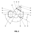
- the housing 14 shown separately and simplified in FIG. 2 the separator 8 has a wall made of metal.
- the housing 14 becomes pressure-tight from an aluminum alloy poured.
- the housing 14 has six with flanges 15 to 20 openings provided.
- the housing 14 has also a longitudinal axis 21, which at the same time the Central axis of the active parts opening into the housing 14 represents the gas-insulated switchgear.
- the one with the Flanges 15 and 16 provided openings are at the Isolator assembly with one partition isolator 22, 23 each sealed gastight, as shown schematically in Fig.3 is.
- the opening provided with the flange 17 becomes when installing the isolator with a metallic cover 24 provided, which has a flange 25 which with the flange 17 is screwed gas-tight. Opposite the flange 25 is a further flange 26 is attached to the cover 24. Of the Flange 26 is used to attach a pressure-resistant bushing for one in a switching operation of the disconnector 8 in Direction of an actuating axis 27 movable insulating rod 28. The insulating rod 28 moves through one Disconnector drive 29 also connected to the flange 26 driven, the movable, highly schematized Contact arrangement 30 of the disconnector 8.
- the movable Contact arrangement 30 is of a dielectric type Shield 30a surrounded by the insulating rod 28th is penetrated.
- the longitudinal axis 21 and the actuation axis 27 lie in one plane and they intersect at an angle ⁇ .
- the angle ⁇ is carried out here at 60 °.
- Through the interface 31 of the longitudinal axis 21 with the Actuating axis 27 leads a further axis 32, which with the Actuating axis 27 forms an angle ⁇ , which here as right angle is formed.
- the axis 32 forms with the Longitudinal axis 21 an angle ⁇ .
- the angle ⁇ is 30 ° here executed.
- angles ⁇ are also possible if the other angles are modified accordingly, an angular range from 25 ° to 35 ° for this angle ⁇ can be useful realize. It affects the arrangement of the Isolator 8 is advantageous when the sum of the angles of the angle a and the angle ⁇ 90 °.
- the openings provided with the flanges 18 and 19 are provided for the optional installation of an earth 9, thereby the earth electrode 9 can either, as shown in Fig.1, above the housing 14 are installed or below, if require the concept of gas-insulated switchgear should.
- On the remaining of the two flanges 18, 19 can, for example, detectors for monitoring the gas-insulated switchgear or, as shown in Fig.3, a Rupture disk 33 are flanged pressure-tight, which in Failure allows pressure relief of the housing 14.
- the two flanges 18, 19 have a common installation axis 34 on.
- the flange 20 is also for the pressure tight Installation of an earth 10 is provided, which is along a Installation axis 35 extends.
- the two mounting axles 34.35 lie here in one plane with the actuation axis 27 what results in a particularly space-saving arrangement. For special ones The axes mentioned can also be used in various applications Levels.
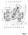
- the section through a separator according to the invention 3 shows the active parts of the isolator 8 in a highly simplified manner. Due to the partition isolators 22, 23, one of each two that can be brought to high voltage potential and opposite the Metal encapsulation of the gas-insulated switchgear potential shielded power connections 36,37 out. Of the Power connector 36 is fixed with a first one Contact carrier 38 of the disconnector 8 electrically connected. The power connector 37 has a second fixed one Contact carrier 39 of the disconnector 8 electrically connected.
- the contact carriers 38, 39 are made of several, here components not shown assembled.
- the contact carriers 38, 39 have a dielectric design, any edges are shielded.
- a tulip-shaped Counter contact 40 embedded which is concentric to the mounting axis 34 is arranged and the contact pin 41 of the Erders 9 picks up when the Erder 9 is closed.
- the fixed contact 42 of the Isolator 8 embedded which is concentric to the actuation axis 27 is arranged.
- the contact carrier 38 is after the power connection 36 initially concentric to the longitudinal axis 21 arranged, the adjoining part of the contact carrier 38 is angled so that it, as in Fig.3 shown, extends somewhat below the longitudinal axis 21.
- a surface 43 of this angled part extends perpendicular to the actuation axis 27.
- a tulip-shaped counter contact 44 is embedded, which is arranged concentrically to the installation axis 35 and which receives the contact pin 45 of the earth 10 when the Earth 10 is closed.
- a sliding contact 46 which is for the current transfer from the movable contact arrangement 30 of the disconnector 8 is provided on the contact carrier 39.
- the sliding contact 46 is arranged concentrically to the actuation axis 27, it is with contact fingers, with contact blades or with spiral contacts Mistake.
- the contact carrier 39 is after the power connection 37 initially arranged concentrically to the longitudinal axis 21, the adjoining part of the contact carrier 39 so that it is slightly bent, as shown in Fig.3 extends above the longitudinal axis 21.
- a surface 47 of this angled part extends perpendicular to Actuator axis 27 of the disconnector 8.
- the two surfaces 43 and 44 run parallel to one another at a distance 48, they are inclined by the angle ⁇ against the longitudinal axis 21.
- the surfaces 43 and 44 decrease with increasing distance the actuation axis 27 in strongly rounded areas.
- This distance 48 corresponds to the isolating distance of the isolator 8, all those occurring in operation at this point withstands operational stresses.
- the disconnector drive 29 is designed that it has the movable contact arrangement in every possible operating case 30 safely into the intended switch-on position moved, so that a perfect power supply over the for it provided nominal current contacts, not described in detail is guaranteed.
- the opening of the Isolator 8 always flawless.
- the disconnector 8 can be installed in any installation position through the system concept of metal encapsulated gas-insulated switchgear is specified.
- the earth electrodes 9.10 can also be operated regardless of position, so that too therefore there are no installation restrictions.
- the earth electrode 9.10 can be used as a work earth as well as a quick earth be trained.
- the assembly isolator 8 with front and downstream earthing 9.10 is very compact and takes up particularly little space in the axial direction, so that the panel with particularly small dimensions can be executed.
Landscapes
- Engineering & Computer Science (AREA)
- Power Engineering (AREA)
- Gas-Insulated Switchgears (AREA)
- Arc-Extinguishing Devices That Are Switches (AREA)
Claims (9)
- Sectionneur pour un appareillage de commutation blindé métallique à haute tension et à isolement gazeux, lequel présente des parties actives sous tension s'étendant le long d'un axe longitudinal (21) d'un boítier rempli de gaz isolant, muni de deux supports de contact (38, 39), une première section de chacun s'étendant le long de l'axe longitudinal (21) et une deuxième section qui vient s'y raccorder étant pliée par rapport à l'axe longitudinal (21), avec un écart (48) conçu comme une section de séparation entre les surfaces (43, 47) parallèles l'une à l'autre des deux supports de contact (38, 39), avec un arrangement de contact mobile (30) le long d'un axe de manoeuvre (27) qui court-circuite électriquement l'écart (48) conçu comme une section de séparation lorsque le sectionneur (8) est enclenché, l'axe longitudinal (21) et l'axe de manoeuvre (27) se croisant en formant un premier angle (α), caractérisé par le faitque les surfaces (43, 47) parallèles l'une à l'autre sont chacune disposées sur une partie de la deuxième section venant se raccorder à la première section, etque ces surfaces (43, 47) sont pliées par rapport à l'axe longitudinal (21) selon un deuxième angle (β).
- Sectionneur selon la revendication 1, caractérisé par le fait que la somme angulaire du premier angle (α) et du deuxième angle (β) donne une valeur de 90°.
- Sectionneur selon la revendication 2, caractérisé par le fait que le deuxième angle (β) peut être compris entre 25° et 35°, de préférence cependant égal à 30°.
- Sectionneur selon l'une des revendications 1 à 3, caractérisé par le fait que l'axe longitudinal (21) et l'axe de manoeuvre (27) se trouvent dans un même plan.
- Sectionneur selon l'une des revendications 1 à 4, caractérisé par le fait que les surfaces (43, 47) des deux supports de contact (38, 39) sont inclinées selon un troisième angle (δ) dans la zone de la section de séparation par rapport à l'axe de manoeuvre (27) du sectionneur (8).
- Sectionneur selon la revendication 5, caractérisé par le fait que l'angle (δ) est un angle droit.
- Sectionneur selon l'une des revendications 1 à 6, caractérisé par le fait qu'au moins une possibilité de montage d'une prise de terre (9, 10) présentant un axe de montage (34, 35) est prévue dans le boítier (14) des deux côtés de la section de séparation.
- Sectionneur selon la revendication 7, caractérisé par le fait que les axes de montage (34, 35) sont perpendiculaires à l'axe longitudinal (21).
- Sectionneur selon la revendication 8, caractérisé par le fait que les axes de montage (34, 35) des prises de terre (9, 10) se trouvent dans un même plan que l'axe de manoeuvre (27).
Applications Claiming Priority (2)
| Application Number | Priority Date | Filing Date | Title |
|---|---|---|---|
| CH121694 | 1994-04-19 | ||
| CH1216/94 | 1994-04-19 |
Publications (2)
| Publication Number | Publication Date |
|---|---|
| EP0678952A1 EP0678952A1 (fr) | 1995-10-25 |
| EP0678952B1 true EP0678952B1 (fr) | 1998-08-26 |
Family
ID=4205214
Family Applications (1)
| Application Number | Title | Priority Date | Filing Date |
|---|---|---|---|
| EP94110054A Expired - Lifetime EP0678952B1 (fr) | 1994-04-19 | 1994-06-29 | Sectionneur pour un appareillage de commutation blindé métallique à haute tension et à isolement gazeux |
Country Status (8)
| Country | Link |
|---|---|
| US (1) | US5625179A (fr) |
| EP (1) | EP0678952B1 (fr) |
| CN (1) | CN1042276C (fr) |
| BR (1) | BR9501706A (fr) |
| CA (1) | CA2142632A1 (fr) |
| DE (1) | DE59406777D1 (fr) |
| RU (1) | RU95105972A (fr) |
| ZA (1) | ZA951569B (fr) |
Cited By (1)
| Publication number | Priority date | Publication date | Assignee | Title |
|---|---|---|---|---|
| EP1128509B2 (fr) † | 2000-02-23 | 2012-09-26 | Areva T&D Sa | Commutateur électrique à trois positions avec un élément de commutation mobile axialement |
Families Citing this family (10)
| Publication number | Priority date | Publication date | Assignee | Title |
|---|---|---|---|---|
| DE19519301A1 (de) * | 1995-05-26 | 1996-11-28 | Abb Management Ag | Trenner für eine metallgekapselte gasisolierte Hochspannungsschaltanlage |
| DE19632574A1 (de) * | 1996-08-13 | 1998-02-19 | Abb Patent Gmbh | Trenn-Erderschalter für eine metallgekapselte, gasisolierte Hochspannungsschaltanlage |
| CN101300720B (zh) * | 2006-03-31 | 2011-08-24 | 三菱电机株式会社 | 气体绝缘电力设备 |
| DE102006053376A1 (de) * | 2006-11-10 | 2008-05-15 | Abb Technology Ag | Elektrische Hochspannugnsanlage |
| DE102009022105A1 (de) | 2009-05-20 | 2010-11-25 | Abb Technology Ag | Gasisolierte Hochspannungsschaltanlage |
| CN102812604B (zh) * | 2010-01-18 | 2015-08-19 | Abb技术有限公司 | 用于电气开关设备的压缩气体绝缘的结构组件的壳体 |
| DE102010004981B3 (de) | 2010-01-18 | 2011-07-21 | Abb Technology Ag | Metallgekapselter, gasisolierter kombinierter Trenn- und Erdungsschalter |
| KR20120127851A (ko) * | 2011-05-16 | 2012-11-26 | 현대중공업 주식회사 | 가스절연 개폐장치 |
| CN105009391A (zh) * | 2013-04-12 | 2015-10-28 | 三菱电机株式会社 | 气体绝缘开关装置 |
| CN108281888A (zh) * | 2017-12-28 | 2018-07-13 | 北京双杰电气股份有限公司 | 一种机构罩 |
Family Cites Families (8)
| Publication number | Priority date | Publication date | Assignee | Title |
|---|---|---|---|---|
| US3806682A (en) * | 1972-10-03 | 1974-04-23 | Bbc Brown Boveri & Cie | High-voltage gas-insulated switchgear with capacitive voltage divider for indicating contact position |
| NL160439C (nl) * | 1975-04-07 | 1979-10-15 | Coq Bv | Vermogensschakelaar voor hoge spanning met bolvormig metalen vat. |
| JPS5379242A (en) * | 1976-12-22 | 1978-07-13 | Fuji Electric Co Ltd | Enclosed-type housing equipment |
| FR2346884A1 (fr) * | 1977-03-29 | 1977-10-28 | Merlin Gerin | Sectionneur de barres de poste blinde haute tension |
| FR2629283B1 (fr) * | 1988-03-22 | 1990-11-30 | Merlin Gerin | Travee d'un poste blinde haute tension |
| JP2625512B2 (ja) * | 1988-08-03 | 1997-07-02 | 株式会社日立製作所 | ガス絶縁開閉装置 |
| DE4210545A1 (de) * | 1992-03-31 | 1993-10-07 | Asea Brown Boveri | Trennschalter für eine metallgekapselte gasisolierte Hochspannungsanlage |
| DE4336951A1 (de) * | 1993-10-29 | 1995-05-04 | Abb Management Ag | Hochspannungsschaltgerät |
-
1994
- 1994-06-29 EP EP94110054A patent/EP0678952B1/fr not_active Expired - Lifetime
- 1994-06-29 DE DE59406777T patent/DE59406777D1/de not_active Expired - Lifetime
-
1995
- 1995-02-16 CA CA002142632A patent/CA2142632A1/fr not_active Abandoned
- 1995-02-24 ZA ZA951569A patent/ZA951569B/xx unknown
- 1995-03-28 US US08/411,563 patent/US5625179A/en not_active Expired - Lifetime
- 1995-04-17 RU RU95105972/07A patent/RU95105972A/ru unknown
- 1995-04-18 BR BR9501706A patent/BR9501706A/pt not_active Application Discontinuation
- 1995-04-18 CN CN95105065A patent/CN1042276C/zh not_active Expired - Lifetime
Cited By (1)
| Publication number | Priority date | Publication date | Assignee | Title |
|---|---|---|---|---|
| EP1128509B2 (fr) † | 2000-02-23 | 2012-09-26 | Areva T&D Sa | Commutateur électrique à trois positions avec un élément de commutation mobile axialement |
Also Published As
| Publication number | Publication date |
|---|---|
| US5625179A (en) | 1997-04-29 |
| DE59406777D1 (de) | 1998-10-01 |
| RU95105972A (ru) | 1997-03-10 |
| CN1115127A (zh) | 1996-01-17 |
| EP0678952A1 (fr) | 1995-10-25 |
| CN1042276C (zh) | 1999-02-24 |
| ZA951569B (en) | 1995-12-12 |
| CA2142632A1 (fr) | 1995-10-20 |
| BR9501706A (pt) | 1995-11-14 |
Similar Documents
| Publication | Publication Date | Title |
|---|---|---|
| EP0744803B1 (fr) | Sectionneur pour une installation de commutation à haute tension, blindé et à isolation gazeuse | |
| EP0688071B2 (fr) | Appareillage de commutation blindé métallique à gaz isolant | |
| DE10351766B4 (de) | Metallgekapselte Schaltvorrichtung | |
| DE3715053C2 (fr) | ||
| EP1719225B1 (fr) | Installation de commutation a isolation gazeuse dans une enveloppe | |
| EP0069693B1 (fr) | Container cylindrique pour une installation haute tension blindée tripolaire à isolation gazeuse | |
| EP0678954B1 (fr) | Appareillage de commutation blindé métallique à isolement gazeux | |
| EP0678955B1 (fr) | Appareillage de commutation blindé métallique à isolement gazeux | |
| EP0678952B1 (fr) | Sectionneur pour un appareillage de commutation blindé métallique à haute tension et à isolement gazeux | |
| DE2924430A1 (de) | Metallgekapselte, sf tief 6 -gasisolierte schaltanlage | |
| EP0651484B1 (fr) | Appareil de coupure à haute tension | |
| DE3436173A1 (de) | Schaltanlage | |
| EP1060548A1 (fr) | Installations de distribution electriques isolees aux gaz, sous enveloppe metallique, munies de recipients remplis de gaz | |
| EP1629581B1 (fr) | Systeme de disjoncteurs | |
| EP0678953B1 (fr) | Terminaison de câble pour un appareillage de commutation blindé métallique à haute tension et à isolement gazeux | |
| EP0875971A2 (fr) | Installation de distribution électrique pour haute tension | |
| DE69505028T2 (de) | Gasisolierte Schaltanlageanordnung | |
| DE69114370T2 (de) | Gasisolierte Schaltvorrichtung. | |
| EP0436256B1 (fr) | Installation de commutation avec un récipient blindé à isolation gazeuse et interrupteur rotatif multiposition | |
| EP0796502B1 (fr) | Appareillage de commutation mis sous boitier metallique, comportant un interrupteur a vide | |
| DE3109669A1 (de) | Kombinationsbaustein (gehaeusebaustein) eines systems zum aufbau vollisolierter schaltanlagen | |
| EP1187157B1 (fr) | Sectionneur | |
| DE19606213A1 (de) | Schaltfeld in einer elektrischen, metallgekapselten, gasisolierten Hochspannungsschaltanlage | |
| DE19540777A1 (de) | Elektrisches Schaltgerät | |
| DE3034021A1 (de) | Elektrische schaltanlage |
Legal Events
| Date | Code | Title | Description |
|---|---|---|---|
| PUAI | Public reference made under article 153(3) epc to a published international application that has entered the european phase |
Free format text: ORIGINAL CODE: 0009012 |
|
| AK | Designated contracting states |
Kind code of ref document: A1 Designated state(s): CH DE FR GB IT LI NL |
|
| RBV | Designated contracting states (corrected) |
Designated state(s): CH DE FR GB IT LI NL |
|
| 17P | Request for examination filed |
Effective date: 19960329 |
|
| RAP1 | Party data changed (applicant data changed or rights of an application transferred) |
Owner name: ASEA BROWN BOVERI AG |
|
| 17Q | First examination report despatched |
Effective date: 19961227 |
|
| GRAG | Despatch of communication of intention to grant |
Free format text: ORIGINAL CODE: EPIDOS AGRA |
|
| GRAG | Despatch of communication of intention to grant |
Free format text: ORIGINAL CODE: EPIDOS AGRA |
|
| GRAH | Despatch of communication of intention to grant a patent |
Free format text: ORIGINAL CODE: EPIDOS IGRA |
|
| GRAH | Despatch of communication of intention to grant a patent |
Free format text: ORIGINAL CODE: EPIDOS IGRA |
|
| GRAA | (expected) grant |
Free format text: ORIGINAL CODE: 0009210 |
|
| AK | Designated contracting states |
Kind code of ref document: B1 Designated state(s): CH DE FR GB IT LI NL |
|
| PG25 | Lapsed in a contracting state [announced via postgrant information from national office to epo] |
Ref country code: NL Free format text: LAPSE BECAUSE OF FAILURE TO SUBMIT A TRANSLATION OF THE DESCRIPTION OR TO PAY THE FEE WITHIN THE PRESCRIBED TIME-LIMIT Effective date: 19980826 Ref country code: GB Free format text: LAPSE BECAUSE OF FAILURE TO SUBMIT A TRANSLATION OF THE DESCRIPTION OR TO PAY THE FEE WITHIN THE PRESCRIBED TIME-LIMIT Effective date: 19980826 |
|
| REG | Reference to a national code |
Ref country code: CH Ref legal event code: EP |
|
| REF | Corresponds to: |
Ref document number: 59406777 Country of ref document: DE Date of ref document: 19981001 |
|
| ET | Fr: translation filed | ||
| NLV1 | Nl: lapsed or annulled due to failure to fulfill the requirements of art. 29p and 29m of the patents act | ||
| GBV | Gb: ep patent (uk) treated as always having been void in accordance with gb section 77(7)/1977 [no translation filed] |
Effective date: 19980826 |
|
| PLBE | No opposition filed within time limit |
Free format text: ORIGINAL CODE: 0009261 |
|
| STAA | Information on the status of an ep patent application or granted ep patent |
Free format text: STATUS: NO OPPOSITION FILED WITHIN TIME LIMIT |
|
| 26N | No opposition filed | ||
| REG | Reference to a national code |
Ref country code: CH Ref legal event code: PFA Free format text: ASEA BROWN BOVERI AG TRANSFER- ABB SCHWEIZ HOLDING AG Ref country code: CH Ref legal event code: NV Representative=s name: ABB SCHWEIZ AG INTELLECTUAL PROPERTY (CH-LC/IP) |
|
| REG | Reference to a national code |
Ref country code: FR Ref legal event code: CD Ref country code: FR Ref legal event code: CA |
|
| REG | Reference to a national code |
Ref country code: CH Ref legal event code: PUE Owner name: ABB SCHWEIZ AG Free format text: ABB SCHWEIZ HOLDING AG#BROWN BOVERI STRASSE 6#5400 BADEN (CH) -TRANSFER TO- ABB SCHWEIZ AG#BROWN BOVERI STRASSE 6#5400 BADEN (CH) |
|
| REG | Reference to a national code |
Ref country code: FR Ref legal event code: TP |
|
| PGFP | Annual fee paid to national office [announced via postgrant information from national office to epo] |
Ref country code: CH Payment date: 20130621 Year of fee payment: 20 Ref country code: DE Payment date: 20130620 Year of fee payment: 20 |
|
| PGFP | Annual fee paid to national office [announced via postgrant information from national office to epo] |
Ref country code: FR Payment date: 20130703 Year of fee payment: 20 Ref country code: IT Payment date: 20130625 Year of fee payment: 20 |
|
| REG | Reference to a national code |
Ref country code: CH Ref legal event code: PL |
|
| REG | Reference to a national code |
Ref country code: DE Ref legal event code: R071 Ref document number: 59406777 Country of ref document: DE |
|
| PG25 | Lapsed in a contracting state [announced via postgrant information from national office to epo] |
Ref country code: DE Free format text: LAPSE BECAUSE OF EXPIRATION OF PROTECTION Effective date: 20140701 |