EP0678603A1 - Mounting device for connecting the end of a coil spring to another element - Google Patents
Mounting device for connecting the end of a coil spring to another element Download PDFInfo
- Publication number
- EP0678603A1 EP0678603A1 EP95420103A EP95420103A EP0678603A1 EP 0678603 A1 EP0678603 A1 EP 0678603A1 EP 95420103 A EP95420103 A EP 95420103A EP 95420103 A EP95420103 A EP 95420103A EP 0678603 A1 EP0678603 A1 EP 0678603A1
- Authority
- EP
- European Patent Office
- Prior art keywords
- spring
- branches
- turns
- elastic
- internal
- Prior art date
- Legal status (The legal status is an assumption and is not a legal conclusion. Google has not performed a legal analysis and makes no representation as to the accuracy of the status listed.)
- Granted
Links
- 239000013013 elastic material Substances 0.000 claims description 2
- 230000000149 penetrating effect Effects 0.000 claims 1
- 238000009941 weaving Methods 0.000 claims 1
- 230000008602 contraction Effects 0.000 description 4
- 230000008030 elimination Effects 0.000 description 2
- 238000003379 elimination reaction Methods 0.000 description 2
- 238000004519 manufacturing process Methods 0.000 description 2
- 239000000463 material Substances 0.000 description 2
- 239000004952 Polyamide Substances 0.000 description 1
- 230000006866 deterioration Effects 0.000 description 1
- 238000002347 injection Methods 0.000 description 1
- 239000007924 injection Substances 0.000 description 1
- 238000009434 installation Methods 0.000 description 1
- 239000002991 molded plastic Substances 0.000 description 1
- 238000000465 moulding Methods 0.000 description 1
- 230000010355 oscillation Effects 0.000 description 1
- 230000035515 penetration Effects 0.000 description 1
- 239000004033 plastic Substances 0.000 description 1
- 229920002647 polyamide Polymers 0.000 description 1
Images


Classifications
-
- D—TEXTILES; PAPER
- D03—WEAVING
- D03C—SHEDDING MECHANISMS; PATTERN CARDS OR CHAINS; PUNCHING OF CARDS; DESIGNING PATTERNS
- D03C3/00—Jacquards
- D03C3/24—Features common to jacquards of different types
- D03C3/40—Constructions of lifting-cords
-
- F—MECHANICAL ENGINEERING; LIGHTING; HEATING; WEAPONS; BLASTING
- F16—ENGINEERING ELEMENTS AND UNITS; GENERAL MEASURES FOR PRODUCING AND MAINTAINING EFFECTIVE FUNCTIONING OF MACHINES OR INSTALLATIONS; THERMAL INSULATION IN GENERAL
- F16F—SPRINGS; SHOCK-ABSORBERS; MEANS FOR DAMPING VIBRATION
- F16F1/00—Springs
- F16F1/02—Springs made of steel or other material having low internal friction; Wound, torsion, leaf, cup, ring or the like springs, the material of the spring not being relevant
- F16F1/04—Wound springs
- F16F1/12—Attachments or mountings
- F16F1/125—Attachments or mountings where the end coils of the spring engage an axial insert
-
- F—MECHANICAL ENGINEERING; LIGHTING; HEATING; WEAPONS; BLASTING
- F16—ENGINEERING ELEMENTS AND UNITS; GENERAL MEASURES FOR PRODUCING AND MAINTAINING EFFECTIVE FUNCTIONING OF MACHINES OR INSTALLATIONS; THERMAL INSULATION IN GENERAL
- F16F—SPRINGS; SHOCK-ABSORBERS; MEANS FOR DAMPING VIBRATION
- F16F13/00—Units comprising springs of the non-fluid type as well as vibration-dampers, shock-absorbers, or fluid springs
- F16F13/02—Units comprising springs of the non-fluid type as well as vibration-dampers, shock-absorbers, or fluid springs damping by frictional contact between the spring and braking means
-
- Y—GENERAL TAGGING OF NEW TECHNOLOGICAL DEVELOPMENTS; GENERAL TAGGING OF CROSS-SECTIONAL TECHNOLOGIES SPANNING OVER SEVERAL SECTIONS OF THE IPC; TECHNICAL SUBJECTS COVERED BY FORMER USPC CROSS-REFERENCE ART COLLECTIONS [XRACs] AND DIGESTS
- Y10—TECHNICAL SUBJECTS COVERED BY FORMER USPC
- Y10T—TECHNICAL SUBJECTS COVERED BY FORMER US CLASSIFICATION
- Y10T24/00—Buckles, buttons, clasps, etc.
- Y10T24/31—Plural fasteners having intermediate flaccid connector
Definitions
- the present invention relates to devices for assembling or connecting the end of a helical spring with respect to another member and it relates more particularly, although not exclusively, to a device for assembling between one of the ends of a helical spring and the base of a loom, the other end of said spring also being associated with the arm of an armor mechanism.
- each hook of a Verdol-type armor mechanism is associated with a multiplicity of cords constituting what is called a harness, each cord being attached to the upper end of a heddle, the lower end of which is associated with the upper end of a helical spring, the other end of which is fixed.
- the known assembly or connection devices between the end of a helical spring and another member such as a fixed member are generally made of a molded plastic material and they comprise a threaded endpiece which engages by screwing in the first turns of the corresponding end of the helical spring. Said devices also comprise means for hooking to another member.
- One of the devices in question which was the subject of patent application 2 674 264, further comprises a cylindrical piece of elastic material engaged by force in the corresponding end of the spring so as to dampen its oscillations.
- Such a device is unusable because the introduction of the cylindrical part inside the turns of the spring is extremely difficult and very often results in the deterioration of the turns because the return springs for heald looms are of very small dimensions.
- Such a spring is for example made with wire of very small diameter wound to form turns of about 2 mm in diameter.
- the cylindrical part which is the subject of patent application 2 674 264 is replaced by an element consisting of at least two elastic branches capable of cooperating with the end of the spring in order to generate with the turns of this end a friction which suppresses the resonance of this when it is subjected to rapid successive pulls.
- Fig. 1 is a very schematic view of part of a mechanical armor harness, the heddles of which are each recalled by a helical spring.
- Fig. 2 is a perspective view illustrating a first embodiment of an assembly or connection device according to the invention.
- Fig. 3 is a sectional view illustrating the device of FIG. 2 in the assembled state with respect to the end of a spring and of another member in order to connect the latter to the spring.
- Fig. 4 is a section on a larger scale along IV-IV (fig. 3).
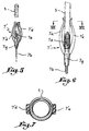
- Fig. 5 illustrates in perspective an alternative embodiment of the device of FIG. 2.
- Fig. 6 is an exterior view showing the device of FIG. 5 in the assembled state with respect to the end of a spring.
- Fig. 7 is a section on a larger scale along VII-VII (fig. 6).
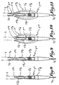
- Fig. 8 illustrates yet another embodiment of the device according to the invention.
- Fig. 9 shows an assembly device according to the invention produced by combining the devices in FIG. 2 and 8.
- Fig. 10 is an illustration of another embodiment of the invention, consisting in combining the devices of FIG. 5 and 8.
- Fig. 11 illustrates a last embodiment of the invention consisting of an assembly device produced by combining the devices illustrated in FIG. 5 and 9.
- FIG. 1 Illustrated very schematically in FIG. 1 a part of an armor mechanism 1 comprising a multiplicity of hooks of which only one 2 has been shown.
- the lower end of this hook is associated with a multiplicity of cords 3 forming, in the well-known manner, a harness, while the other end of each cord is hooked to the upper end of a heddle 4, the lower end is associated at the upper end of a helical spring 5.
- the lower end of the latter is fixed to a fixed member 6 via a connection 7.
- Each smooth course comprises a grommet 4 has crossed by a warp yarn 8.
- the connecting device 7 established according to the invention is produced in the form of a device comprising first of all in the known manner a threaded end piece 7 a which is extended downwards by a rod 7 b ending in a harpoon 7 c suitable for engaging in a perforation 6 a of the fixed member 6.
- the harpoon 7 c has a transverse opening 7 h disposed near its tip to facilitate, by contraction of the walls of this opening, the passage of the redents of said tip.
- a transverse opening 7 h disposed near its tip to facilitate, by contraction of the walls of this opening, the passage of the redents of said tip.
- the threaded end piece 7 a is extended opposite the harpoon 7 c by two elastic branches 7 d , 7 e slightly divergent.
- the outer faces of the branches 7 d , 7 e are roughly inscribed in a circumference whose diameter is greater than that of the internal spring 5. It can be seen that the rod 7 b has a stop 7 g of larger diameter .
- the device according to the invention is produced by molding, advantageously by injection of a single piece, from a plastic material such as a polyamide.
- This manufacturing process is very economical and makes it possible to obtain an assembly device which is resistant to traction (fig. 3).
- fig. 4 that in cross section, the outer faces of the two branches 7 d , 7 e can be curved so as to cooperate as best as possible with the inside of the turns of the spring 5. The radius of curvature of said outer faces being close to that of inside the spring.
- a connecting device 7 ′ is provided, the branches 7 ′ d and 7 ′ e of which come from the stop 7 g and extend on either side of the threaded end piece 7 a . It is observed that the branches 7 ′ d , 7 ′ e are convergent, so that on at least part of the surface of their opposite internal faces, said faces are distant by a value less than the external diameter of spring 5.
- the two branches 7 '' d , 7 '' e are cowbes and joined at their free ends to form a point 7 '' f .
- the outer faces of the branches 7 '' d , 7 '' e are roughly shaped in a circumference whose diameter is greater than that of the internal spring 5.
- connection device is constituted by the combination of the connections illustrated in FIG. 2 and 8.
- This preferred embodiment of the invention therefore comprises, starting from the threaded end 7 ''' with two elastic curved branches 7''' d , 7 ''' e joined at their free ends to form a base 7 ''' f from which the two similar divergent branches 7 d and 7 e of FIG. 2.
- the installation of the connecting device 7 '''inside the spring 5 is carried out by successively introducing the two divergent branches then the two curved branches inside the spring, the penetration taking place until that the end of the spring comes to bear against the stop 7 ''' g .
- This embodiment allows a double contact with the turns spring to allow better elimination of resonance.
- connection 7 '''' shows the embodiment of the connection 7 '' to which the two converging branches 7 ' d , 7' e of the connection 7 'of FIG. 5.
- two friction zones are obtained with the spring to improve the elimination of the entry into resonance.
- connection 7 '' '' ' combining the connection 7' '' of fig. 9 and that 7 'of fig. 5. This connection makes it possible to create three contact zones with the turns of the spring.
- each spring 5 could be assembled in accordance with the invention on the one hand to a heald 4, on the other hand to a fixed member such as 6.
Landscapes
- Engineering & Computer Science (AREA)
- General Engineering & Computer Science (AREA)
- Mechanical Engineering (AREA)
- Textile Engineering (AREA)
- Springs (AREA)
Abstract
Description
La présente invention se réfère aux dispositifs d'assemblage ou de liaison de l'extrémité d'un ressort hélicoïdal par rapport à un autre organe et elle vise plus particulièrement, bien que non exclusivement, un dispositif d'assemblage entre l'un des bouts d'un ressort hélicoïdal et le sommier d'un métier à tisser, l'autre bout dudit ressort étant en outre associé à la lisse d'une mécanique d'armure.The present invention relates to devices for assembling or connecting the end of a helical spring with respect to another member and it relates more particularly, although not exclusively, to a device for assembling between one of the ends of a helical spring and the base of a loom, the other end of said spring also being associated with the arm of an armor mechanism.
On sait que chaque crochet d'une mécanique d'armure du genre Verdol est associé à une multiplicité de cordons constituant ce qu'on appelle un harnais, chaque cordon étant attaché à l'extrémité supérieure d'une lisse dont l'extrémité inférieure est associée au bout supérieur d'un ressort hélicoïdal dont l'autre bout est fixe.We know that each hook of a Verdol-type armor mechanism is associated with a multiplicity of cords constituting what is called a harness, each cord being attached to the upper end of a heddle, the lower end of which is associated with the upper end of a helical spring, the other end of which is fixed.
Chaque crochet des mécaniques d'armure modernes effectue de très nombreux déplacement en va-et-vient à une cadence élevée, de telle sorte que les ressorts sont soumis à des contraintes d'extension brutales qui entraînent quelquefois leur entrée en résonance et leur rupture. L'expérience a montré que cette rupture s'effectue généralement à quelques spires du bout du ressort qui est attaché à un organe fixe.Each hook of modern armor mechanics performs very many back-and-forth movements at a high rate, so that the springs are subjected to sudden extension stresses which sometimes cause them to resonate and break. Experience has shown that this rupture generally takes place a few turns from the end of the spring which is attached to a fixed member.
Les dispositifs d'assemblage ou de liaison connus entre le bout d'un ressort hélicoïdal et un autre organe tel qu'un organe fixe, sont généralement réalisés en une matière plastique moulée et ils comportent un embout fileté qui s'engage par vissage dans les premières spires du bout correspondant du ressort hélicoïdal. Lesdits dispositifs comportent en outre des moyens d'accrochage à un autre organe.The known assembly or connection devices between the end of a helical spring and another member such as a fixed member, are generally made of a molded plastic material and they comprise a threaded endpiece which engages by screwing in the first turns of the corresponding end of the helical spring. Said devices also comprise means for hooking to another member.
Un des dispositifs en question, qui a fait l'objet d'une demande de brevet 2 674 264, comporte en outre une pièce cylindrique en matériau élastique engagée à force dans l'extrémité correspondante du ressort de manière à amortir ses oscillations.One of the devices in question, which was the subject of
Mais un tel dispositif est inutilisable du fait que l'introduction de la pièce cylindrique à l'intérieur des spires du ressort est extrêmement difficile et entraîne très souvent la détérioration des spires du fait que les ressorts de rappel pour lisses de métier à tisser sont de très faibles dimensions. Un tel ressort est par exemple réalisé avec du fil de très petit diamètre enroulé pour constituer des spires d'environ 2 mm de diamètre.But such a device is unusable because the introduction of the cylindrical part inside the turns of the spring is extremely difficult and very often results in the deterioration of the turns because the return springs for heald looms are of very small dimensions. Such a spring is for example made with wire of very small diameter wound to form turns of about 2 mm in diameter.
Les perfectionnements qui font l'objet de la présente invention visent à remédier aux inconvénients des dispositifs déjà connus.The improvements which are the subject of the present invention aim to remedy the drawbacks of the devices already known.
A cet effet, la pièce cylindrique faisant l'objet de la demande de brevet 2 674 264 est remplacée par un élément constitué d'au moins deux branches élastiques propres à coopérer avec l'extrémité du ressort en vue d'engendrer avec les spires de cette extrémité un frottement qui supprime la résonance de celui-ci lorsqu'il est soumis à des tractions successives rapides.To this end, the cylindrical part which is the subject of
Le dessin annexé, donné à titre d'exemple, permettra de mieux comprendre l'invention, les caractéristiques qu'elle présente et les avantages qu'elle est susceptible de procurerThe appended drawing, given by way of example, will allow a better understanding of the invention, the characteristics which it presents and the advantages which it is capable of providing.
Fig. 1 est une vue très schématique d'une partie d'un harnais de mécanique d'armure dont les lisses sont chacune rappelées par un ressort hélicoïdal.Fig. 1 is a very schematic view of part of a mechanical armor harness, the heddles of which are each recalled by a helical spring.
Fig. 2 est une vue en perspective illustrant un premier mode d'excécution d'un dispositif d'assemblage ou de liaison suivant l'invention.Fig. 2 is a perspective view illustrating a first embodiment of an assembly or connection device according to the invention.
Fig. 3 est une vue en coupe illustrant le dispositif de fig. 2 à l'état monté par rapport à l'extrémité d'un ressort et d'un autre organe afin de relier ce dernier au ressort.Fig. 3 is a sectional view illustrating the device of FIG. 2 in the assembled state with respect to the end of a spring and of another member in order to connect the latter to the spring.
Fig. 4 est une coupe à plus grande échelle suivant IV-IV (fig. 3).Fig. 4 is a section on a larger scale along IV-IV (fig. 3).
Fig. 5 illustre en perspective une variante d'exécution du dispositif de fig. 2.Fig. 5 illustrates in perspective an alternative embodiment of the device of FIG. 2.
Fig. 6 est une vue extérieure montrant le dispositif de fig. 5 à l'état monté par rapport à l'extrémité d'un ressort.Fig. 6 is an exterior view showing the device of FIG. 5 in the assembled state with respect to the end of a spring.
Fig. 7 est une coupe à plus grande échelle suivant VII-VII (fig. 6).Fig. 7 is a section on a larger scale along VII-VII (fig. 6).
Fig. 8 illustre encore une autre forme d'exécution du dispositif suivant l'invention.Fig. 8 illustrates yet another embodiment of the device according to the invention.
Fig. 9 montre un dispositif d'assemblage suivant l'invention réalisé par combinaison des dispositifs de fig. 2 et 8.Fig. 9 shows an assembly device according to the invention produced by combining the devices in FIG. 2 and 8.
Fig. 10 est une illustration d'un autre mode d'exécution de l'invention, consistant à combiner les dispositifs de fig. 5 et 8.Fig. 10 is an illustration of another embodiment of the invention, consisting in combining the devices of FIG. 5 and 8.
Fig. 11 illustre un dernier mode de réalisation de l'invention consistant en un dispositif d'assemblage réalisé par combinaison des dispositifs illustrés en fig. 5 et 9.Fig. 11 illustrates a last embodiment of the invention consisting of an assembly device produced by combining the devices illustrated in FIG. 5 and 9.
On a illustré très schématiquement en fig. 1 une partie d'une mécanique d'armure 1 comportant une multiplicité de crochets dont un seul 2 a été représenté.Illustrated very schematically in FIG. 1 a part of an
L'extrémité inférieure de ce crochet est associée à une multiplicité de cordons 3 formant, à la manière bien connue, un harnais, tandis que l'autre extrémité de chaque cordon est accrochée à l'extrémité supérieure d'une lisse 4 dont l'extrémité inférieure est associée au bout supérieur d'un ressort hélicoïdal 5. Le bout inférieur de ce dernier est fixé à un organe fixe 6 au moyen d'une liaison 7. Chaque lisse comporte bien entendu un oeillet 4a traversé par un fil de chaîne 8.The lower end of this hook is associated with a multiplicity of
Comme illustré en fig. 2, le dispositif de liaison 7 établi suivant l'invention est réalisé sous la forme d'un dispositif comportant tout d'abord à la manière connue un embout fileté 7a qui se prolonge vers le bas par une tige 7b se terminant par un harpon 7c propre à s'engager dans une perforation 6a de l'organe fixe 6.As illustrated in fig. 2, the connecting
On observe que le harpon 7c comporte une ouverture transversale 7h disposée près de sa pointe pour faciliter, par contraction des parois de cette ouverture, le passage des redents de ladite pointe. Pour maintenir parfaitement le harpon dans la perforation 6a de l'organe 6, c'est-à-dire pour éviter tout mouvement axial dudit harpon dans la perforation, on lui fait comporter une partie souple 7i préférablement creuse dont l'encombrement extérieur est supérieur au diamètre du trou 6a. Ainsi, cette partie souple 7i prend élastiquement appui contre la paroi du trou 6a pour éviter tout jeu axial.It is observed that the
Conformément à l'invention, l'embout fileté 7a se prolonge à l'opposé du harpon 7c par deux branches élastiques 7d, 7e légèrement divergentes. Les faces extérieures des branches 7d, 7e, préférablement arrondies, se trouvent en gros inscrites dans une circonférence dont le diamètre est supérieur à celui interne du ressort 5. On observe que la tige 7b comporte une butée 7g de plus grand diamètre.According to the invention, the threaded
Pour assembler le ressort 5 et le dispositif suivant l'invention, il suffit d'engager à force les branches 7d, 7e à l'intérieur du bout correspondant du ressort jusqu'à ce que la première spire de ce dernier vienne prendre appui contre le début de l'embout fileté 7a. Celui-ci est alors vissé par rapport aux spires jusqu'à ce qu'il vienne en contact avec la butée 7g. On crée ainsi un frottement entre les spires libres du ressort qui se trouvent adjacentes aux spires engagées avec l'embout 7a et les branches 7d, 7e de sorte qu'au cours des élongations et des contractions des spires du ressort 5, celles-ci soient freinées ou amorties et ne puissent pas entrer en résonance. A cet effet, le dispositif suivant l'invention est réalisé par moulage, avantageusement par injection d'une seule pièce, en une matière plastique telle qu'une polyamide. Ce procédé de fabrication est très économique et permet l'obtention d'un dispositif d'assemblage qui soit résistant à la traction (fig. 3). On observe en fig. 4 qu'en section transversale, les faces extérieures des deux branches 7d, 7e peuvent être bombées de manière à coopérer le mieux possible avec l'intérieur des spires du ressort 5. Le rayon de courbure desdites faces extérieur étant voisin de celui de l'intérieur du ressort.To assemble the
Suivant une première variante de l'invention illustrée en fig. 5, on a prévu un dispositif de liaison 7' dont les branches 7'd et 7'e sont issues de la butée 7g et s'étendent de part et d'autre de l'embout fileté 7a. On observe que les branches 7'd, 7'e sont convergentes, de telle sorte que sur une partie au moins de la surface de leurs faces intérieures en vis-à-vis, lesdites faces soient distantes d'une valeur inférieure au diamètre extérieur du ressort 5.According to a first variant of the invention illustrated in FIG. 5, a connecting
Pour assembler le ressort 5 et le dispositif de liaison 7' suivant la variante considérée, il faut légèrement écarter les deux branches 7'd, 7'e, puis introduire le bout correspondant du ressort 5 entre ces branches pour que l'embout fileté 7a vienne se visser avec les spires dudit bout jusqu'à ce que celui-ci vienne porter contre la butée 7g. En relâchant les deux branches, elles compriment légèrement le ressort et créent avec ses spires libres un frottement évitant l'entrée en résonance du ressort lors de ses élongations et de ses contractions (fig. 6). Comme illustré en fig. 7 les faces internes des branches 7'd, 7'e pourraient être prévues concaves de manière à bien coopérer avec l'extérieur des spires du ressort 5.To assemble the
Suivant le mode d'exécution de fig. 8 qui constitue une variante 7'' du dispositif de liaison, les deux branches 7''d, 7''e sont cowbes et réunies au niveau de leurs extrémités libres pour former une pointe 7''f. Comme pour le mode d'exécution de fig. 2, les faces extérieures des branches 7''d, 7''e se trouvent en gros instrites dans une circonférence dont le diamètre est supérieur à celui interne du ressort 5.According to the embodiment of fig. 8 which constitutes a 7 '' variant of the connecting device, the two branches 7 '' d , 7 '' e are cowbes and joined at their free ends to form a point 7 '' f . As for the embodiment of fig. 2, the outer faces of the branches 7 '' d , 7 '' e are roughly shaped in a circumference whose diameter is greater than that of the
Pour assembler le ressort 5 et le dispositif de liaison 7'', il suffit d'engager à force les branches 7''d, 7''e à l'intérieur du ressort jusqu'à ce que sa première spire vienne coopérer avec le début de l'embout fileté 7''a. Celui-ci est alors vissé par rapport aux spires jusqu'à ce que le bout du ressort vienne en contact de la butée 7''g. Les spires du ressort adjacentes à celles qui coopèrent avec l'embout fileté 7''a sont alors légèrement écartées pour créer un frottement afin que le ressort ne puisse pas entrer en résonance lors de ses élongations et de ses contractions.To assemble the
Une autre variante 7''' du dispositif de liaison suivant l'invention est constituée par la combinaison des liaisons illustrées en fig. 2 et 8. Ce mode d'exécution préféré de l'invention comprend donc en partant de l'embout fileté 7'''a deux branches courbes élastiques 7'''d, 7'''e réunies au niveau de leurs extrémités libres pour former une embase 7'''f à partir de laquelle partent les deux branches divergentes semblables 7d et 7e de fig. 2.Another variant 7 '''of the connection device according to the invention is constituted by the combination of the connections illustrated in FIG. 2 and 8. This preferred embodiment of the invention therefore comprises, starting from the threaded end 7 ''' with two elastic curved branches 7''' d , 7 ''' e joined at their free ends to form a base 7 ''' f from which the two similar
La mise en place du dispositif de liaison 7''' à l'intérieur du ressort 5 s'effectue en introduisant successivement les deux branches divergentes puis les deux branches courbes à l'intérieur du ressort, la pénétration s'effectuant jusqu'à ce que le bout du ressort vienne porter contre la butée 7'''g. Ce mode d'exécution permet un double contact avec les spires de ressort pour permettre une meilleure élimination de la résonance.The installation of the connecting device 7 '''inside the
La liaison 7'''' suivant fig. 10 reprend le mode d'exécution de la liaison 7'' à laquelle on a adjoint les deux branches convergentes 7'd, 7'e de la liaison 7' de fig. 5. Là encore, on obtient deux zones de friction avec le ressort pour améliorer l'élimination de l'entrée en résonance.The connection 7 '''' according to fig. 10 shows the embodiment of the connection 7 '' to which the two converging branches 7 ' d , 7' e of the connection 7 'of FIG. 5. Here again, two friction zones are obtained with the spring to improve the elimination of the entry into resonance.
Enfin, on a illustré en fig. 11 une liaison 7''''' combinant la liaison 7''' de fig. 9 et celle 7' de fig. 5. Cette liaison permet de créer trois zones de contact avec les spires du ressort.Finally, there is illustrated in FIG. 11 a connection 7 '' '' 'combining the connection 7' '' of fig. 9 and that 7 'of fig. 5. This connection makes it possible to create three contact zones with the turns of the spring.
Il va de soi que la partie supérieure ou tête des dispositifs illustrés en fig. 2, 5 et 8 à 11 pourra être fabriquée séparément, c'est-à-dire sans la tige et le harpon pour former une liaison surmoulée au niveau de la butée sur l'extrémité inférieure d'une des lisses 4 illustrées en fig. 1. Grâce à cette structure, les deux bouts de chaque ressort 5 pourraient être assemblés conformément à l'invention d'une part à une lisse 4, d'autre part à un organe fixe tel que 6.It goes without saying that the upper part or head of the devices illustrated in FIG. 2, 5 and 8 to 11 can be manufactured separately, that is to say without the rod and the harpoon to form a molded connection at the level of the stop on the lower end of one of the
Conformément à une autre variante de l'invention, on prévoit la réalisation d'un organe réalisé au moyen de deux dispositifs 7 orientés en opposition l'un par rapport à l'autre par leur butée, de manière qu'ils puissent respectivement coopérer avec les bouts de deux ressorts afin de les assembler dans le prolongement l'un de l'autre et d'éviter leur entrée en résonance.According to another variant of the invention, provision is made for the production of a member produced by means of two
Claims (9)
Applications Claiming Priority (2)
| Application Number | Priority Date | Filing Date | Title |
|---|---|---|---|
| FR9405043 | 1994-04-19 | ||
| FR9405043A FR2718810B1 (en) | 1994-04-19 | 1994-04-19 | Device for assembling the end of a helical spring with respect to another member. |
Publications (2)
| Publication Number | Publication Date |
|---|---|
| EP0678603A1 true EP0678603A1 (en) | 1995-10-25 |
| EP0678603B1 EP0678603B1 (en) | 1997-09-17 |
Family
ID=9462530
Family Applications (1)
| Application Number | Title | Priority Date | Filing Date |
|---|---|---|---|
| EP95420103A Expired - Lifetime EP0678603B1 (en) | 1994-04-19 | 1995-04-18 | Mounting device for connecting the end of a coil spring to another element |
Country Status (6)
| Country | Link |
|---|---|
| US (1) | US5819809A (en) |
| EP (1) | EP0678603B1 (en) |
| JP (1) | JP3538473B2 (en) |
| DE (1) | DE69500715T2 (en) |
| ES (1) | ES2108545T3 (en) |
| FR (1) | FR2718810B1 (en) |
Cited By (6)
| Publication number | Priority date | Publication date | Assignee | Title |
|---|---|---|---|---|
| WO1998024956A1 (en) * | 1996-12-06 | 1998-06-11 | Tardy Jean Jacques | Damping device for jacquard loom heald spring |
| FR2756848A1 (en) * | 1996-12-06 | 1998-06-12 | Tardy Jean Jacques | Jacquard heald damper reducing vibration during loom use |
| EP0893521A1 (en) * | 1997-07-23 | 1999-01-27 | Staubli Lyon | End fitting for a weaving loom element, element with such an end fitting and weaving loom with such an element |
| EP1096049A1 (en) * | 1999-10-28 | 2001-05-02 | Staubli Lyon | Device and assembly for fixing Jacquard-harness springs and loom with such an assembly |
| WO2002092892A1 (en) * | 2001-05-17 | 2002-11-21 | Deutsche Institute für Textil- und Faserforschung | Spring dampened shedding device |
| GB2566092A (en) * | 2017-09-04 | 2019-03-06 | Kristian Fjelldal Alf | An energy-absorbing structure for a tether line, and a tether line incorporating the same |
Families Citing this family (12)
| Publication number | Priority date | Publication date | Assignee | Title |
|---|---|---|---|---|
| FR2826985A1 (en) * | 2001-07-05 | 2003-01-10 | Amstar Sarl | Jacquard loom heddle wire spring damper comprises plastic rod inside spring with at least one curve in contact with spring's inner surface |
| FR2829511A1 (en) * | 2001-09-11 | 2003-03-14 | Amstar Sarl | Jacquard loom heddle return spring damper, comprises tip with friction damping zone above threaded section engaged with spring |
| BE1015048A4 (en) * | 2002-07-19 | 2004-09-07 | Wiele Michel Van De Nv | DEVICE FOR FIXING OF RETREAT IN HARNESS OF FEATHERS a Jacquard. |
| DE102004044783A1 (en) * | 2004-09-16 | 2006-03-30 | Deutsche Institute für Textil- und Faserforschung (DITF) Stuttgart | Shedding device with deformed spring |
| FR2888256B1 (en) * | 2005-07-06 | 2007-09-21 | Staubli Lyon Sa | DEVICE FOR HANGING BETWEEN ELEMENTS OF A CROWN FORMING DEVICE, METHOD FOR MANUFACTURING THE SAME, AND METHOD FOR ATTACHING THE SAME |
| US8277255B2 (en) * | 2010-12-10 | 2012-10-02 | Tyco Electronics Corporation | Interconnect member for an electronic module with embedded components |
| CN102660822A (en) * | 2012-05-19 | 2012-09-12 | 浙江旷达纺织机械有限公司 | Harness-jacquard spring connecting screw for fixing spring |
| CN102677252A (en) * | 2012-05-24 | 2012-09-19 | 浙江旷达纺织机械有限公司 | Harness wire mounting plastic healed rod for cloth weaving |
| CN102677251A (en) * | 2012-05-24 | 2012-09-19 | 浙江旷达纺织机械有限公司 | Harness cord connecting structure of harness cord assembly |
| FR3027314B1 (en) * | 2014-10-16 | 2019-04-26 | Staubli Lyon | SMOOTH FOR WEAVING AND WEAVING EQUIPMENT EQUIPPED WITH SUCH A SMOOTH |
| FR3027315B1 (en) * | 2014-10-16 | 2019-04-26 | Staubli Lyon | SMOOTH FOR WEAVING AND WORK EQUIPPED WITH SUCH A SMOOTH |
| FR3054246B1 (en) * | 2016-07-25 | 2018-08-31 | Staubli Lyon | SMOOTH FOR JACQUARD BUSINESS, ITS MANUFACTURING PROCESS, AND WEAVING COMPRISING SUCH A SMOOTH |
Citations (5)
| Publication number | Priority date | Publication date | Assignee | Title |
|---|---|---|---|---|
| US4385754A (en) * | 1981-03-16 | 1983-05-31 | General Motors Corporation | Spring-biased lost-motion link assembly |
| DE8913482U1 (en) * | 1989-02-22 | 1990-01-25 | van de Sandt GmbH & Co KG, 4290 Bocholt | Connector for a jacquard weaving harness |
| FR2674264A1 (en) * | 1991-03-21 | 1992-09-25 | Amstar | Sprung return element for a weaving loom heald equipped with a Jacquard dobby |
| EP0533636A1 (en) * | 1991-09-16 | 1993-03-24 | MOLLIFICIO CONTE S.r.l. | A composite return spring for heddles of jacquard, verdol and similar type textile looms |
| EP0547303A1 (en) * | 1991-12-17 | 1993-06-23 | The Perkin-Elmer Corporation | Suspension system for isolating vibrations |
Family Cites Families (6)
| Publication number | Priority date | Publication date | Assignee | Title |
|---|---|---|---|---|
| US393595A (en) * | 1888-11-27 | Hat or bonnet holder | ||
| US2267558A (en) * | 1938-09-15 | 1941-12-23 | Ferntol Patents Ltd | Fastener |
| US4245377A (en) * | 1978-07-24 | 1981-01-20 | Soltes Isaac B | Jewelry chain clasp |
| FR2677999B1 (en) * | 1991-06-20 | 1993-10-08 | Amstar | SPRING RETURN ELEMENT FOR SMOOTH WEAVING EQUIPPED WITH JACQUARD MECHANICS. |
| FR2685015B1 (en) * | 1991-12-12 | 1994-04-01 | Staubli Verdol Sa | QUICK ATTACHMENT FOR CONNECTING AT LEAST ONE FUNICULAR ELEMENT TO THE END OF A CORD. |
| US5379496A (en) * | 1993-07-27 | 1995-01-10 | American Cord & Webbing Co., Inc. | Cord release buckle |
-
1994
- 1994-04-19 FR FR9405043A patent/FR2718810B1/en not_active Expired - Fee Related
-
1995
- 1995-04-17 JP JP09108695A patent/JP3538473B2/en not_active Expired - Fee Related
- 1995-04-18 ES ES95420103T patent/ES2108545T3/en not_active Expired - Lifetime
- 1995-04-18 EP EP95420103A patent/EP0678603B1/en not_active Expired - Lifetime
- 1995-04-18 US US08/423,720 patent/US5819809A/en not_active Expired - Fee Related
- 1995-04-18 DE DE69500715T patent/DE69500715T2/en not_active Expired - Lifetime
Patent Citations (5)
| Publication number | Priority date | Publication date | Assignee | Title |
|---|---|---|---|---|
| US4385754A (en) * | 1981-03-16 | 1983-05-31 | General Motors Corporation | Spring-biased lost-motion link assembly |
| DE8913482U1 (en) * | 1989-02-22 | 1990-01-25 | van de Sandt GmbH & Co KG, 4290 Bocholt | Connector for a jacquard weaving harness |
| FR2674264A1 (en) * | 1991-03-21 | 1992-09-25 | Amstar | Sprung return element for a weaving loom heald equipped with a Jacquard dobby |
| EP0533636A1 (en) * | 1991-09-16 | 1993-03-24 | MOLLIFICIO CONTE S.r.l. | A composite return spring for heddles of jacquard, verdol and similar type textile looms |
| EP0547303A1 (en) * | 1991-12-17 | 1993-06-23 | The Perkin-Elmer Corporation | Suspension system for isolating vibrations |
Cited By (14)
| Publication number | Priority date | Publication date | Assignee | Title |
|---|---|---|---|---|
| WO1998024956A1 (en) * | 1996-12-06 | 1998-06-11 | Tardy Jean Jacques | Damping device for jacquard loom heald spring |
| FR2756848A1 (en) * | 1996-12-06 | 1998-06-12 | Tardy Jean Jacques | Jacquard heald damper reducing vibration during loom use |
| FR2756849A1 (en) * | 1996-12-06 | 1998-06-12 | Tardy Jean Jacques | SHOCK ABSORBER FOR JACQUARD WEAVING SMOOTH SPRING |
| EP0893521A1 (en) * | 1997-07-23 | 1999-01-27 | Staubli Lyon | End fitting for a weaving loom element, element with such an end fitting and weaving loom with such an element |
| FR2766501A1 (en) * | 1997-07-23 | 1999-01-29 | Staubli Lyon | END PIECE FOR WEAVING MATERIAL, ELEMENT PROVIDED WITH SUCH AN END PIECE AND WEAVING APPARATUS PROVIDED WITH SUCH AN ELEMENT |
| EP1096049A1 (en) * | 1999-10-28 | 2001-05-02 | Staubli Lyon | Device and assembly for fixing Jacquard-harness springs and loom with such an assembly |
| FR2800395A1 (en) * | 1999-10-28 | 2001-05-04 | Staubli Lyon | JACQUARD HARNESS SPRING SOLIDARIZATION DEVICE AND ASSEMBLY AND WEAVING EQUIPMENT PROVIDED WITH SUCH AN ASSEMBLY |
| US6302154B1 (en) | 1999-10-28 | 2001-10-16 | Staubli Lyon | Spring connection device and assembly in a jacquard harness |
| WO2002092892A1 (en) * | 2001-05-17 | 2002-11-21 | Deutsche Institute für Textil- und Faserforschung | Spring dampened shedding device |
| DE10124022A1 (en) * | 2001-05-17 | 2002-12-12 | Inst Textil & Faserforschung | Shed forming device with spring damping |
| DE10124022C2 (en) * | 2001-05-17 | 2003-04-10 | Inst Textil & Faserforschung | Shed forming device with spring damping |
| GB2566092A (en) * | 2017-09-04 | 2019-03-06 | Kristian Fjelldal Alf | An energy-absorbing structure for a tether line, and a tether line incorporating the same |
| GB2566092B (en) * | 2017-09-04 | 2022-06-15 | Kristian Fjelldal Alf | An energy-absorbing structure for a tether line, and a tether line incorporating the same |
| US11730985B2 (en) | 2017-09-04 | 2023-08-22 | Alf Kristian FJELLDAL | Energy-absorbing structure for a tether line, and a tether line incorporating the same |
Also Published As
| Publication number | Publication date |
|---|---|
| JP3538473B2 (en) | 2004-06-14 |
| US5819809A (en) | 1998-10-13 |
| JPH0835143A (en) | 1996-02-06 |
| EP0678603B1 (en) | 1997-09-17 |
| FR2718810B1 (en) | 1996-06-14 |
| DE69500715T2 (en) | 1998-01-08 |
| DE69500715D1 (en) | 1997-10-23 |
| ES2108545T3 (en) | 1997-12-16 |
| FR2718810A1 (en) | 1995-10-20 |
Similar Documents
| Publication | Publication Date | Title |
|---|---|---|
| EP0678603B1 (en) | Mounting device for connecting the end of a coil spring to another element | |
| US20070017592A1 (en) | Device for hooking between elements of a shed forming device, method for manufacturing it and method for hooking by means of such a device | |
| FR2930305A1 (en) | FIXING DEVICE FOR ASSEMBLING OBJECTS, THEN RELEASING THEM QUICKLY | |
| EP1931235B1 (en) | Grommet | |
| FR2674264A1 (en) | Sprung return element for a weaving loom heald equipped with a Jacquard dobby | |
| FR2544809A1 (en) | TILTING BASE ANCHOR DEVICE | |
| EP0214074A1 (en) | Force transducer for the shedding mechanism of a loom | |
| EP2111098B1 (en) | Device for unwinding a flexible support wire for vines | |
| EP0040384A1 (en) | Apparatus for locking-unlocking a cable on an insulator cap | |
| EP1096049B1 (en) | Device and assembly for fixing Jacquard-harness springs and loom with such an assembly | |
| FR2915754A1 (en) | ROD FOR A DRAWING SYSTEM AND WOVEN WEAVING COMPRISING SUCH A LINK. | |
| EP0915195A1 (en) | Device for connecting a heddle with a harness cord, heddle with such a device and loom with such a heddle | |
| FR2756849A1 (en) | SHOCK ABSORBER FOR JACQUARD WEAVING SMOOTH SPRING | |
| FR2812007A1 (en) | SMOOTH FRAME FOR A WEAVING MACHINE HAVING A HARNESS DAMPING DEVICE AND HAIR DAMPING DEVICE | |
| FR2990008A1 (en) | Self locking assembly collar for assembling and fixing e.g. electric cables, against wall, has stop notches mounted to pivot in flexible manner, and blocking head comprising locking notch mounted in fixed position at inlet | |
| EP0893521A1 (en) | End fitting for a weaving loom element, element with such an end fitting and weaving loom with such an element | |
| FR3120542A1 (en) | Set of guide eyelets and sports racket fitted with such a set | |
| FR2677999A1 (en) | Sprung return element for a heald of a weaving loom equipped with a Jacquard-type dobby | |
| FR2499106A1 (en) | ADJUSTABLE CLIP FOR LOCKING DRAWING CABLES ON SUSPENSION LEVERS OF NEGATIVE TYPE TEXTILE RAILS | |
| FR2743980A1 (en) | Wire retaining clip for grape vine trellis | |
| FR2826985A1 (en) | Jacquard loom heddle wire spring damper comprises plastic rod inside spring with at least one curve in contact with spring's inner surface | |
| FR2829511A1 (en) | Jacquard loom heddle return spring damper, comprises tip with friction damping zone above threaded section engaged with spring | |
| EP2037728A1 (en) | Device for training creeping plants | |
| FR2745242A1 (en) | Hanger for tubular exhaust pipe of vehicle | |
| BE462675A (en) |
Legal Events
| Date | Code | Title | Description |
|---|---|---|---|
| PUAI | Public reference made under article 153(3) epc to a published international application that has entered the european phase |
Free format text: ORIGINAL CODE: 0009012 |
|
| AK | Designated contracting states |
Kind code of ref document: A1 Designated state(s): BE CH DE ES FR GB IT LI |
|
| ITCL | It: translation for ep claims filed |
Representative=s name: MODIANO & ASSOCIATI S.R.L. |
|
| 17P | Request for examination filed |
Effective date: 19951123 |
|
| 17Q | First examination report despatched |
Effective date: 19961022 |
|
| GRAG | Despatch of communication of intention to grant |
Free format text: ORIGINAL CODE: EPIDOS AGRA |
|
| GRAH | Despatch of communication of intention to grant a patent |
Free format text: ORIGINAL CODE: EPIDOS IGRA |
|
| RAP1 | Party data changed (applicant data changed or rights of an application transferred) |
Owner name: STAUBLI LYON |
|
| GRAH | Despatch of communication of intention to grant a patent |
Free format text: ORIGINAL CODE: EPIDOS IGRA |
|
| GRAA | (expected) grant |
Free format text: ORIGINAL CODE: 0009210 |
|
| AK | Designated contracting states |
Kind code of ref document: B1 Designated state(s): BE CH DE ES FR GB IT LI |
|
| REG | Reference to a national code |
Ref country code: CH Ref legal event code: EP |
|
| REF | Corresponds to: |
Ref document number: 69500715 Country of ref document: DE Date of ref document: 19971023 |
|
| GBT | Gb: translation of ep patent filed (gb section 77(6)(a)/1977) |
Effective date: 19971031 |
|
| ITF | It: translation for a ep patent filed | ||
| REG | Reference to a national code |
Ref country code: ES Ref legal event code: FG2A Ref document number: 2108545 Country of ref document: ES Kind code of ref document: T3 |
|
| PLBE | No opposition filed within time limit |
Free format text: ORIGINAL CODE: 0009261 |
|
| STAA | Information on the status of an ep patent application or granted ep patent |
Free format text: STATUS: NO OPPOSITION FILED WITHIN TIME LIMIT |
|
| 26N | No opposition filed | ||
| REG | Reference to a national code |
Ref country code: GB Ref legal event code: IF02 |
|
| PGFP | Annual fee paid to national office [announced via postgrant information from national office to epo] |
Ref country code: GB Payment date: 20050329 Year of fee payment: 11 |
|
| PG25 | Lapsed in a contracting state [announced via postgrant information from national office to epo] |
Ref country code: GB Free format text: LAPSE BECAUSE OF NON-PAYMENT OF DUE FEES Effective date: 20060418 |
|
| GBPC | Gb: european patent ceased through non-payment of renewal fee |
Effective date: 20060418 |
|
| PGFP | Annual fee paid to national office [announced via postgrant information from national office to epo] |
Ref country code: DE Payment date: 20110407 Year of fee payment: 17 |
|
| PGFP | Annual fee paid to national office [announced via postgrant information from national office to epo] |
Ref country code: FR Payment date: 20120426 Year of fee payment: 18 |
|
| PGFP | Annual fee paid to national office [announced via postgrant information from national office to epo] |
Ref country code: ES Payment date: 20120425 Year of fee payment: 18 |
|
| REG | Reference to a national code |
Ref country code: DE Ref legal event code: R119 Ref document number: 69500715 Country of ref document: DE Effective date: 20121101 |
|
| PGFP | Annual fee paid to national office [announced via postgrant information from national office to epo] |
Ref country code: CH Payment date: 20130415 Year of fee payment: 19 Ref country code: BE Payment date: 20130430 Year of fee payment: 19 |
|
| PGFP | Annual fee paid to national office [announced via postgrant information from national office to epo] |
Ref country code: IT Payment date: 20130422 Year of fee payment: 19 |
|
| REG | Reference to a national code |
Ref country code: FR Ref legal event code: ST Effective date: 20131231 |
|
| PG25 | Lapsed in a contracting state [announced via postgrant information from national office to epo] |
Ref country code: FR Free format text: LAPSE BECAUSE OF NON-PAYMENT OF DUE FEES Effective date: 20130430 |
|
| PG25 | Lapsed in a contracting state [announced via postgrant information from national office to epo] |
Ref country code: DE Free format text: LAPSE BECAUSE OF NON-PAYMENT OF DUE FEES Effective date: 20121101 |
|
| REG | Reference to a national code |
Ref country code: CH Ref legal event code: PL |
|
| PG25 | Lapsed in a contracting state [announced via postgrant information from national office to epo] |
Ref country code: LI Free format text: LAPSE BECAUSE OF NON-PAYMENT OF DUE FEES Effective date: 20140430 Ref country code: CH Free format text: LAPSE BECAUSE OF NON-PAYMENT OF DUE FEES Effective date: 20140430 |
|
| PG25 | Lapsed in a contracting state [announced via postgrant information from national office to epo] |
Ref country code: IT Free format text: LAPSE BECAUSE OF NON-PAYMENT OF DUE FEES Effective date: 20140418 |
|
| REG | Reference to a national code |
Ref country code: ES Ref legal event code: FD2A Effective date: 20150527 |
|
| PG25 | Lapsed in a contracting state [announced via postgrant information from national office to epo] |
Ref country code: ES Free format text: LAPSE BECAUSE OF NON-PAYMENT OF DUE FEES Effective date: 20140419 |
|
| PG25 | Lapsed in a contracting state [announced via postgrant information from national office to epo] |
Ref country code: BE Free format text: LAPSE BECAUSE OF NON-PAYMENT OF DUE FEES Effective date: 20140430 |