EP0678432B1 - Detachable grip for a vehicle towed by cable - Google Patents
Detachable grip for a vehicle towed by cable Download PDFInfo
- Publication number
- EP0678432B1 EP0678432B1 EP95410034A EP95410034A EP0678432B1 EP 0678432 B1 EP0678432 B1 EP 0678432B1 EP 95410034 A EP95410034 A EP 95410034A EP 95410034 A EP95410034 A EP 95410034A EP 0678432 B1 EP0678432 B1 EP 0678432B1
- Authority
- EP
- European Patent Office
- Prior art keywords
- cable
- lever
- clamp according
- jaws
- clamp
- Prior art date
- Legal status (The legal status is an assumption and is not a legal conclusion. Google has not performed a legal analysis and makes no representation as to the accuracy of the status listed.)
- Expired - Lifetime
Links
- 230000033001 locomotion Effects 0.000 claims description 9
- 230000005540 biological transmission Effects 0.000 claims description 5
- 230000008878 coupling Effects 0.000 claims description 4
- 238000010168 coupling process Methods 0.000 claims description 4
- 238000005859 coupling reaction Methods 0.000 claims description 4
- 230000006835 compression Effects 0.000 claims description 3
- 238000007906 compression Methods 0.000 claims description 3
- 230000003247 decreasing effect Effects 0.000 claims description 2
- 210000003127 knee Anatomy 0.000 description 10
- 230000007935 neutral effect Effects 0.000 description 6
- 230000002427 irreversible effect Effects 0.000 description 1
- 238000005096 rolling process Methods 0.000 description 1
Images


Classifications
-
- B—PERFORMING OPERATIONS; TRANSPORTING
- B61—RAILWAYS
- B61B—RAILWAY SYSTEMS; EQUIPMENT THEREFOR NOT OTHERWISE PROVIDED FOR
- B61B12/00—Component parts, details or accessories not provided for in groups B61B7/00 - B61B11/00
- B61B12/12—Cable grippers; Haulage clips
- B61B12/125—Cable grippers; Haulage clips for non aerial ropeways, e.g. on or under the ground
Definitions
- the invention relates to a disengageable coupling pliers of a vehicle to a towing cable of a track transport on own site, including a control of the clamp fixed to the bottom of the vehicle, a keel integral with the control mechanism and having a branch vertical, which extends vertically downward towards of the towing cable, being laterally offset from the vertical plane containing the cable and a horizontal branch which extends the vertical branch at right angles and extends across the track above the cable, a pair of jaw carried by the horizontal branch and of which at least one jaw mobile is slidably mounted to come selectively in one closed cable clamping position and in an open position of cable release and transmission device movement between the control mechanism and the movable jaw to control the opening and closing of the clamp, see for example WO 81/02275.
- Cable traction of vehicles in a own site transport has many advantages, particularly simplicity and reliability, but it requires the use of disengageable pliers, for coupling and uncoupling of the vehicle from the cable, the opening and closure are perfectly ensured, in order to avoid any risk of slip of the clamp on the cable and all false maneuver.
- Known clamps are complicated and often combined with multiple control systems to avoid any accident.
- the present invention aims to allow the realization a clamp of simple structure, the operation of which is perfectly reliable and this clamp is characterized in that said motion transmission device comprises a rod rigid, rotatably mounted inside the keel and bearing at its upper end a crank and that the crank is attacked by a spring-loaded toggle of the said mechanism control, likely to occupy an extension position and passing neutral, where the knee brace exerts a force maximum cable tightening and a broken trigger position spring and jaw opening.
- the rigid rod rotatably mounted inside the keel, ensures a reliable connection between the jaws projecting from the bottom of the vehicle and the control mechanism, which is arranged to the shelter directly under the bottom or is incorporated into the latter.
- the position of the jaws is faithfully represented by the position the crank wedged on the upper end of the rod and this crank is attacked by a spring-loaded toggle, which ensures stable opening and closing positions of the pliers.
- the knee switch is controlled by a cylinder, for example hydraulic and the assembly is arranged so that during a jaw closing command, the cylinder exerts during the jaw approach phase almost zero force, this force becoming maximum when tightening the cable and decreasing thereafter to become null or even negative, during the passing the neutral point of the knee lifter.
- the opening of the jaws is ensured as soon as the cylinder has brought the knee switch below the neutral.
- the knee brace comprises one or preferably two levers telescopic, each associated with a compression spring, advantageously constituted by a stack of washers elastic, which stress the telescopic lever in extension.
- One end of the toggle joint is articulated at a fixed point while the opposite end is hinged at the crank.
- the cylinder rod is articulated on the axis of the knee pad.
- the fixed jaw is shaped on the horizontal branch of the keel, which is arranged in a guideway of a slide forming the movable jaw.
- the slide carries a articulation pin of a keyed crank on the lower end of the rigid rod.
- a track 10 on its own site, consists of two running tracks 14.15, each associated with a running track guide 16.17.
- the vehicles 18 traveling on track 10 are provided with running wheels 19 and guide wheels 20, which cooperate with the rolling tracks 14,15 and the guide tracks 16.17.
- These 19,20 wheels are bandaged pneumatic, but it is clear that the invention is applicable to railway tracks and vehicles of any other type.
- a cable tractor 11, in the form of an endless loop with return strand 12, extends in the axis of the track, being guided by pulleys support and holding 13 and being driven by a motor (not shown).
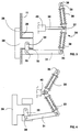
- a clamp is attached to the bottom of the vehicle 18 21, capable of enclosing the cable 11 to couple the vehicle to this tow cable.
- Clamp 21 includes a keel 22, having a vertical branch 23 projecting downwards and laterally offset for crossing the pulleys 13 and a horizontal branch 24, which extends the branch at right angles vertical 23 and extends transversely above the cable 11.
- the horizontal branch 24 carries a pair of jaws 25.26, of which one 25 is fixed and the other 26 is movable to constitute disengageable pliers.
- the movable jaw 26 is connected by a movement transmission device to a mechanism control 27 fixed to the bottom of the vehicle 18. This mechanism 27 controls the opening and closing of the clamp 21 and so coupling and uncoupling of the vehicle 18 to the cable tractor 11.
- the horizontal branch 24 is shaped at its end in a fixed jaw 25, subdivided into two parts, which surround a slide 28, movable transversely to track 10.
- the slide 28 carries, opposite the fixed jaw 25, the movable jaw 26 to form a cable clamping jaw 11.
- a rigid rod vertical 29 In the vertical branch 23 is rotatably mounted a rigid rod vertical 29, at the ends of which are keyed respectively a lower crank 30 and a crank upper 31.
- the lower crank 30 is articulated on a pin 32 carried by slide 28, so as to transform a rotation of the rod 29 in a sliding of the slide 28.
- the upper crank 31 belongs to the control mechanism 27 and it is articulated to a lever 33 of a toggle joint 34, the other lever 35 of which is articulated at a fixed point 36.
- the two levers 33,35 are connected by the axis 37 of the toggle joint 34.
- Each lever 33, 35 is in two telescopic parts, between which a compression spring 38 is interposed, consisting, for example, of a stack of washers elastic, which urge the lever 33,35 in extension.
- AT the axis 37 of the toggle joint 34 is articulated at the end of a rod 39 of a jack 40, for example hydraulic or pneumatic, to control the extension or vice versa the breaking of the knee pad 34.
- the assembly is arranged so that in the position extension of the toggle joint 34, represented in FIG. 3, the jaws 25.26 grip the cable 11 with a clamping force corresponding to that of the springs 38, multiplied by the arms lever lever of the cranks 30.31.
- Neutral knee brace 34 is slightly exceeded and this extension position is thus a stable position for closing the clamp 21.
- the opening of the clamp 21 is controlled by the jack 40, which moves axis 37 of knee lifter 34 to the left on the Figure 3, thereby causing the toggle break 34 and the pivoting of the cranks 30.31 in the opposite direction Clockwise.
- the slide 28 is moved towards the left in the jaws open position 25,26, shown in the figure 4.
- FIG. 5 represents the force exerted by the jack 40 to operate the clamp from the open position O, shown in Figure 4, in position F of Figure 3.
- the toggle system 34 ensures thereafter, due to the gradual arrival in knee extension, a decrease in this force, which becomes zero in neutral and even negative after crossing of the latter. It is clear that as soon as the cylinder has crossed the maximum value of the force the movement of closure continues automatically and the risk of unfinished closure is almost zero.
- the structure of the clamp is simple, in particular the part in projection formed by the jaws 25.26.
Landscapes
- Engineering & Computer Science (AREA)
- Transportation (AREA)
- Mechanical Engineering (AREA)
- Flexible Shafts (AREA)
- Automobile Manufacture Line, Endless Track Vehicle, Trailer (AREA)
- Handcart (AREA)
- Vehicle Body Suspensions (AREA)
- Agricultural Machines (AREA)
- Gripping Jigs, Holding Jigs, And Positioning Jigs (AREA)
- Tents Or Canopies (AREA)
- Vehicle Cleaning, Maintenance, Repair, Refitting, And Outriggers (AREA)
- Installation Of Indoor Wiring (AREA)
- Clamps And Clips (AREA)
Abstract
Description
L'invention est relative à une pince débrayable d'accouplement d'un véhicule à un câble tracteur d'une installation de transport à voie en site propre, comprenant un mécanisme de commande de la pince fixé au fond du véhicule, une quille solidaire du mécanisme de commande et ayant une branche verticale, qui s'étend verticalement vers le bas en direction du câble tracteur, en étant décalée latéralement par rapport au plan vertical contenant le câble et une branche horizontale qui prolonge en équerre la branche verticale et s'étend transversalement à la voie au-dessus du câble, une paire de mors portée par la branche horizontale et dont au moins un mors mobile est monté à coulissement pour venir sélectivement en une position fermé de serrage du câble et en une position ouvert de libération du câble et un dispositif de transmission de mouvement entre le mécanisme de commande et le mors mobile pour commander l'ouverture et la fermeture de la pince, voir par exemple WO 81/02275.The invention relates to a disengageable coupling pliers of a vehicle to a towing cable of a track transport on own site, including a control of the clamp fixed to the bottom of the vehicle, a keel integral with the control mechanism and having a branch vertical, which extends vertically downward towards of the towing cable, being laterally offset from the vertical plane containing the cable and a horizontal branch which extends the vertical branch at right angles and extends across the track above the cable, a pair of jaw carried by the horizontal branch and of which at least one jaw mobile is slidably mounted to come selectively in one closed cable clamping position and in an open position of cable release and transmission device movement between the control mechanism and the movable jaw to control the opening and closing of the clamp, see for example WO 81/02275.
La traction par câble de véhicules d'une installation de transport en site propre présente de nombreux avantages, notamment de simplicité et de fiabilité, mais elle nécessite l'emploi de pinces débrayables, pour l'accouplement et le désaccouplement du véhicule au câble, dont l'ouverture et la fermeture sont parfaitement assurées, afin d'éviter tout risque de glissement de la pince sur le câble et toute fausse manoeuvre. Les pinces connues sont compliquées et souvent associées à de multiples systèmes de contrôle en vue d'éviter tout accident.Cable traction of vehicles in a own site transport has many advantages, particularly simplicity and reliability, but it requires the use of disengageable pliers, for coupling and uncoupling of the vehicle from the cable, the opening and closure are perfectly ensured, in order to avoid any risk of slip of the clamp on the cable and all false maneuver. Known clamps are complicated and often combined with multiple control systems to avoid any accident.
La présente invention a pour but de permettre la réalisation d'une pince de structure simple, dont le fonctionnement est parfaitement fiable et cette pince est caractérisée en ce que ledit dispositif de transmission de mouvement comporte une tige rigide, montée à rotation à l'intérieur de la quille et portant à son extrémité supérieure une manivelle et que la manivelle est attaquée par une genouillère à ressort dudit mécanisme de commande, susceptible d'occuper une position d'extension et de dépassement du point mort, où la genouillère exerce une force maximale de serrage du câble et une position brisée de détente du ressort et d'ouverture des mors.The present invention aims to allow the realization a clamp of simple structure, the operation of which is perfectly reliable and this clamp is characterized in that said motion transmission device comprises a rod rigid, rotatably mounted inside the keel and bearing at its upper end a crank and that the crank is attacked by a spring-loaded toggle of the said mechanism control, likely to occupy an extension position and passing neutral, where the knee brace exerts a force maximum cable tightening and a broken trigger position spring and jaw opening.
La tige rigide, montée à rotation à l'intérieur de la quille, assure une liaison fiable entre les mors en saillie du fond du véhicule et le mécanisme de commande, lequel est disposé à l'abri directement sous le fond ou est incorporé à ce dernier. La position des mors est fidèlement représentée par la position de la manivelle calée sur l'extrémité supérieure de la tige et cette manivelle est attaquée par une genouillère à ressort, qui assure des positions stables d'ouverture et de fermeture de la pince. La genouillère est commandée par un vérin, par exemple hydraulique et l'ensemble est agencé de façon que lors d'une commande de fermeture des mors, le vérin exerce pendant la phase d'approche des mors une force quasi nulle, celle-ci devenant maximale au moment du serrage du câble et décroíssant par la suite pour devenir nulle ou même négative, lors du dépassement du point mort de la genouillère. On comprend qu'à partir du moment où le vérin a franchi la force maximale, le mouvement est irréversible et la fermeture correcte des mors est assurée. D'une manière analogue l'ouverture des mors est assurée dès que le vérin a amené la genouillère en deçà du point mort.The rigid rod, rotatably mounted inside the keel, ensures a reliable connection between the jaws projecting from the bottom of the vehicle and the control mechanism, which is arranged to the shelter directly under the bottom or is incorporated into the latter. The position of the jaws is faithfully represented by the position the crank wedged on the upper end of the rod and this crank is attacked by a spring-loaded toggle, which ensures stable opening and closing positions of the pliers. The knee switch is controlled by a cylinder, for example hydraulic and the assembly is arranged so that during a jaw closing command, the cylinder exerts during the jaw approach phase almost zero force, this force becoming maximum when tightening the cable and decreasing thereafter to become null or even negative, during the passing the neutral point of the knee lifter. We understand that from the moment the cylinder has exceeded the maximum force, the movement is irreversible and correct closing of the jaws is assured. In an analogous manner the opening of the jaws is ensured as soon as the cylinder has brought the knee switch below the neutral.
La genouillère comprend un ou de préférence deux leviers télescopiques, chacun associé à un ressort de compression, avantageusement constitué par un empilage de rondelles élastiques, qui sollicitent le levier télescopique en extension. L'une des extrémité de la genouillère est articulée à un point fixe tandis que l'extrémité opposée est articulée à la manivelle. La tige du vérin est articulé sur l'axe de la genouillère. The knee brace comprises one or preferably two levers telescopic, each associated with a compression spring, advantageously constituted by a stack of washers elastic, which stress the telescopic lever in extension. One end of the toggle joint is articulated at a fixed point while the opposite end is hinged at the crank. The cylinder rod is articulated on the axis of the knee pad.
Le mors fixe est conformé sur la branche horizontale de la quille, laquelle est agencée en glissière de guidage d'un coulisseau formant le mors mobile. Le coulisseau porte un tourillon d'articulation d'une manivelle clavetée sur l'extrémité inférieure de la tige rigide.The fixed jaw is shaped on the horizontal branch of the keel, which is arranged in a guideway of a slide forming the movable jaw. The slide carries a articulation pin of a keyed crank on the lower end of the rigid rod.
D'autres avantages et caractéristiques ressortiront plus
clairement de la description qui va suivre d'un mode de mise en
oeuvre de l'invention donné à titre d'exemple et représenté aux
dessins annexés, dans lesquels:
Sur les figures une voie 10, en site propre, est constituée de
deux pistes de roulement 14,15, chacune associée à une piste de
guidage 16,17. Les véhicules 18 circulant sur la voie 10 sont
pourvus de roues de roulement 19 et de roues de guidage 20, qui
coopèrent respectivement avec les pistes de roulement 14,15 et
les pistes de guidage 16,17. Ces roues 19,20 sont à bandage
pneumatique, mais il est clair que l'invention est applicable à
une voie ferrée et à des véhicules de tout autre type. Un câble
tracteur 11, en forme de boucle sans fin à brin de retour 12,
s'étend dans l'axe de la voie, en étant guidé par des poulies
de support et de maintien 13 et en étant entraíné par un moteur
( non représenté ). Au fond du véhicule 18 est fixée une pince
21, susceptible d'enserrer le câble 11 pour accoupler le
véhicule à ce câble tracteur. La pince 21 comprend une quille
22, ayant une branche verticale 23 en saillie vers le bas et
décalée latéralement pour le franchissement des poulies 13 et
une branche horizontale 24, qui prolonge en équerre la branche
verticale 23 et s'étend transversalement au-dessus du câble 11.
La branche horizontale 24 porte une paire de mors 25,26, dont
l'un 25 est fixe et dont l'autre 26 est mobile pour constituer
une pince débrayable. Le mors mobile 26 est relié par un
dispositif de transmission de mouvement à un mécanisme de
commande 27 fixé au fond du véhicule 18. Ce mécanisme 27
commande l'ouverture et la fermeture de la pince 21 et ainsi
l'accouplement et le désaccouplement du véhicule 18 au câble
tracteur 11.In the figures a
En se référant plus particulièrement aux figures 2-4 on voit
que la branche horizontale 24 est conformée à son extrémité en
un mors fixe 25, subdivisé en deux parties, qui encadrent un
coulisseau 28, mobile transversalement à la voie 10. Le
coulisseau 28 porte, en regard du mors fixe 25, le mors mobile
26 pour constituer une mâchoire de serrage du câble 11. Dans la
branche verticale 23 est montée à rotation une tige rigide
verticale 29, aux extrémités de laquelle sont clavetées
respectivement une manivelle inférieure 30 et une manivelle
supérieure 31. La manivelle inférieure 30 est articulée sur un
tourillon 32 porté par le coulisseau 28, de façon à transformer
une rotation de la tige 29 en un coulissement du coulisseau 28.
La manivelle supérieure 31 appartient au mécanisme de commande
27 et elle est articulée à un levier 33 d'une genouillère 34,
dont l'autre levier 35 est articulé à un point fixe 36. Les
deux leviers 33,35 sont reliés par l'axe 37 de la genouillère
34. Chaque levier 33,35 est en deux parties télescopiques,
entre lesquelles est intercalé un ressort de compression 38,
constitué, par exemple, par un empilage de rondelles
élastiques, qui sollicitent le levier 33,35 en extension. A
l'axe 37 de la genouillère 34 est articulée l'extrémité d'une
tige 39 d'un vérin 40, par exemple hydraulique ou pneumatique,
pour commander l'extension ou inversement la brisure de la
genouillère 34.With particular reference to Figures 2-4 we see
that the
L'ensemble est agencé de manière que dans la position
d'extension de la genouillère 34, représentée à la figure 3,
les mors 25,26 enserrent le câble 11 avec une force de serrage
correspondant à celle des ressorts 38, multipliée par les bras
de levier des manivelles 30,31. Le point mort de la genouillère
34 est légèrement dépassé et cette position d'extension est
ainsi une position stable de fermeture de la pince 21.
L'ouverture de la pince 21 est commandée par le vérin 40, qui
déplace l'axe 37 de la genouillère 34 vers la gauche sur la
figure 3, en provoquant ainsi la brisure de la genouillère 34
et le pivotement des manivelles 30,31 dans le sens inverse des
aiguilles d'une montre. Le coulisseau 28 est déplacé vers la
gauche en position d'ouverture des mors 25,26, représentée à la
figure 4. Dès le franchissement du point mort les ressorts 38
participent à la brisure de la genouillère 34 et la position
d'ouverture est également stable. Une alimentation inverse du
vérin 40 commande bien entendu la fermeture de la pince 21. La
figure 5 représente la force exercée par le vérin 40 pour
actionner la pince de la position ouvert O, représentée à la
figure 4, à la position F de la figure 3. Pendant une première
phase d'approche des mors 25,26 du câble 11 la force est quasi
nulle. Lorsque les mors 25,26 viennent en appui A du câble
cette force augmente rapidement pour atteindre une valeur
maximale. Le système de genouillère 34, selon l'invention,
assure par la suite, du fait de la venue progressive en
extension de la genouillère, une diminution de cette force, qui
devient nulle au point mort et même négative après le
franchissement de ce dernier. Il est clair que dès que le vérin
a franchi la valeur maximale de la force le mouvement de
fermeture se poursuit automatiquement et le risque d'une
fermeture inachevée est quasi nul.The assembly is arranged so that in the position
extension of the
La structure de la pince est simple, notamment la partie en saillie constituée par les mors 25,26.The structure of the clamp is simple, in particular the part in projection formed by the jaws 25.26.
L'invention est bien entendu nullement limitée au mode de mise en oeuvre plus particulièrement décrit en référence aux dessins et elle s'étend à toute variante restant dans le cadre des équivalences.The invention is of course in no way limited to the mode of placing more particularly described with reference to the drawings and it extends to any variant remaining within the framework of equivalences.
Claims (10)
- A disengageable clamp for coupling a vehicle (18) to a traction cable (11) of a reserved lane conveyor (10), comprising a clamp control mechanism (27) secured to the bottom of the vehicle, a pin (22) integral with the control mechanism (27) and having a vertical arm (23) extending vertically downwards towards the traction cable (11) and laterally shifted with respect to the vertical plane containing the cable and a horizontal arm (24) which prolongs the vertical arm (23) at right angles and extends transversely with respect to the lane (10), a pair of jaws (25, 26) carried by the horizontal arm (24) and including at least one mobile jaw (26) mounted sliding so as to selectively attain a closed position in which the cable (11) is clamped and an open position in which the cable is released and a motion transmission device (29-31) between the control mechanism (27) and the mobile jaw (26) to actuate the opening and closing of the clamp, characterised in that said motion transmission device includes a rigid rod (29) mounted rotatable on the pin (22) and carrying a crank (31) at its upper end, and in that the crank (31) is driven by a spring-loaded (38) toggle type lever (34) of said control mechanism (27) capable of occupying an extended position overshooting the dead point in which the lever (34) exerts a maximum cable (11) clamping force, and a folded position in which the spring (38) is released and the jaws (25, 26) are opened.
- A clamp according to claim 1, characterised in that at least one of the levers (33, 35) of the toggle type lever (34) is telescopic and comprises a compression spring (38) exerting a tensile stress on the lever.
- A clamp according to claims 1 or 2, characterised in that one of the ends of the toggle type lever (34) is hinged on said crank (31) and in that the opposite end is hinged on a fixed point (36).
- A clamp according to claims 1, 2 or 3, characterised in that it includes a control actuator (40) which cooperates with the toggle type lever (34) to selectively bring about the extension and folding of the toggle type lever.
- A clamp according to claim 4, characterised in that the actuator (40) acts on the fulcrum member (37) of the two levers (33, 35) of the toggle type lever (34).
- A clamp according to claims 4 or 5, characterised in that the force exerted by the actuator (40) on the toggle type lever (34) to bring the jaws (25, 26) from the open position to the closed position is virtually nil while the jaws are moving towards the cable (11), reaching a maximum value when the jaws rest against the cable and decreasing thereafter to become nil or even inverse when the dead point is overshot.
- A clamp according to any preceding claim, characterised in that the two levers (33, 35) of the toggle type lever (34) are telescopic and in that each lever includes a stack of elastic washers (38) which exert a tensile stress on the lever.
- A clamp according to any preceding claim, characterised in that the lower end of the rotating rod (29) carries a lower crank (30) hinged on the mobile jaw (26) to transform the rotational motion of the rod (29) into a sliding motion of the jaw.
- A clamp according to any preceding claim, characterised in that said horizontal arm (24) is formed as a fixed jaw (25) and designed as a slideway and in that the mobile jaw (26) is formed as a sliding block (28) guided by said slideway.
- A clamp according to claim 9, characterised in that it includes a lower crank (30) with one of its ends fastened to the rigid rod (29) and with its opposite end hinged on a journal (32) carried by the sliding block (28).
Applications Claiming Priority (2)
| Application Number | Priority Date | Filing Date | Title |
|---|---|---|---|
| FR9405120 | 1994-04-22 | ||
| FR9405120A FR2719012B1 (en) | 1994-04-22 | 1994-04-22 | Detachable clamp of a vehicle towed by cable. |
Publications (2)
| Publication Number | Publication Date |
|---|---|
| EP0678432A1 EP0678432A1 (en) | 1995-10-25 |
| EP0678432B1 true EP0678432B1 (en) | 1998-03-04 |
Family
ID=9462591
Family Applications (1)
| Application Number | Title | Priority Date | Filing Date |
|---|---|---|---|
| EP95410034A Expired - Lifetime EP0678432B1 (en) | 1994-04-22 | 1995-04-13 | Detachable grip for a vehicle towed by cable |
Country Status (7)
| Country | Link |
|---|---|
| US (1) | US5520116A (en) |
| EP (1) | EP0678432B1 (en) |
| JP (1) | JP3665106B2 (en) |
| AT (1) | ATE163603T1 (en) |
| CA (1) | CA2146105C (en) |
| ES (1) | ES2116054T3 (en) |
| FR (1) | FR2719012B1 (en) |
Families Citing this family (6)
| Publication number | Priority date | Publication date | Assignee | Title |
|---|---|---|---|---|
| FR2758116B1 (en) | 1997-01-06 | 1999-02-05 | Pomagalski Sa | DETACHABLE CLAMP OF A TRANSPORTATION SYSTEM WITH A TRACTOR CABLE |
| DK1163019T3 (en) | 1999-03-25 | 2008-03-03 | Metabolix Inc | Medical devices and applications of polyhydroxyalkanoate polymers |
| IT1308895B1 (en) * | 1999-05-11 | 2002-01-11 | Impero Automazioni S P A | FLEXIBLE MODULAR LOAD MANAGEMENT SYSTEM ALONG THE ROUTE, IN ROPE INSTALLATIONS, FOR AERIAL TROLLEY MOVEMENT |
| ES2741964T3 (en) | 2002-05-10 | 2020-02-12 | Tepha Inc | Bioabsorbable polymer containing 2-hydroxy acid monomers |
| EP1581619B1 (en) | 2002-09-12 | 2011-04-13 | Metabolix, Inc. | Polyhydroxyalkanoate production by coenzyme a-dependent aldehyde dehydrogenase pathways |
| US8573133B2 (en) * | 2009-09-22 | 2013-11-05 | Pomagalski | Passenger transport installation comprising independent vehicles travelling on tracks and hauled by cables, and method for transporting passengers |
Family Cites Families (11)
| Publication number | Priority date | Publication date | Assignee | Title |
|---|---|---|---|---|
| US813040A (en) * | 1905-08-03 | 1906-02-20 | Walter B Chalfant | Cable-grip for cars. |
| NL16210C (en) * | 1924-11-08 | |||
| US2120066A (en) * | 1937-03-24 | 1938-06-07 | Edmund F Dwight | Cable-gripper |
| CH297639A (en) * | 1951-12-12 | 1954-03-31 | Ingold Hans | Device for storing goods such as books, files or other goods. |
| DE1237161B (en) * | 1959-06-29 | 1967-03-23 | Pohlig Heckel Bleichert | Clamping and releasing device for cable cars driven by means of two pull ropes, Schraeg-aufege u. like |
| US3435782A (en) * | 1967-06-01 | 1969-04-01 | Felix I Stewart | Cable gripping coupler |
| US3541962A (en) * | 1968-02-29 | 1970-11-24 | William H Avery | Urban transportation system |
| US3871303A (en) * | 1974-02-25 | 1975-03-18 | Goodyear Tire & Rubber | Transportation system |
| FR2337067A1 (en) * | 1975-12-31 | 1977-07-29 | Poma 2000 Sa | OWN SITE TRANSPORT INSTALLATION WITH TRIPLE CLAMP FOR COUPLING VEHICLES TO TRACTOR CABLES |
| FR2475485A1 (en) * | 1980-02-11 | 1981-08-14 | Huon De Kermadec Jean | PROGRESSIVE CLUTCH CLAMP FOR FUNICULAR |
| US4403552A (en) * | 1981-12-09 | 1983-09-13 | Kunczynski Jan K | Detachable grip assembly and method |
-
1994
- 1994-04-22 FR FR9405120A patent/FR2719012B1/en not_active Expired - Lifetime
-
1995
- 1995-03-29 US US08/412,690 patent/US5520116A/en not_active Expired - Lifetime
- 1995-03-31 CA CA002146105A patent/CA2146105C/en not_active Expired - Lifetime
- 1995-04-13 AT AT95410034T patent/ATE163603T1/en active
- 1995-04-13 ES ES95410034T patent/ES2116054T3/en not_active Expired - Lifetime
- 1995-04-13 EP EP95410034A patent/EP0678432B1/en not_active Expired - Lifetime
- 1995-04-21 JP JP09655395A patent/JP3665106B2/en not_active Expired - Lifetime
Also Published As
| Publication number | Publication date |
|---|---|
| ATE163603T1 (en) | 1998-03-15 |
| US5520116A (en) | 1996-05-28 |
| CA2146105A1 (en) | 1995-10-23 |
| CA2146105C (en) | 2005-12-06 |
| FR2719012B1 (en) | 1996-07-12 |
| FR2719012A1 (en) | 1995-10-27 |
| JPH0840256A (en) | 1996-02-13 |
| EP0678432A1 (en) | 1995-10-25 |
| JP3665106B2 (en) | 2005-06-29 |
| ES2116054T3 (en) | 1998-07-01 |
Similar Documents
| Publication | Publication Date | Title |
|---|---|---|
| FR2593619A1 (en) | VALVE CONTROL STRUCTURE FOR CONSTRUCTION MACHINE | |
| EP0026147B1 (en) | Automatic wire-engaging device for an electrical vehicle of the trolleybus type | |
| EP0098218B1 (en) | Device for automatically locking a hatch cover in a closed or opened position | |
| EP0056919B2 (en) | Chair lift or cableway with coupling clips | |
| EP0678432B1 (en) | Detachable grip for a vehicle towed by cable | |
| FR2564220A1 (en) | CONTROL DEVICE, IN PARTICULAR CLUTCH CONTROL DEVICE FOR MOTOR VEHICLES | |
| FR2560351A1 (en) | MACHINE WITH AUTOMATIC HAND DRIVE | |
| FR2769302A1 (en) | Lever clamp for moving load without manual contact | |
| EP0852198B1 (en) | Detachable grip of a transport installation with traction cable | |
| EP0055955B1 (en) | Cableway with support cable and haulage cable | |
| FR2674879A1 (en) | SECURITY DEVICE FOR ARTICULATED PAVEMENT OF LOOKING ROAD. | |
| EP0015854A1 (en) | Apparatus for remotely controlling the lowering and raising of the poles of a trolley bus | |
| EP0653343A1 (en) | Control device for steering of the rear wheels of a trailer | |
| CA2156218C (en) | Releassable clamp for chairlift or gondola | |
| CA2315901C (en) | Automatic clamping device for cableway systems of the two-cable type | |
| FR2489985A1 (en) | CONTROL LEVER SYSTEM IN PARTICULAR FOR BOWDEN ROD OR CABLE | |
| FR3037550A1 (en) | COUPLING DEVICE FOR COUPLING A VEHICLE TO A TRACTOR CABLE OF A TRANSPORT FACILITY | |
| FR2581914A1 (en) | Component-gripping device for manipulating robot | |
| FR2524361A1 (en) | TENSION APPARATUS FOR HAULING A CABLE, BAR OR COMPARABLE BODY | |
| EP0842837B1 (en) | Transporting plant with aerial cable and releasable cable grippers including means for measuring the clamping force of the cable grippers. | |
| EP0138643B1 (en) | Control device for railway hopper car trapdoors, hoppers fitted therewith | |
| FR2557551A1 (en) | Automatic clamp for the handling and lifting of loads. | |
| FR2656579A1 (en) | Disengageable clamp (clutch) for automatic fastening and detachment of vehicles to and from the traction cable when changing in stations | |
| FR3078937A1 (en) | TIGHTENING SYSTEM FOR TIGHTENING A TRACTOR CABLE OF A MECHANICAL RESTRAINT DEVICE FOR A VEHICLE ON RAIL | |
| BE566074A (en) |
Legal Events
| Date | Code | Title | Description |
|---|---|---|---|
| PUAI | Public reference made under article 153(3) epc to a published international application that has entered the european phase |
Free format text: ORIGINAL CODE: 0009012 |
|
| AK | Designated contracting states |
Kind code of ref document: A1 Designated state(s): AT CH ES IT LI |
|
| 17P | Request for examination filed |
Effective date: 19960209 |
|
| GRAG | Despatch of communication of intention to grant |
Free format text: ORIGINAL CODE: EPIDOS AGRA |
|
| 17Q | First examination report despatched |
Effective date: 19970528 |
|
| GRAG | Despatch of communication of intention to grant |
Free format text: ORIGINAL CODE: EPIDOS AGRA |
|
| GRAH | Despatch of communication of intention to grant a patent |
Free format text: ORIGINAL CODE: EPIDOS IGRA |
|
| GRAH | Despatch of communication of intention to grant a patent |
Free format text: ORIGINAL CODE: EPIDOS IGRA |
|
| GRAA | (expected) grant |
Free format text: ORIGINAL CODE: 0009210 |
|
| AK | Designated contracting states |
Kind code of ref document: B1 Designated state(s): AT CH ES IT LI |
|
| REF | Corresponds to: |
Ref document number: 163603 Country of ref document: AT Date of ref document: 19980315 Kind code of ref document: T |
|
| REG | Reference to a national code |
Ref country code: CH Ref legal event code: EP |
|
| ITF | It: translation for a ep patent filed | ||
| REG | Reference to a national code |
Ref country code: CH Ref legal event code: NV Representative=s name: KEMIA S.A. |
|
| REG | Reference to a national code |
Ref country code: ES Ref legal event code: FG2A Ref document number: 2116054 Country of ref document: ES Kind code of ref document: T3 |
|
| PLBE | No opposition filed within time limit |
Free format text: ORIGINAL CODE: 0009261 |
|
| STAA | Information on the status of an ep patent application or granted ep patent |
Free format text: STATUS: NO OPPOSITION FILED WITHIN TIME LIMIT |
|
| 26N | No opposition filed | ||
| REG | Reference to a national code |
Ref country code: CH Ref legal event code: NV Representative=s name: BOVARD AG PATENTANWAELTE |
|
| REG | Reference to a national code |
Ref country code: CH Ref legal event code: PFA Owner name: POMAGALSKI Free format text: POMAGALSKI S.A.#11, RUE RENE CAMPHIN#38600 FONTAINE (FR) -TRANSFER TO- POMAGALSKI#109 RUE ARISTIDE BERGES#38340 VOREPPE (FR) |
|
| REG | Reference to a national code |
Ref country code: ES Ref legal event code: PC2A |
|
| REG | Reference to a national code |
Ref country code: CH Ref legal event code: PFA Owner name: POMAGALSKI Free format text: POMAGALSKI#109 RUE ARISTIDE BERGES#38340 VOREPPE (FR) -TRANSFER TO- POMAGALSKI#109 RUE ARISTIDE BERGES#38340 VOREPPE (FR) |
|
| PGFP | Annual fee paid to national office [announced via postgrant information from national office to epo] |
Ref country code: IT Payment date: 20140416 Year of fee payment: 20 Ref country code: CH Payment date: 20140414 Year of fee payment: 20 Ref country code: AT Payment date: 20140326 Year of fee payment: 20 |
|
| REG | Reference to a national code |
Ref country code: CH Ref legal event code: PL |
|
| REG | Reference to a national code |
Ref country code: AT Ref legal event code: MK07 Ref document number: 163603 Country of ref document: AT Kind code of ref document: T Effective date: 20150413 |
|
| REG | Reference to a national code |
Ref country code: ES Ref legal event code: FD2A Effective date: 20150826 |
|
| PG25 | Lapsed in a contracting state [announced via postgrant information from national office to epo] |
Ref country code: ES Free format text: LAPSE BECAUSE OF EXPIRATION OF PROTECTION Effective date: 20150414 |
|
| PGFP | Annual fee paid to national office [announced via postgrant information from national office to epo] |
Ref country code: ES Payment date: 20140430 Year of fee payment: 20 |