EP0677337A2 - Hitzeschilde für Rolltische - Google Patents
Hitzeschilde für Rolltische Download PDFInfo
- Publication number
- EP0677337A2 EP0677337A2 EP95302324A EP95302324A EP0677337A2 EP 0677337 A2 EP0677337 A2 EP 0677337A2 EP 95302324 A EP95302324 A EP 95302324A EP 95302324 A EP95302324 A EP 95302324A EP 0677337 A2 EP0677337 A2 EP 0677337A2
- Authority
- EP
- European Patent Office
- Prior art keywords
- panels
- panel
- path
- arrangement according
- heat
- Prior art date
- Legal status (The legal status is an assumption and is not a legal conclusion. Google has not performed a legal analysis and makes no representation as to the accuracy of the status listed.)
- Granted
Links
- 239000000463 material Substances 0.000 claims abstract description 59
- 230000000694 effects Effects 0.000 claims description 8
- 230000001681 protective effect Effects 0.000 claims description 3
- 230000001419 dependent effect Effects 0.000 claims 1
- 238000006073 displacement reaction Methods 0.000 abstract description 8
- 230000005855 radiation Effects 0.000 description 6
- 238000005098 hot rolling Methods 0.000 description 3
- 238000009413 insulation Methods 0.000 description 3
- 229910000831 Steel Inorganic materials 0.000 description 2
- 239000000047 product Substances 0.000 description 2
- 238000005096 rolling process Methods 0.000 description 2
- 239000010959 steel Substances 0.000 description 2
- PEXCHERCCDRZCY-UHFFFAOYSA-N CC1=C=C=C=CC1C[N+]([O-])=O Chemical compound CC1=C=C=C=CC1C[N+]([O-])=O PEXCHERCCDRZCY-UHFFFAOYSA-N 0.000 description 1
- 238000003491 array Methods 0.000 description 1
- 238000005266 casting Methods 0.000 description 1
- 238000004140 cleaning Methods 0.000 description 1
- 238000010276 construction Methods 0.000 description 1
- 230000008602 contraction Effects 0.000 description 1
- 239000012467 final product Substances 0.000 description 1
- 239000012530 fluid Substances 0.000 description 1
- 238000007689 inspection Methods 0.000 description 1
- 238000009434 installation Methods 0.000 description 1
- 238000012423 maintenance Methods 0.000 description 1
- 230000004048 modification Effects 0.000 description 1
- 238000012986 modification Methods 0.000 description 1
- 239000002893 slag Substances 0.000 description 1
Images


Classifications
-
- F—MECHANICAL ENGINEERING; LIGHTING; HEATING; WEAPONS; BLASTING
- F27—FURNACES; KILNS; OVENS; RETORTS
- F27D—DETAILS OR ACCESSORIES OF FURNACES, KILNS, OVENS OR RETORTS, IN SO FAR AS THEY ARE OF KINDS OCCURRING IN MORE THAN ONE KIND OF FURNACE
- F27D3/00—Charging; Discharging; Manipulation of charge
- F27D3/0024—Charging; Discharging; Manipulation of charge of metallic workpieces
-
- B—PERFORMING OPERATIONS; TRANSPORTING
- B21—MECHANICAL METAL-WORKING WITHOUT ESSENTIALLY REMOVING MATERIAL; PUNCHING METAL
- B21B—ROLLING OF METAL
- B21B45/00—Devices for surface or other treatment of work, specially combined with or arranged in, or specially adapted for use in connection with, metal-rolling mills
- B21B45/008—Heat shields
-
- B—PERFORMING OPERATIONS; TRANSPORTING
- B21—MECHANICAL METAL-WORKING WITHOUT ESSENTIALLY REMOVING MATERIAL; PUNCHING METAL
- B21B—ROLLING OF METAL
- B21B39/00—Arrangements for moving, supporting, or positioning work, or controlling its movement, combined with or arranged in, or specially adapted for use in connection with, metal-rolling mills
- B21B39/02—Feeding or supporting work; Braking or tensioning arrangements, e.g. threading arrangements
- B21B39/12—Arrangement or installation of roller tables in relation to a roll stand
-
- C—CHEMISTRY; METALLURGY
- C21—METALLURGY OF IRON
- C21D—MODIFYING THE PHYSICAL STRUCTURE OF FERROUS METALS; GENERAL DEVICES FOR HEAT TREATMENT OF FERROUS OR NON-FERROUS METALS OR ALLOYS; MAKING METAL MALLEABLE, e.g. BY DECARBURISATION OR TEMPERING
- C21D9/00—Heat treatment, e.g. annealing, hardening, quenching or tempering, adapted for particular articles; Furnaces therefor
- C21D9/0006—Details, accessories not peculiar to any of the following furnaces
-
- F—MECHANICAL ENGINEERING; LIGHTING; HEATING; WEAPONS; BLASTING
- F27—FURNACES; KILNS; OVENS; RETORTS
- F27D—DETAILS OR ACCESSORIES OF FURNACES, KILNS, OVENS OR RETORTS, IN SO FAR AS THEY ARE OF KINDS OCCURRING IN MORE THAN ONE KIND OF FURNACE
- F27D3/00—Charging; Discharging; Manipulation of charge
- F27D3/02—Skids or tracks for heavy objects
- F27D3/026—Skids or tracks for heavy objects transport or conveyor rolls for furnaces; roller rails
-
- F—MECHANICAL ENGINEERING; LIGHTING; HEATING; WEAPONS; BLASTING
- F27—FURNACES; KILNS; OVENS; RETORTS
- F27D—DETAILS OR ACCESSORIES OF FURNACES, KILNS, OVENS OR RETORTS, IN SO FAR AS THEY ARE OF KINDS OCCURRING IN MORE THAN ONE KIND OF FURNACE
- F27D3/00—Charging; Discharging; Manipulation of charge
- F27D2003/0034—Means for moving, conveying, transporting the charge in the furnace or in the charging facilities
- F27D2003/0042—Means for moving, conveying, transporting the charge in the furnace or in the charging facilities comprising roller trains
-
- Y—GENERAL TAGGING OF NEW TECHNOLOGICAL DEVELOPMENTS; GENERAL TAGGING OF CROSS-SECTIONAL TECHNOLOGIES SPANNING OVER SEVERAL SECTIONS OF THE IPC; TECHNICAL SUBJECTS COVERED BY FORMER USPC CROSS-REFERENCE ART COLLECTIONS [XRACs] AND DIGESTS
- Y02—TECHNOLOGIES OR APPLICATIONS FOR MITIGATION OR ADAPTATION AGAINST CLIMATE CHANGE
- Y02P—CLIMATE CHANGE MITIGATION TECHNOLOGIES IN THE PRODUCTION OR PROCESSING OF GOODS
- Y02P70/00—Climate change mitigation technologies in the production process for final industrial or consumer products
- Y02P70/10—Greenhouse gas [GHG] capture, material saving, heat recovery or other energy efficient measures, e.g. motor control, characterised by manufacturing processes, e.g. for rolling metal or metal working
Definitions
- This invention relates to arrangements of heat shields for roller tables, in particular roller tables for transporting material in hot rolling mills or steel casting plant, but it may also be applicable to other roller tables for handling hot material in slab or strip form.
- EP 005340 also illustrates how the heat insulating panels disposed over the hot material path can be mounted on a frame pivoted on a longitudinal axis offset away from one side of the roller table so that in this case they can pivoted upwards clear of the roller table to leave the material exposed and so cooled by radiation.
- a heat shielding arrangement for hot material on a roller table comprises a plurality of heat insulating panels disposed below a material path provided by the rollers of the table and between successive rollers said panels being displaceably mounted to be movable between a raised operative position close to the hot material path and a lower inoperative position in which the panel upper faces are retracted away from said path.
- the rollers are displaceable on pivot mountings having axes generally parallel to the axes of the rollers.
- the pivot axes extend longitudinally of the roller table, e.g. opposed pairs of panels are arranged between successive rollers, mounted on respective longitudinal pivot axes at opposite sides of the roller table to extend towards each other from said opposite sides.
- the pivot axis of each panel is offset from the panel to be located underneath a first of the two successive rollers between which the panel is disposed and close to the periphery of said one roller.
- the initial pivoting of the panels can displace them in a direction approaching the vertical, thereby to reduce the clearance that must be left to allow them to clear the other of the pair of rollers between which they lie.
- a fixed auxiliary heat insulating panel may be disposed adjacent each displaceable panel, between that panel and said other roller of the pair, to extend the area shielded in the space between successive rollers.
- Such fixed auxiliary heat insulating panels may be disposed close to one or both rollers of a pair of successive rollers. Although they will reduce the possible rate of heat loss from the hot material path, they will continue to shield the rollers from radiant heat when the main panel is lowered. Similar auxiliary heat insulating panels may be adopted when the displaceable panels are mounted on longitudinal pivot axes.
- the panels In their operative positions, the panels may extend generally parallel to said material path to re-radiating heat from the material on said path back to said material. It may be desirable, however, to give the top faces of each panel a moderate inclination in its operative position, in order to assist the clearance of foreign matter, such as mill scale, falling on those faces. In that case, if the panels are pivotally mounted, said inclination of each said panel top face is preferably in the direction of downward tilting of the panel.
- Rigid protective elements can be arranged in fixed locations close to the panels to protect them against damage by material running along the hot material path, the tops of said elements lying between the plane of said path and the top faces of the panels in their operative positions.
- An arrangement according to the invention preferably also has a plurality of heat insulating panels above the hot material path which can be moved away from the path to allow heat loss similarly by radiation from the upper surfaces of the material.
- the employment of both upper and lower heat insulating panels which can be displaced to and from positions allowing a substantially increased rate of heat loss from hot material between them is of particular advantage in the working of thicker materials. For example, it been found that when the known arrangement of displaceable upper panels in a rolling mill is used, as the thickness of the material increases a difference can arise between the temperatures and the top and bottom surfaces of the material which is sufficiently large to affect the quality of the final rolled product. By allowing radiation heat loss from both faces of the material, this unwanted effect can be avoided or substantially reduced.
- Heat sensing means may be provided to control the displacement of panels.
- a common heat sensing means conveniently located with the upper panels, can be arranged to control the displacement of both series of panels.
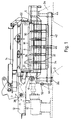
- the roller table illustrated in Figs. 1 and 2 has a rigid base frame 2 comprising opposite side walls 2a spanned by beams 2b. Bearings 6 are provided in the side walls to support rollers 8. The top surfaces of the rollers define a travel path for hot material M longitudinally along the table, perpendicular to the plane of the drawing. The rollers are driven by motors 10 to progress the material along the travel path.
- a rigid structure 12 secured to one side of the base frame 2 carries an upper frame 14 extending over the roller table from which a series of upper heat insulating panels 16 are suspended to cover the table and the hot material M on it.
- Lower heat insulating panels 20 are arranged between the rollers 8 and between the upper and lower panels 16,20 vertical heat insulating panels 22 are mounted on the upper frame 14 to enclose the sides of the material path. All the heat insulating panels may have a thin-walled construction, generally as described in EP 005340, adapted to be heated quickly by the hot material and to radiate heat back to the material.
- the upper frame 14 on which the panels 16 are mounted is pivotable about an axis 26 offset from the side of the roller table and extending longitudinally of the table.
- the pivoting movement swings the panels between the operative position in which they are inoperative position (shown in Fig. 6) lying at a steeply inclined angle to one side of the table, in the manner described in EP 005340 which also illustrates the driver means for the displacement of the upper frame.
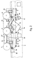
- the lower panels 20 are arranged as a series of similar laterally extending groups of narrow panels spaced across the width of the roller table. Successive panels of each group are separated by protective carry-over or bumper bars 30 which project closer to the material path than the panels so as to be able to deflect distorted material away from contact with the easily damaged panels.
- Each panel is supported on a pair of cranked arms 32 and the arms of each group of panels are connected by a laterally extending tie member 34.
- the ends of the arms 32 remote from the panels 20 are attached by pivot axle 36 to a fixed support 38 running along the length of the table.
- a torque tube 42 is mounted in bearings 44 at the bottom of the base frame 2 and is connected to a motor 52.
- An arm 46 fixed to the torque tube is pivoted to links 48 (not shown in full) that extend in parallel horizontally along the table and are connected by pivots 50 to each laterally extending group of panels 20.
- links 48 not shown in full
- pivots 50 to each laterally extending group of panels 20.
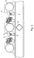
- the distance between adjacent rollers 8 is occupied by pairs of heat insulating panels 60,62, consisting of a larger panel 60 mounted on the cranked arms 32, as before, and an auxiliary fixed panel 62 fitting closely to it, so that there is an equal narrow gap between each roller and the combined panels 60,62 in the operative position.
- the junction face between the main and auxiliary panels is inclined so that the gap between them can be reduced, or even eliminated in the operative position, without the risk of a clash when the displaceable main panels 60 move about their pivot axes 36.
- the panel top faces 70' lie at a moderate inclination in the operative position and are tilted to increase that inclination when they are lowered.
- the inclination In the operative position the inclination is sufficiently small for re-radiation of heat to the hot material on the roller table but it allows at least some of the foreign matter settling on the panels to slide off them, so that the radiation efficiency of the panel can be maintained.
- a gap is provided between the panels of each pair for the this purpose. In a high tonnage rolling mill a substantial quantity of scale can fall onto the panels below the material path. The self-cleaning action of the inclined upper faces thus helps to preserve the efficiency of the panels and whenever more positive clearance of any scale is required the panels can be tilted to their non-operative positions.
- roller tables with closely pitched rollers eg. 900mm
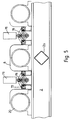
- the pitch of the rollers can be increased, for example, a roller table following a slab caster may have a roller pitch some 50% greater. In that case, from the point of view of conserving heat in the material on the roller table there is less need to contour the panels to fit closely to the rollers and an arrangement of rectangular panels can be deployed in the manner shown in Fig. 6.
- pairs of panels 82 are provided between successive rollers.
- the panels are mounted at opposite sides of the roller table on pivots 84 that extend in the direction of material path and so are able to swing down to the inoperative positions indicated by the reference 82'.
- the means of displacement of the panels between the operative and inoperative positions are not shown but may be analogous to the actuator means described in the earlier examples. Other features of those earlier examples, such as the bumper bars, can of course also be incorporated in this embodiment.
- Roller tables used with slab casters generally are required to have a cut-off torch travel along them to cut the slabs to length. This results in slag adhesion to the rolls, which must be removed, and because of the manner in which the panels can be lowered in the example of Fig. 6, clear of the rolls, such maintenance work is facilitated. It is also possible to lower the panels sequentially along the length of the table during the operation of the cut-off torch to avoid them being damaged by the torch flame.
Landscapes
- Engineering & Computer Science (AREA)
- Mechanical Engineering (AREA)
- Chemical & Material Sciences (AREA)
- General Engineering & Computer Science (AREA)
- Organic Chemistry (AREA)
- Crystallography & Structural Chemistry (AREA)
- Materials Engineering (AREA)
- Metallurgy (AREA)
- Thermal Sciences (AREA)
- Physics & Mathematics (AREA)
- Heat Treatments In General, Especially Conveying And Cooling (AREA)
- Rolls And Other Rotary Bodies (AREA)
- Lining Or Joining Of Plastics Or The Like (AREA)
- Thermal Insulation (AREA)
- Rollers For Roller Conveyors For Transfer (AREA)
- Tunnel Furnaces (AREA)
Applications Claiming Priority (2)
| Application Number | Priority Date | Filing Date | Title |
|---|---|---|---|
| GB9407566A GB9407566D0 (en) | 1994-04-12 | 1994-04-12 | Heat shields for rolling shields |
| GB9407566 | 1994-04-12 |
Publications (3)
| Publication Number | Publication Date |
|---|---|
| EP0677337A2 true EP0677337A2 (de) | 1995-10-18 |
| EP0677337A3 EP0677337A3 (de) | 1996-02-28 |
| EP0677337B1 EP0677337B1 (de) | 1998-07-01 |
Family
ID=10753638
Family Applications (1)
| Application Number | Title | Priority Date | Filing Date |
|---|---|---|---|
| EP95302324A Expired - Lifetime EP0677337B1 (de) | 1994-04-12 | 1995-04-07 | Hitzeschilde für Walzentische |
Country Status (10)
| Country | Link |
|---|---|
| US (1) | US5711175A (de) |
| EP (1) | EP0677337B1 (de) |
| KR (1) | KR100321506B1 (de) |
| AT (1) | ATE167819T1 (de) |
| BR (1) | BR9501363A (de) |
| DE (1) | DE69503168T2 (de) |
| ES (1) | ES2120681T3 (de) |
| GB (1) | GB9407566D0 (de) |
| IN (1) | IN182418B (de) |
| TW (1) | TW272151B (de) |
Cited By (3)
| Publication number | Priority date | Publication date | Assignee | Title |
|---|---|---|---|---|
| EP0744229A1 (de) * | 1995-05-26 | 1996-11-27 | Encomech Engineering Services Limited | Wärmeschilde |
| EP0857523A1 (de) * | 1997-01-28 | 1998-08-12 | Encomech Engineering Services Limited | Verfahren und Vorrichtung zur Temperaturkontrolle |
| WO2000054901A1 (en) * | 1999-03-15 | 2000-09-21 | Encomech Engineering Services Ltd. | Heat shields |
Families Citing this family (10)
| Publication number | Priority date | Publication date | Assignee | Title |
|---|---|---|---|---|
| KR100775231B1 (ko) | 2006-09-01 | 2007-11-12 | 주식회사 포스코 | 압연시 후판재의 선단부 휨 제어장치 및 방법 |
| IT1400003B1 (it) * | 2010-05-18 | 2013-05-09 | Danieli Off Mecc | Dispositivo di colata continua e relativo procedimento |
| CN102125932B (zh) * | 2010-12-16 | 2012-11-07 | 重庆研镁科技有限公司 | 一种镁合金热轧装置及轧制加热的方法 |
| GB2506395A (en) * | 2012-09-28 | 2014-04-02 | Siemens Plc | Roller table and method of rolling a Material |
| DE102013219507A1 (de) | 2013-05-03 | 2014-11-06 | Sms Siemag Aktiengesellschaft | Warmwalzwerk |
| JP6171834B2 (ja) * | 2013-10-21 | 2017-08-02 | Jfeスチール株式会社 | 厚肉鋼材製造用装置列 |
| CN105251782B (zh) * | 2015-11-17 | 2018-04-24 | 北京恩吉节能科技有限公司 | 热轧板坯用保温系统 |
| DE102016217720A1 (de) | 2016-09-16 | 2018-03-22 | Sms Group Gmbh | Verfahrbarer Wärmedämmwagen bei der Metallbearbeitung |
| DE102018219927A1 (de) * | 2018-07-30 | 2020-01-30 | Sms Group Gmbh | Rollenherdofen |
| CN109794519B (zh) * | 2018-12-25 | 2025-12-30 | 柳州钢铁股份有限公司 | 井堆货位与顶部自复位侧面平开保温盖式组合保温装置 |
Family Cites Families (8)
| Publication number | Priority date | Publication date | Assignee | Title |
|---|---|---|---|---|
| CA887953A (en) * | 1971-12-14 | The Steel Company Of Canada | Hot strip mill | |
| GB1040420A (en) * | 1963-11-19 | 1966-08-24 | United Eng Foundry Co | Method and apparatus for controlling the temperature of hot strip |
| CA889615A (en) * | 1963-11-23 | 1972-01-04 | Canadian General Electric Company | Heat reflectors on apparatus for rolling hot metal |
| US4452587A (en) * | 1977-05-04 | 1984-06-05 | Laws William R | Heat shield; and insulation panels therefor |
| US4343168A (en) * | 1977-05-04 | 1982-08-10 | Laws William R | Heat shield arrangements for a rolling mill |
| EP0049000B1 (de) * | 1978-04-27 | 1985-08-21 | Encomech Engineering Services Limited | Hitzeschild für Walzwerke |
| GB8428129D0 (en) * | 1984-11-07 | 1984-12-12 | Encomech Eng Services | Heat retaining means |
| US5101652A (en) * | 1990-07-26 | 1992-04-07 | Allegheny Ludlum Corporation | Insulating heat retention system and method |
-
1994
- 1994-04-12 GB GB9407566A patent/GB9407566D0/en active Pending
-
1995
- 1995-04-01 TW TW084103215A patent/TW272151B/zh not_active IP Right Cessation
- 1995-04-05 IN IN379CA1995 patent/IN182418B/en unknown
- 1995-04-07 ES ES95302324T patent/ES2120681T3/es not_active Expired - Lifetime
- 1995-04-07 EP EP95302324A patent/EP0677337B1/de not_active Expired - Lifetime
- 1995-04-07 AT AT95302324T patent/ATE167819T1/de not_active IP Right Cessation
- 1995-04-07 DE DE69503168T patent/DE69503168T2/de not_active Expired - Fee Related
- 1995-04-11 KR KR1019950008317A patent/KR100321506B1/ko not_active Expired - Lifetime
- 1995-04-12 BR BR9501363A patent/BR9501363A/pt not_active IP Right Cessation
-
1997
- 1997-03-03 US US08/804,293 patent/US5711175A/en not_active Expired - Lifetime
Cited By (6)
| Publication number | Priority date | Publication date | Assignee | Title |
|---|---|---|---|---|
| EP0744229A1 (de) * | 1995-05-26 | 1996-11-27 | Encomech Engineering Services Limited | Wärmeschilde |
| US5699694A (en) * | 1995-05-26 | 1997-12-23 | Encomech Engineering Services Ltd. | Heat shields |
| EP0857523A1 (de) * | 1997-01-28 | 1998-08-12 | Encomech Engineering Services Limited | Verfahren und Vorrichtung zur Temperaturkontrolle |
| US5960663A (en) * | 1997-01-28 | 1999-10-05 | Encomech Engineering Services Ltd | Method and means of temperature control |
| KR100314381B1 (ko) * | 1997-01-28 | 2001-12-28 | 윌리엄 로버트 로우즈 | 롤러테이블및롤러테이블에서고온재료를이동시키는방법 |
| WO2000054901A1 (en) * | 1999-03-15 | 2000-09-21 | Encomech Engineering Services Ltd. | Heat shields |
Also Published As
| Publication number | Publication date |
|---|---|
| DE69503168T2 (de) | 1998-12-17 |
| KR100321506B1 (ko) | 2002-07-18 |
| TW272151B (de) | 1996-03-11 |
| IN182418B (de) | 1999-04-10 |
| US5711175A (en) | 1998-01-27 |
| DE69503168D1 (de) | 1998-08-06 |
| ATE167819T1 (de) | 1998-07-15 |
| EP0677337A3 (de) | 1996-02-28 |
| BR9501363A (pt) | 1995-12-12 |
| ES2120681T3 (es) | 1998-11-01 |
| KR950033229A (ko) | 1995-12-22 |
| EP0677337B1 (de) | 1998-07-01 |
| GB9407566D0 (en) | 1994-06-08 |
Similar Documents
| Publication | Publication Date | Title |
|---|---|---|
| EP0677337B1 (de) | Hitzeschilde für Walzentische | |
| EP0048503B1 (de) | Hitzeschild für band- oder knüppelförmiges Material | |
| US4499746A (en) | Heat shield arrangements for a rolling mill | |
| US4343168A (en) | Heat shield arrangements for a rolling mill | |
| AU705503B2 (en) | Heat shields for roller tables | |
| EP0857523B1 (de) | Verfahren und Vorrichtung zur Temperaturkontrolle | |
| EP0198595B1 (de) | Anordnungen von Hitzeschilden | |
| US4648837A (en) | Walking beam furnace | |
| US4554812A (en) | Heat shield for a rolling mill | |
| KR102551750B1 (ko) | 롤러 테이블 장치 | |
| EP1177055B1 (de) | Hitzeschilder | |
| GB1603427A (en) | Heat shield arrangements | |
| US5848543A (en) | Strip mill with movable coiling furnace | |
| GB2075937A (en) | A car for transferring hot metal workpieces | |
| EP3858504B1 (de) | Wärmerückhaltende walzausrüstung | |
| RU2138349C1 (ru) | Подъемный стол | |
| WO2014048629A1 (en) | Roller table and method of rolling a material | |
| MXPA00004549A (en) | Method to control the axial position of slabs emerging from continuous casting and relative device | |
| JPH01150405A (ja) | 圧延機 |
Legal Events
| Date | Code | Title | Description |
|---|---|---|---|
| PUAI | Public reference made under article 153(3) epc to a published international application that has entered the european phase |
Free format text: ORIGINAL CODE: 0009012 |
|
| AK | Designated contracting states |
Kind code of ref document: A2 Designated state(s): AT BE DE ES FR GB IT |
|
| PUAL | Search report despatched |
Free format text: ORIGINAL CODE: 0009013 |
|
| AK | Designated contracting states |
Kind code of ref document: A3 Designated state(s): AT BE DE ES FR GB IT |
|
| 17P | Request for examination filed |
Effective date: 19960816 |
|
| GRAG | Despatch of communication of intention to grant |
Free format text: ORIGINAL CODE: EPIDOS AGRA |
|
| 17Q | First examination report despatched |
Effective date: 19970728 |
|
| GRAG | Despatch of communication of intention to grant |
Free format text: ORIGINAL CODE: EPIDOS AGRA |
|
| GRAG | Despatch of communication of intention to grant |
Free format text: ORIGINAL CODE: EPIDOS AGRA |
|
| GRAH | Despatch of communication of intention to grant a patent |
Free format text: ORIGINAL CODE: EPIDOS IGRA |
|
| GRAH | Despatch of communication of intention to grant a patent |
Free format text: ORIGINAL CODE: EPIDOS IGRA |
|
| GRAA | (expected) grant |
Free format text: ORIGINAL CODE: 0009210 |
|
| AK | Designated contracting states |
Kind code of ref document: B1 Designated state(s): AT BE DE ES FR GB IT |
|
| REF | Corresponds to: |
Ref document number: 167819 Country of ref document: AT Date of ref document: 19980715 Kind code of ref document: T |
|
| REF | Corresponds to: |
Ref document number: 69503168 Country of ref document: DE Date of ref document: 19980806 |
|
| ET | Fr: translation filed | ||
| REG | Reference to a national code |
Ref country code: ES Ref legal event code: FG2A Ref document number: 2120681 Country of ref document: ES Kind code of ref document: T3 |
|
| K2C3 | Correction of patent specification (complete document) published |
Effective date: 19980701 |
|
| PLBE | No opposition filed within time limit |
Free format text: ORIGINAL CODE: 0009261 |
|
| STAA | Information on the status of an ep patent application or granted ep patent |
Free format text: STATUS: NO OPPOSITION FILED WITHIN TIME LIMIT |
|
| 26N | No opposition filed | ||
| REG | Reference to a national code |
Ref country code: GB Ref legal event code: IF02 |
|
| PGFP | Annual fee paid to national office [announced via postgrant information from national office to epo] |
Ref country code: AT Payment date: 20030423 Year of fee payment: 9 |
|
| PG25 | Lapsed in a contracting state [announced via postgrant information from national office to epo] |
Ref country code: AT Free format text: LAPSE BECAUSE OF NON-PAYMENT OF DUE FEES Effective date: 20040407 |
|
| PGFP | Annual fee paid to national office [announced via postgrant information from national office to epo] |
Ref country code: ES Payment date: 20060322 Year of fee payment: 12 |
|
| PGFP | Annual fee paid to national office [announced via postgrant information from national office to epo] |
Ref country code: GB Payment date: 20060420 Year of fee payment: 12 |
|
| PGFP | Annual fee paid to national office [announced via postgrant information from national office to epo] |
Ref country code: FR Payment date: 20060424 Year of fee payment: 12 |
|
| PGFP | Annual fee paid to national office [announced via postgrant information from national office to epo] |
Ref country code: DE Payment date: 20060427 Year of fee payment: 12 Ref country code: BE Payment date: 20060427 Year of fee payment: 12 |
|
| PGFP | Annual fee paid to national office [announced via postgrant information from national office to epo] |
Ref country code: IT Payment date: 20060430 Year of fee payment: 12 |
|
| GBPC | Gb: european patent ceased through non-payment of renewal fee |
Effective date: 20070407 |
|
| BERE | Be: lapsed |
Owner name: *ENCOMECH ENGINEERING SERVICES LTD Effective date: 20070430 |
|
| PG25 | Lapsed in a contracting state [announced via postgrant information from national office to epo] |
Ref country code: DE Free format text: LAPSE BECAUSE OF NON-PAYMENT OF DUE FEES Effective date: 20071101 |
|
| PG25 | Lapsed in a contracting state [announced via postgrant information from national office to epo] |
Ref country code: BE Free format text: LAPSE BECAUSE OF NON-PAYMENT OF DUE FEES Effective date: 20070430 |
|
| PG25 | Lapsed in a contracting state [announced via postgrant information from national office to epo] |
Ref country code: GB Free format text: LAPSE BECAUSE OF NON-PAYMENT OF DUE FEES Effective date: 20070407 |
|
| REG | Reference to a national code |
Ref country code: ES Ref legal event code: FD2A Effective date: 20070409 |
|
| PG25 | Lapsed in a contracting state [announced via postgrant information from national office to epo] |
Ref country code: FR Free format text: LAPSE BECAUSE OF NON-PAYMENT OF DUE FEES Effective date: 20070430 |
|
| PG25 | Lapsed in a contracting state [announced via postgrant information from national office to epo] |
Ref country code: ES Free format text: LAPSE BECAUSE OF NON-PAYMENT OF DUE FEES Effective date: 20070409 |
|
| PG25 | Lapsed in a contracting state [announced via postgrant information from national office to epo] |
Ref country code: IT Free format text: LAPSE BECAUSE OF NON-PAYMENT OF DUE FEES Effective date: 20070407 |