EP0677337A2 - Heat shields for roller tables - Google Patents
Heat shields for roller tables Download PDFInfo
- Publication number
- EP0677337A2 EP0677337A2 EP95302324A EP95302324A EP0677337A2 EP 0677337 A2 EP0677337 A2 EP 0677337A2 EP 95302324 A EP95302324 A EP 95302324A EP 95302324 A EP95302324 A EP 95302324A EP 0677337 A2 EP0677337 A2 EP 0677337A2
- Authority
- EP
- European Patent Office
- Prior art keywords
- panels
- panel
- path
- arrangement according
- heat
- Prior art date
- Legal status (The legal status is an assumption and is not a legal conclusion. Google has not performed a legal analysis and makes no representation as to the accuracy of the status listed.)
- Granted
Links
- PEXCHERCCDRZCY-UHFFFAOYSA-N CC1=C=C=C=CC1C[N+]([O-])=O Chemical compound CC1=C=C=C=CC1C[N+]([O-])=O PEXCHERCCDRZCY-UHFFFAOYSA-N 0.000 description 1
Images


Classifications
-
- F—MECHANICAL ENGINEERING; LIGHTING; HEATING; WEAPONS; BLASTING
- F27—FURNACES; KILNS; OVENS; RETORTS
- F27D—DETAILS OR ACCESSORIES OF FURNACES, KILNS, OVENS, OR RETORTS, IN SO FAR AS THEY ARE OF KINDS OCCURRING IN MORE THAN ONE KIND OF FURNACE
- F27D3/00—Charging; Discharging; Manipulation of charge
- F27D3/0024—Charging; Discharging; Manipulation of charge of metallic workpieces
-
- B—PERFORMING OPERATIONS; TRANSPORTING
- B21—MECHANICAL METAL-WORKING WITHOUT ESSENTIALLY REMOVING MATERIAL; PUNCHING METAL
- B21B—ROLLING OF METAL
- B21B45/00—Devices for surface or other treatment of work, specially combined with or arranged in, or specially adapted for use in connection with, metal-rolling mills
- B21B45/008—Heat shields
-
- B—PERFORMING OPERATIONS; TRANSPORTING
- B21—MECHANICAL METAL-WORKING WITHOUT ESSENTIALLY REMOVING MATERIAL; PUNCHING METAL
- B21B—ROLLING OF METAL
- B21B39/00—Arrangements for moving, supporting, or positioning work, or controlling its movement, combined with or arranged in, or specially adapted for use in connection with, metal-rolling mills
- B21B39/02—Feeding or supporting work; Braking or tensioning arrangements, e.g. threading arrangements
- B21B39/12—Arrangement or installation of roller tables in relation to a roll stand
-
- C—CHEMISTRY; METALLURGY
- C21—METALLURGY OF IRON
- C21D—MODIFYING THE PHYSICAL STRUCTURE OF FERROUS METALS; GENERAL DEVICES FOR HEAT TREATMENT OF FERROUS OR NON-FERROUS METALS OR ALLOYS; MAKING METAL MALLEABLE, e.g. BY DECARBURISATION OR TEMPERING
- C21D9/00—Heat treatment, e.g. annealing, hardening, quenching or tempering, adapted for particular articles; Furnaces therefor
- C21D9/0006—Details, accessories not peculiar to any of the following furnaces
-
- F—MECHANICAL ENGINEERING; LIGHTING; HEATING; WEAPONS; BLASTING
- F27—FURNACES; KILNS; OVENS; RETORTS
- F27D—DETAILS OR ACCESSORIES OF FURNACES, KILNS, OVENS, OR RETORTS, IN SO FAR AS THEY ARE OF KINDS OCCURRING IN MORE THAN ONE KIND OF FURNACE
- F27D3/00—Charging; Discharging; Manipulation of charge
- F27D3/02—Skids or tracks for heavy objects
- F27D3/026—Skids or tracks for heavy objects transport or conveyor rolls for furnaces; roller rails
-
- F—MECHANICAL ENGINEERING; LIGHTING; HEATING; WEAPONS; BLASTING
- F27—FURNACES; KILNS; OVENS; RETORTS
- F27D—DETAILS OR ACCESSORIES OF FURNACES, KILNS, OVENS, OR RETORTS, IN SO FAR AS THEY ARE OF KINDS OCCURRING IN MORE THAN ONE KIND OF FURNACE
- F27D3/00—Charging; Discharging; Manipulation of charge
- F27D2003/0034—Means for moving, conveying, transporting the charge in the furnace or in the charging facilities
- F27D2003/0042—Means for moving, conveying, transporting the charge in the furnace or in the charging facilities comprising roller trains
-
- Y—GENERAL TAGGING OF NEW TECHNOLOGICAL DEVELOPMENTS; GENERAL TAGGING OF CROSS-SECTIONAL TECHNOLOGIES SPANNING OVER SEVERAL SECTIONS OF THE IPC; TECHNICAL SUBJECTS COVERED BY FORMER USPC CROSS-REFERENCE ART COLLECTIONS [XRACs] AND DIGESTS
- Y02—TECHNOLOGIES OR APPLICATIONS FOR MITIGATION OR ADAPTATION AGAINST CLIMATE CHANGE
- Y02P—CLIMATE CHANGE MITIGATION TECHNOLOGIES IN THE PRODUCTION OR PROCESSING OF GOODS
- Y02P70/00—Climate change mitigation technologies in the production process for final industrial or consumer products
- Y02P70/10—Greenhouse gas [GHG] capture, material saving, heat recovery or other energy efficient measures, e.g. motor control, characterised by manufacturing processes, e.g. for rolling metal or metal working
Definitions
- This invention relates to arrangements of heat shields for roller tables, in particular roller tables for transporting material in hot rolling mills or steel casting plant, but it may also be applicable to other roller tables for handling hot material in slab or strip form.
- EP 005340 also illustrates how the heat insulating panels disposed over the hot material path can be mounted on a frame pivoted on a longitudinal axis offset away from one side of the roller table so that in this case they can pivoted upwards clear of the roller table to leave the material exposed and so cooled by radiation.
- a heat shielding arrangement for hot material on a roller table comprises a plurality of heat insulating panels disposed below a material path provided by the rollers of the table and between successive rollers said panels being displaceably mounted to be movable between a raised operative position close to the hot material path and a lower inoperative position in which the panel upper faces are retracted away from said path.
- the rollers are displaceable on pivot mountings having axes generally parallel to the axes of the rollers.
- the pivot axes extend longitudinally of the roller table, e.g. opposed pairs of panels are arranged between successive rollers, mounted on respective longitudinal pivot axes at opposite sides of the roller table to extend towards each other from said opposite sides.
- the pivot axis of each panel is offset from the panel to be located underneath a first of the two successive rollers between which the panel is disposed and close to the periphery of said one roller.
- the initial pivoting of the panels can displace them in a direction approaching the vertical, thereby to reduce the clearance that must be left to allow them to clear the other of the pair of rollers between which they lie.
- a fixed auxiliary heat insulating panel may be disposed adjacent each displaceable panel, between that panel and said other roller of the pair, to extend the area shielded in the space between successive rollers.
- Such fixed auxiliary heat insulating panels may be disposed close to one or both rollers of a pair of successive rollers. Although they will reduce the possible rate of heat loss from the hot material path, they will continue to shield the rollers from radiant heat when the main panel is lowered. Similar auxiliary heat insulating panels may be adopted when the displaceable panels are mounted on longitudinal pivot axes.
- the panels In their operative positions, the panels may extend generally parallel to said material path to re-radiating heat from the material on said path back to said material. It may be desirable, however, to give the top faces of each panel a moderate inclination in its operative position, in order to assist the clearance of foreign matter, such as mill scale, falling on those faces. In that case, if the panels are pivotally mounted, said inclination of each said panel top face is preferably in the direction of downward tilting of the panel.
- Rigid protective elements can be arranged in fixed locations close to the panels to protect them against damage by material running along the hot material path, the tops of said elements lying between the plane of said path and the top faces of the panels in their operative positions.
- An arrangement according to the invention preferably also has a plurality of heat insulating panels above the hot material path which can be moved away from the path to allow heat loss similarly by radiation from the upper surfaces of the material.
- the employment of both upper and lower heat insulating panels which can be displaced to and from positions allowing a substantially increased rate of heat loss from hot material between them is of particular advantage in the working of thicker materials. For example, it been found that when the known arrangement of displaceable upper panels in a rolling mill is used, as the thickness of the material increases a difference can arise between the temperatures and the top and bottom surfaces of the material which is sufficiently large to affect the quality of the final rolled product. By allowing radiation heat loss from both faces of the material, this unwanted effect can be avoided or substantially reduced.
- Heat sensing means may be provided to control the displacement of panels.
- a common heat sensing means conveniently located with the upper panels, can be arranged to control the displacement of both series of panels.
- the roller table illustrated in Figs. 1 and 2 has a rigid base frame 2 comprising opposite side walls 2a spanned by beams 2b. Bearings 6 are provided in the side walls to support rollers 8. The top surfaces of the rollers define a travel path for hot material M longitudinally along the table, perpendicular to the plane of the drawing. The rollers are driven by motors 10 to progress the material along the travel path.
- a rigid structure 12 secured to one side of the base frame 2 carries an upper frame 14 extending over the roller table from which a series of upper heat insulating panels 16 are suspended to cover the table and the hot material M on it.
- Lower heat insulating panels 20 are arranged between the rollers 8 and between the upper and lower panels 16,20 vertical heat insulating panels 22 are mounted on the upper frame 14 to enclose the sides of the material path. All the heat insulating panels may have a thin-walled construction, generally as described in EP 005340, adapted to be heated quickly by the hot material and to radiate heat back to the material.
- the upper frame 14 on which the panels 16 are mounted is pivotable about an axis 26 offset from the side of the roller table and extending longitudinally of the table.
- the pivoting movement swings the panels between the operative position in which they are inoperative position (shown in Fig. 6) lying at a steeply inclined angle to one side of the table, in the manner described in EP 005340 which also illustrates the driver means for the displacement of the upper frame.
- the lower panels 20 are arranged as a series of similar laterally extending groups of narrow panels spaced across the width of the roller table. Successive panels of each group are separated by protective carry-over or bumper bars 30 which project closer to the material path than the panels so as to be able to deflect distorted material away from contact with the easily damaged panels.
- Each panel is supported on a pair of cranked arms 32 and the arms of each group of panels are connected by a laterally extending tie member 34.
- the ends of the arms 32 remote from the panels 20 are attached by pivot axle 36 to a fixed support 38 running along the length of the table.
- a torque tube 42 is mounted in bearings 44 at the bottom of the base frame 2 and is connected to a motor 52.
- An arm 46 fixed to the torque tube is pivoted to links 48 (not shown in full) that extend in parallel horizontally along the table and are connected by pivots 50 to each laterally extending group of panels 20.
- links 48 not shown in full
- pivots 50 to each laterally extending group of panels 20.
- the distance between adjacent rollers 8 is occupied by pairs of heat insulating panels 60,62, consisting of a larger panel 60 mounted on the cranked arms 32, as before, and an auxiliary fixed panel 62 fitting closely to it, so that there is an equal narrow gap between each roller and the combined panels 60,62 in the operative position.
- the junction face between the main and auxiliary panels is inclined so that the gap between them can be reduced, or even eliminated in the operative position, without the risk of a clash when the displaceable main panels 60 move about their pivot axes 36.
- the panel top faces 70' lie at a moderate inclination in the operative position and are tilted to increase that inclination when they are lowered.
- the inclination In the operative position the inclination is sufficiently small for re-radiation of heat to the hot material on the roller table but it allows at least some of the foreign matter settling on the panels to slide off them, so that the radiation efficiency of the panel can be maintained.
- a gap is provided between the panels of each pair for the this purpose. In a high tonnage rolling mill a substantial quantity of scale can fall onto the panels below the material path. The self-cleaning action of the inclined upper faces thus helps to preserve the efficiency of the panels and whenever more positive clearance of any scale is required the panels can be tilted to their non-operative positions.
- roller tables with closely pitched rollers eg. 900mm
- the pitch of the rollers can be increased, for example, a roller table following a slab caster may have a roller pitch some 50% greater. In that case, from the point of view of conserving heat in the material on the roller table there is less need to contour the panels to fit closely to the rollers and an arrangement of rectangular panels can be deployed in the manner shown in Fig. 6.
- pairs of panels 82 are provided between successive rollers.
- the panels are mounted at opposite sides of the roller table on pivots 84 that extend in the direction of material path and so are able to swing down to the inoperative positions indicated by the reference 82'.
- the means of displacement of the panels between the operative and inoperative positions are not shown but may be analogous to the actuator means described in the earlier examples. Other features of those earlier examples, such as the bumper bars, can of course also be incorporated in this embodiment.
- Roller tables used with slab casters generally are required to have a cut-off torch travel along them to cut the slabs to length. This results in slag adhesion to the rolls, which must be removed, and because of the manner in which the panels can be lowered in the example of Fig. 6, clear of the rolls, such maintenance work is facilitated. It is also possible to lower the panels sequentially along the length of the table during the operation of the cut-off torch to avoid them being damaged by the torch flame.
Abstract
Description
- This invention relates to arrangements of heat shields for roller tables, in particular roller tables for transporting material in hot rolling mills or steel casting plant, but it may also be applicable to other roller tables for handling hot material in slab or strip form.
- It is known to provide heat insulating means around the path of hot material in slab or strip form being worked in a hot rolling mill, as illustrated in EP 005340, for example. By reducing the loss of heat between stages of working the material, it is possible to increase the efficiency of operation and the quality of the final product.
- In some circumstances, however, the material may be hotter than is required for the following stage of its processing yet it is not practical to limit its temperature before it leaves the preceding stage, for example, when transferring a short product run to a finishing mill. EP 005340 also illustrates how the heat insulating panels disposed over the hot material path can be mounted on a frame pivoted on a longitudinal axis offset away from one side of the roller table so that in this case they can pivoted upwards clear of the roller table to leave the material exposed and so cooled by radiation.
- According to the present invention, a heat shielding arrangement for hot material on a roller table comprises a plurality of heat insulating panels disposed below a material path provided by the rollers of the table and between successive rollers said panels being displaceably mounted to be movable between a raised operative position close to the hot material path and a lower inoperative position in which the panel upper faces are retracted away from said path.
- The ability to allow heat radiation downwards is limited by the structure of the conventional roller table which does not permit the lower panels to be swung away from the table and the space below the rollers is in any case limited. It has been found, however, that moving the panels further from the hot material path allows a significantly greater heat loss from that region. In particular, if the panels between successive rollers are pivotally displaceable within the width of the roller table their insulating effect can be substantially reduced because the inclination of the hot surfaces of the panels previously facing the hot material path reduces the re-radiation of heat back to said path.
- In one form of the invention, the rollers are displaceable on pivot mountings having axes generally parallel to the axes of the rollers. In another form the pivot axes extend longitudinally of the roller table, e.g. opposed pairs of panels are arranged between successive rollers, mounted on respective longitudinal pivot axes at opposite sides of the roller table to extend towards each other from said opposite sides.
- In a preferred arrangement of panels pivoting on axes generally parallel to the roller axes, the pivot axis of each panel is offset from the panel to be located underneath a first of the two successive rollers between which the panel is disposed and close to the periphery of said one roller. In this way, the initial pivoting of the panels can displace them in a direction approaching the vertical, thereby to reduce the clearance that must be left to allow them to clear the other of the pair of rollers between which they lie. To reduce heat loss when the lower panels are in their operative positions, a fixed auxiliary heat insulating panel may be disposed adjacent each displaceable panel, between that panel and said other roller of the pair, to extend the area shielded in the space between successive rollers.
- Such fixed auxiliary heat insulating panels may be disposed close to one or both rollers of a pair of successive rollers. Although they will reduce the possible rate of heat loss from the hot material path, they will continue to shield the rollers from radiant heat when the main panel is lowered. Similar auxiliary heat insulating panels may be adopted when the displaceable panels are mounted on longitudinal pivot axes.
- In their operative positions, the panels may extend generally parallel to said material path to re-radiating heat from the material on said path back to said material. It may be desirable, however, to give the top faces of each panel a moderate inclination in its operative position, in order to assist the clearance of foreign matter, such as mill scale, falling on those faces. In that case, if the panels are pivotally mounted, said inclination of each said panel top face is preferably in the direction of downward tilting of the panel.
- Rigid protective elements can be arranged in fixed locations close to the panels to protect them against damage by material running along the hot material path, the tops of said elements lying between the plane of said path and the top faces of the panels in their operative positions.
- An arrangement according to the invention preferably also has a plurality of heat insulating panels above the hot material path which can be moved away from the path to allow heat loss similarly by radiation from the upper surfaces of the material. The employment of both upper and lower heat insulating panels which can be displaced to and from positions allowing a substantially increased rate of heat loss from hot material between them is of particular advantage in the working of thicker materials. For example, it been found that when the known arrangement of displaceable upper panels in a rolling mill is used, as the thickness of the material increases a difference can arise between the temperatures and the top and bottom surfaces of the material which is sufficiently large to affect the quality of the final rolled product. By allowing radiation heat loss from both faces of the material, this unwanted effect can be avoided or substantially reduced.
- Heat sensing means may be provided to control the displacement of panels. When both upper and lower series of panels are deployed a common heat sensing means, conveniently located with the upper panels, can be arranged to control the displacement of both series of panels.
- Embodiments of the invention will be described in more detail by way of example, with reference to the accompanying drawings, in which:
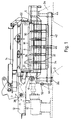
- Fig. 1 is a transverse cross-section of a roller table for a hot rolling mill incorporating a heat shield arrangement according to the invention,
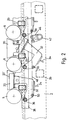
- Fig. 2 is a longitudinal section of a portion of the table in Fig. 1, showing heat insulating panels in their alternative end positions,
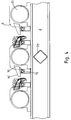
- Fig. 3 is a view similar to Fig. 2 illustrating a modified arrangement of the heat insulating panels,
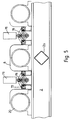
- Figs. 4 and 5 are views similar to Figs. 2 and 3 showing another modified arrangement according to the invention, Fig 4 illustrating the insulating panels and their displaceability and Fig. 5 illustrating their operating mechanism, and
- Fig. 6 is a transverse cross-sectional view of another arrangement according to the invention, showing another arrangement according to the invention, showing also the upper insulating panels of Fig. 1 in their raised position.
- The roller table illustrated in Figs. 1 and 2 has a
rigid base frame 2 comprisingopposite side walls 2a spanned bybeams 2b.Bearings 6 are provided in the side walls to support rollers 8. The top surfaces of the rollers define a travel path for hot material M longitudinally along the table, perpendicular to the plane of the drawing. The rollers are driven bymotors 10 to progress the material along the travel path. Arigid structure 12 secured to one side of thebase frame 2 carries anupper frame 14 extending over the roller table from which a series of upperheat insulating panels 16 are suspended to cover the table and the hot material M on it. Lowerheat insulating panels 20 are arranged between the rollers 8 and between the upper andlower panels heat insulating panels 22 are mounted on theupper frame 14 to enclose the sides of the material path. All the heat insulating panels may have a thin-walled construction, generally as described in EP 005340, adapted to be heated quickly by the hot material and to radiate heat back to the material. - The
upper frame 14 on which thepanels 16 are mounted is pivotable about anaxis 26 offset from the side of the roller table and extending longitudinally of the table. The pivoting movement swings the panels between the operative position in which they are inoperative position (shown in Fig. 6) lying at a steeply inclined angle to one side of the table, in the manner described in EP 005340 which also illustrates the driver means for the displacement of the upper frame. - The
lower panels 20 are arranged as a series of similar laterally extending groups of narrow panels spaced across the width of the roller table. Successive panels of each group are separated by protective carry-over orbumper bars 30 which project closer to the material path than the panels so as to be able to deflect distorted material away from contact with the easily damaged panels. Each panel is supported on a pair of crankedarms 32 and the arms of each group of panels are connected by a laterally extendingtie member 34. For each group of panels, the ends of thearms 32 remote from thepanels 20 are attached bypivot axle 36 to afixed support 38 running along the length of the table. - Each group of
panels 20 therefore swings as a unit on itspivot axle 36, between the operative position shown to the left in Fig. 2, in which the upper faces 20' of the panels are close and parallel to the hot material path to reflect back heat radiated from the hot material, and the inoperative position, shown to the right in Fig. 2, in which the panels are lowered and tilted at an angle of about 30° away from the hot material path, so that they no longer act to maintain the temperature of the hot material. The tilting of the panels also allows any scale that may have collected on their top faces to fall from them and be removed through the roller table flume (not shown). - To displace the panels, a
torque tube 42 is mounted inbearings 44 at the bottom of thebase frame 2 and is connected to amotor 52. Anarm 46 fixed to the torque tube is pivoted to links 48 (not shown in full) that extend in parallel horizontally along the table and are connected bypivots 50 to each laterally extending group ofpanels 20. When thetorque tube 42 is rotated by the motor, therefore, the groups of panels tilt in unison between the alternative positions shown in Fig. 2. As the positions of thearm 46 in Fig. 2 also illustrate, a small rotation of the torque tube is sufficient to move the panels to their inoperative position, so that they can react rapidly when actuated. - The location of the
pivot axle 36 of each group of panels in an offset position below one of the pair of rollers between which the group of panels is located, gives the initial downward movement of the panels a direction close to the vertical. It is still necessary to provide some clearance for the movement of the panels, however and Fig. 2 indicates that there is a larger gap between panel and roller to one side of the panels than the other. This may not be significant in some installations where the length of the roller table is such that it is not necessary to provide lower heat insulating panels over the full length of the table. The reduced efficiency of insulation resulting from the reduced efficiency of insulation resulting from the shorter panels can then be compensated by deploying the panels over a greater proportion of the length of the table. - Where maximum heat insulation effect is required below the hot material path, Fig. 3 illustrates a modification to assist this purpose while employing a displacement mechanism identical to that already described. The modified arrangement is similar in all other respects to the arrangement first described and identical parts are indicated by the same reference numbers.
- In this example, the distance between adjacent rollers 8 is occupied by pairs of
heat insulating panels larger panel 60 mounted on the crankedarms 32, as before, and an auxiliary fixedpanel 62 fitting closely to it, so that there is an equal narrow gap between each roller and the combinedpanels main panels 60 move about theirpivot axes 36. - The inclined free edges at the front and rear of the
lower panels panels 62 maintain this effect when thedisplaceable panels 60 are swung down. If required, the other side of each roller can be similarly protected by relatively narrow fixed insulating panels, as indicated at 62a, so that the displaceable panels occupy a main central region between front and rear auxiliary panels. - In operation, it is of course possible to arrange that the lower panels occupy intermediate positions between the two end positions illustrated in Figs. 2 and 3, for closer control of their insulating effect. Control means for the displacement of the panels are not illustrated in detail, but it can be arranged that the upper and
lower panels - Figs. 4 and 5 illustrate the arrangement of lower panels in a further embodiment of the invention in which parts corresponding to those already described are indicated by the same reference numbers. Groups of
heat insulating panels 70 are mounted onpivot axles 72 extending across the width of the roller table below the hot material path. Between each successive pair ofrollers 20, thepanels 70 are disposed as mirror-image pairs onrespective pivot axles 72 mounted on thebase frame 2. Theaxles 72 are rotated oppositely to each other to displace the panels between operative and inoperative positions, as indicated in Fig. 4. The movement is generated byfluid actuators 76 or the like disposed beyond the width of the roller table on the roll motor drive side. Each actuator is coupled to a pair ofarms 78 secured to therespective pivot axles 72 of the groups of panels between successive rollers. Contraction and extension of theactuators 76 as shown in Fig. 5 displaces the panels in the manner as shown in Fig. 4. - As shown by the right-hand groups of panels in the groups of Fig. 4, the panel top faces 70' lie at a moderate inclination in the operative position and are tilted to increase that inclination when they are lowered. In the operative position the inclination is sufficiently small for re-radiation of heat to the hot material on the roller table but it allows at least some of the foreign matter settling on the panels to slide off them, so that the radiation efficiency of the panel can be maintained. A gap is provided between the panels of each pair for the this purpose. In a high tonnage rolling mill a substantial quantity of scale can fall onto the panels below the material path. The self-cleaning action of the inclined upper faces thus helps to preserve the efficiency of the panels and whenever more positive clearance of any scale is required the panels can be tilted to their non-operative positions.
- It should be noted that although the top faces can be turned through almost 90° to their inoperative position, the oblique side faces opposite the rollers remain at a considerable angle to the material path. They do not have any substantial re-radiating effect therefore when the panels are put in the inoperative position, while in the operative position they are disposed close to the rolls to maximise their shielding effect thereon.
- For simplicity, other features illustrated in the earlier drawings have not been shown in Figs. 4 and 5, such as the bumper bars 30 to protect the panels and the inclusion of upper heat-shielding panels. Also as described earlier, instead of each set of panels between successive rollers having its
own actuator 76, a larger actuator can displace a number of sets of panels through a linkage. - The examples shown so far have roller tables with closely pitched rollers (eg. 900mm), such as are required to support relative thin material such as hot steel strip. If the table is to operate with thicker slabs the pitch of the rollers can be increased, for example, a roller table following a slab caster may have a roller pitch some 50% greater. In that case, from the point of view of conserving heat in the material on the roller table there is less need to contour the panels to fit closely to the rollers and an arrangement of rectangular panels can be deployed in the manner shown in Fig. 6.
- In Fig. 6, in which parts already described are indicated by the same reference numbers again, pairs of
panels 82 are provided between successive rollers. The panels are mounted at opposite sides of the roller table onpivots 84 that extend in the direction of material path and so are able to swing down to the inoperative positions indicated by the reference 82'. The means of displacement of the panels between the operative and inoperative positions are not shown but may be analogous to the actuator means described in the earlier examples. Other features of those earlier examples, such as the bumper bars, can of course also be incorporated in this embodiment. - Roller tables used with slab casters generally are required to have a cut-off torch travel along them to cut the slabs to length. This results in slag adhesion to the rolls, which must be removed, and because of the manner in which the panels can be lowered in the example of Fig. 6, clear of the rolls, such maintenance work is facilitated. It is also possible to lower the panels sequentially along the length of the table during the operation of the cut-off torch to avoid them being damaged by the torch flame.
Claims (12)
- A heat shielding arrangement for hot material on a roller table comprising a plurality of heat insulating panels (20) disposed below a material path provided by the rollers (8) of the table and between successive rollers, characterised in that said lower panels are displaceably mounted to be movable between a raised operative position close to the hot material path and a lower inoperative position in which the panel upper faces (20') are retracted away from said path.
- A heat shield arrangement according to claim 1 wherein the upper faces (20') of the panels which re-radiate heat to the material in the operative position of the panels, are disposed in said inoperative position at an angle to the material path in order to reduce or prevent the reflection of heat to the material on the path.
- A heat shield arrangement according to claim 1 or claim 2 wherein the panels (20) between successive pairs of rollers (8) are displaceable on pivot mountings (32,36) having axes generally parallel to the axes of the rollers.
- A heat shield arrangement according to claim 3 wherein the pivot axis of each panel is offset from the panel to be located underneath a first of the two successive rollers (20) between which the panel is disposed and close to the periphery of said first roller.
- A heat shield arrangement according to claim 1 or claim 2 wherein the panels (82) between successive rollers (8) are displaceable on pivot mountings (84) having axes extending generally in the direction of the hot material path.
- A heat shield arrangement according to claim 5 wherein between successive rollers (8) there are arranged at least one pair of panels (82), mounted on respective pivot mountings (84) at opposite sides of the roller table and extending towards each other from said opposite sides.
- A heat shield arrangement according to any one of the preceding claims wherein the panels (70) have top faces (70') that are inclined to the horizontal in the operative position.
- A heat shield arrangement according to claim 7 when dependent to any one of claims 3 to 6, wherein said inclination of each said panel top face (70') is in the direction of tilting of the panel towards the inoperative position.
- A heat shield arrangement according to any one of the preceding claims wherein adjacent at least one of the pair of successive rollers (20) between which at least one said displaceable panel (60) lies there is a fixed auxiliary heat insulating panel (62) disposed between said displaceable panel and said one roller.
- A heat shield arrangement according to claim 9, wherein the vertical projection of said auxiliary panel (62) overlaps the adjacent side of said one roller (20).
- A heat shield arrangement according to any one of the preceding claims wherein rigid protective elements (30) are arranged in fixed locations close to the panels to protect them against impact by distorted material, the tops of said elements lying between the plane of said hot material path and the top faces of the panels (20) in their operative positions.
- A heat shield arrangement according to any one of the preceding claims further comprising a plurality of heat insulating panels (16) above said hot material path and means for moving the upper panels towards and away from the path to vary their heat insulating effect on hot material on the path, and common heat sensing means (66) are arranged to control said movements of both said pluralities of panels.
Applications Claiming Priority (2)
| Application Number | Priority Date | Filing Date | Title |
|---|---|---|---|
| GB9407566 | 1994-04-12 | ||
| GB9407566A GB9407566D0 (en) | 1994-04-12 | 1994-04-12 | Heat shields for rolling shields |
Publications (3)
| Publication Number | Publication Date |
|---|---|
| EP0677337A2 true EP0677337A2 (en) | 1995-10-18 |
| EP0677337A3 EP0677337A3 (en) | 1996-02-28 |
| EP0677337B1 EP0677337B1 (en) | 1998-07-01 |
Family
ID=10753638
Family Applications (1)
| Application Number | Title | Priority Date | Filing Date |
|---|---|---|---|
| EP95302324A Expired - Lifetime EP0677337B1 (en) | 1994-04-12 | 1995-04-07 | Heat shields for roller tables |
Country Status (10)
| Country | Link |
|---|---|
| US (1) | US5711175A (en) |
| EP (1) | EP0677337B1 (en) |
| KR (1) | KR100321506B1 (en) |
| AT (1) | ATE167819T1 (en) |
| BR (1) | BR9501363A (en) |
| DE (1) | DE69503168T2 (en) |
| ES (1) | ES2120681T3 (en) |
| GB (1) | GB9407566D0 (en) |
| IN (1) | IN182418B (en) |
| TW (1) | TW272151B (en) |
Cited By (3)
| Publication number | Priority date | Publication date | Assignee | Title |
|---|---|---|---|---|
| EP0744229A1 (en) * | 1995-05-26 | 1996-11-27 | Encomech Engineering Services Limited | Heat shields |
| EP0857523A1 (en) * | 1997-01-28 | 1998-08-12 | Encomech Engineering Services Limited | Method and means of temperature control |
| WO2000054901A1 (en) * | 1999-03-15 | 2000-09-21 | Encomech Engineering Services Ltd. | Heat shields |
Families Citing this family (9)
| Publication number | Priority date | Publication date | Assignee | Title |
|---|---|---|---|---|
| KR100775231B1 (en) | 2006-09-01 | 2007-11-12 | 주식회사 포스코 | Apparatus and method for controlling warp of rolled heavy plate |
| IT1400003B1 (en) * | 2010-05-18 | 2013-05-09 | Danieli Off Mecc | CONTINUOUS CASTING DEVICE AND ITS PROCEDURE |
| CN102125932B (en) * | 2010-12-16 | 2012-11-07 | 重庆研镁科技有限公司 | Hot rolling device for magnesium alloy and rolling heating method |
| GB2506395A (en) * | 2012-09-28 | 2014-04-02 | Siemens Plc | Roller table and method of rolling a Material |
| DE102013219507A1 (en) | 2013-05-03 | 2014-11-06 | Sms Siemag Aktiengesellschaft | Hot Rolling Mill |
| JP6171834B2 (en) * | 2013-10-21 | 2017-08-02 | Jfeスチール株式会社 | Equipment column for manufacturing thick steel |
| CN105251782B (en) * | 2015-11-17 | 2018-04-24 | 北京恩吉节能科技有限公司 | Hot rolling slab heat-insulation system |
| DE102016217720A1 (en) | 2016-09-16 | 2018-03-22 | Sms Group Gmbh | Movable thermal insulation trolley during metalworking |
| DE102018219927A1 (en) * | 2018-07-30 | 2020-01-30 | Sms Group Gmbh | Roller hearth furnace |
Citations (3)
| Publication number | Priority date | Publication date | Assignee | Title |
|---|---|---|---|---|
| EP0005340A1 (en) * | 1978-04-27 | 1979-11-14 | Encomech Engineering Services Limited | Heat shield arrangements for material e.g. in strip or bar form |
| EP0330293A2 (en) * | 1984-11-07 | 1989-08-30 | Encomech Engineering Services Limited | Heat retaining means |
| EP0468716A2 (en) * | 1990-07-26 | 1992-01-29 | Allegheny Ludlum Corporation | Insulating heat retention apparatus |
Family Cites Families (5)
| Publication number | Priority date | Publication date | Assignee | Title |
|---|---|---|---|---|
| CA887953A (en) * | 1971-12-14 | The Steel Company Of Canada | Hot strip mill | |
| GB1040420A (en) * | 1963-11-19 | 1966-08-24 | United Eng Foundry Co | Method and apparatus for controlling the temperature of hot strip |
| CA889615A (en) * | 1963-11-23 | 1972-01-04 | Canadian General Electric Company | Heat reflectors on apparatus for rolling hot metal |
| US4343168A (en) * | 1977-05-04 | 1982-08-10 | Laws William R | Heat shield arrangements for a rolling mill |
| US4463585A (en) * | 1977-05-04 | 1984-08-07 | Laws William R | Heat shield arrangement for a rolling mill |
-
1994
- 1994-04-12 GB GB9407566A patent/GB9407566D0/en active Pending
-
1995
- 1995-04-01 TW TW084103215A patent/TW272151B/zh not_active IP Right Cessation
- 1995-04-05 IN IN379CA1995 patent/IN182418B/en unknown
- 1995-04-07 AT AT95302324T patent/ATE167819T1/en not_active IP Right Cessation
- 1995-04-07 ES ES95302324T patent/ES2120681T3/en not_active Expired - Lifetime
- 1995-04-07 DE DE69503168T patent/DE69503168T2/en not_active Expired - Fee Related
- 1995-04-07 EP EP95302324A patent/EP0677337B1/en not_active Expired - Lifetime
- 1995-04-11 KR KR1019950008317A patent/KR100321506B1/en not_active IP Right Cessation
- 1995-04-12 BR BR9501363A patent/BR9501363A/en not_active IP Right Cessation
-
1997
- 1997-03-03 US US08/804,293 patent/US5711175A/en not_active Expired - Lifetime
Patent Citations (3)
| Publication number | Priority date | Publication date | Assignee | Title |
|---|---|---|---|---|
| EP0005340A1 (en) * | 1978-04-27 | 1979-11-14 | Encomech Engineering Services Limited | Heat shield arrangements for material e.g. in strip or bar form |
| EP0330293A2 (en) * | 1984-11-07 | 1989-08-30 | Encomech Engineering Services Limited | Heat retaining means |
| EP0468716A2 (en) * | 1990-07-26 | 1992-01-29 | Allegheny Ludlum Corporation | Insulating heat retention apparatus |
Cited By (6)
| Publication number | Priority date | Publication date | Assignee | Title |
|---|---|---|---|---|
| EP0744229A1 (en) * | 1995-05-26 | 1996-11-27 | Encomech Engineering Services Limited | Heat shields |
| US5699694A (en) * | 1995-05-26 | 1997-12-23 | Encomech Engineering Services Ltd. | Heat shields |
| EP0857523A1 (en) * | 1997-01-28 | 1998-08-12 | Encomech Engineering Services Limited | Method and means of temperature control |
| US5960663A (en) * | 1997-01-28 | 1999-10-05 | Encomech Engineering Services Ltd | Method and means of temperature control |
| KR100314381B1 (en) * | 1997-01-28 | 2001-12-28 | 윌리엄 로버트 로우즈 | How to Move Hot Materials from Roller Tables and Roller Tables |
| WO2000054901A1 (en) * | 1999-03-15 | 2000-09-21 | Encomech Engineering Services Ltd. | Heat shields |
Also Published As
| Publication number | Publication date |
|---|---|
| BR9501363A (en) | 1995-12-12 |
| KR950033229A (en) | 1995-12-22 |
| ES2120681T3 (en) | 1998-11-01 |
| DE69503168T2 (en) | 1998-12-17 |
| TW272151B (en) | 1996-03-11 |
| GB9407566D0 (en) | 1994-06-08 |
| ATE167819T1 (en) | 1998-07-15 |
| KR100321506B1 (en) | 2002-07-18 |
| EP0677337A3 (en) | 1996-02-28 |
| EP0677337B1 (en) | 1998-07-01 |
| DE69503168D1 (en) | 1998-08-06 |
| IN182418B (en) | 1999-04-10 |
| US5711175A (en) | 1998-01-27 |
Similar Documents
| Publication | Publication Date | Title |
|---|---|---|
| EP0677337B1 (en) | Heat shields for roller tables | |
| EP0048503B1 (en) | Heat shield arrangements for strip or billet-form material | |
| US4499746A (en) | Heat shield arrangements for a rolling mill | |
| US4343168A (en) | Heat shield arrangements for a rolling mill | |
| AU705503B2 (en) | Heat shields for roller tables | |
| CA1236689A (en) | Walking beam furnace | |
| EP0857523B1 (en) | Method and means of temperature control | |
| US4554812A (en) | Heat shield for a rolling mill | |
| EP0198595B1 (en) | Heat shield arrangements | |
| KR102551750B1 (en) | roller table device | |
| EP1177055B1 (en) | Heat shields | |
| CA2130384C (en) | Curtain apparatus | |
| GB1603428A (en) | Heat shields | |
| GB1603427A (en) | Heat shield arrangements | |
| US5848543A (en) | Strip mill with movable coiling furnace | |
| EP0219289B1 (en) | Protection arrangement for use in a hot rolling mill | |
| RU2138349C1 (en) | Lifting table | |
| GB2075937A (en) | A car for transferring hot metal workpieces | |
| WO2014048629A1 (en) | Roller table and method of rolling a material | |
| MXPA00004549A (en) | Method to control the axial position of slabs emerging from continuous casting and relative device |
Legal Events
| Date | Code | Title | Description |
|---|---|---|---|
| PUAI | Public reference made under article 153(3) epc to a published international application that has entered the european phase |
Free format text: ORIGINAL CODE: 0009012 |
|
| AK | Designated contracting states |
Kind code of ref document: A2 Designated state(s): AT BE DE ES FR GB IT |
|
| PUAL | Search report despatched |
Free format text: ORIGINAL CODE: 0009013 |
|
| AK | Designated contracting states |
Kind code of ref document: A3 Designated state(s): AT BE DE ES FR GB IT |
|
| 17P | Request for examination filed |
Effective date: 19960816 |
|
| GRAG | Despatch of communication of intention to grant |
Free format text: ORIGINAL CODE: EPIDOS AGRA |
|
| 17Q | First examination report despatched |
Effective date: 19970728 |
|
| GRAG | Despatch of communication of intention to grant |
Free format text: ORIGINAL CODE: EPIDOS AGRA |
|
| GRAG | Despatch of communication of intention to grant |
Free format text: ORIGINAL CODE: EPIDOS AGRA |
|
| GRAH | Despatch of communication of intention to grant a patent |
Free format text: ORIGINAL CODE: EPIDOS IGRA |
|
| GRAH | Despatch of communication of intention to grant a patent |
Free format text: ORIGINAL CODE: EPIDOS IGRA |
|
| GRAA | (expected) grant |
Free format text: ORIGINAL CODE: 0009210 |
|
| AK | Designated contracting states |
Kind code of ref document: B1 Designated state(s): AT BE DE ES FR GB IT |
|
| REF | Corresponds to: |
Ref document number: 167819 Country of ref document: AT Date of ref document: 19980715 Kind code of ref document: T |
|
| REF | Corresponds to: |
Ref document number: 69503168 Country of ref document: DE Date of ref document: 19980806 |
|
| ET | Fr: translation filed | ||
| REG | Reference to a national code |
Ref country code: ES Ref legal event code: FG2A Ref document number: 2120681 Country of ref document: ES Kind code of ref document: T3 |
|
| K2C3 | Correction of patent specification (complete document) published |
Effective date: 19980701 |
|
| PLBE | No opposition filed within time limit |
Free format text: ORIGINAL CODE: 0009261 |
|
| STAA | Information on the status of an ep patent application or granted ep patent |
Free format text: STATUS: NO OPPOSITION FILED WITHIN TIME LIMIT |
|
| 26N | No opposition filed | ||
| REG | Reference to a national code |
Ref country code: GB Ref legal event code: IF02 |
|
| PGFP | Annual fee paid to national office [announced via postgrant information from national office to epo] |
Ref country code: AT Payment date: 20030423 Year of fee payment: 9 |
|
| PG25 | Lapsed in a contracting state [announced via postgrant information from national office to epo] |
Ref country code: AT Free format text: LAPSE BECAUSE OF NON-PAYMENT OF DUE FEES Effective date: 20040407 |
|
| PGFP | Annual fee paid to national office [announced via postgrant information from national office to epo] |
Ref country code: ES Payment date: 20060322 Year of fee payment: 12 |
|
| PGFP | Annual fee paid to national office [announced via postgrant information from national office to epo] |
Ref country code: GB Payment date: 20060420 Year of fee payment: 12 |
|
| PGFP | Annual fee paid to national office [announced via postgrant information from national office to epo] |
Ref country code: FR Payment date: 20060424 Year of fee payment: 12 |
|
| PGFP | Annual fee paid to national office [announced via postgrant information from national office to epo] |
Ref country code: DE Payment date: 20060427 Year of fee payment: 12 Ref country code: BE Payment date: 20060427 Year of fee payment: 12 |
|
| PGFP | Annual fee paid to national office [announced via postgrant information from national office to epo] |
Ref country code: IT Payment date: 20060430 Year of fee payment: 12 |
|
| GBPC | Gb: european patent ceased through non-payment of renewal fee |
Effective date: 20070407 |
|
| BERE | Be: lapsed |
Owner name: *ENCOMECH ENGINEERING SERVICES LTD Effective date: 20070430 |
|
| PG25 | Lapsed in a contracting state [announced via postgrant information from national office to epo] |
Ref country code: DE Free format text: LAPSE BECAUSE OF NON-PAYMENT OF DUE FEES Effective date: 20071101 |
|
| PG25 | Lapsed in a contracting state [announced via postgrant information from national office to epo] |
Ref country code: BE Free format text: LAPSE BECAUSE OF NON-PAYMENT OF DUE FEES Effective date: 20070430 |
|
| PG25 | Lapsed in a contracting state [announced via postgrant information from national office to epo] |
Ref country code: GB Free format text: LAPSE BECAUSE OF NON-PAYMENT OF DUE FEES Effective date: 20070407 |
|
| REG | Reference to a national code |
Ref country code: ES Ref legal event code: FD2A Effective date: 20070409 |
|
| PG25 | Lapsed in a contracting state [announced via postgrant information from national office to epo] |
Ref country code: FR Free format text: LAPSE BECAUSE OF NON-PAYMENT OF DUE FEES Effective date: 20070430 |
|
| PG25 | Lapsed in a contracting state [announced via postgrant information from national office to epo] |
Ref country code: ES Free format text: LAPSE BECAUSE OF NON-PAYMENT OF DUE FEES Effective date: 20070409 |
|
| PG25 | Lapsed in a contracting state [announced via postgrant information from national office to epo] |
Ref country code: IT Free format text: LAPSE BECAUSE OF NON-PAYMENT OF DUE FEES Effective date: 20070407 |