EP0674929A1 - Filter press provided with elastic diaphragm and filtration process using such a filter - Google Patents
Filter press provided with elastic diaphragm and filtration process using such a filter Download PDFInfo
- Publication number
- EP0674929A1 EP0674929A1 EP95400625A EP95400625A EP0674929A1 EP 0674929 A1 EP0674929 A1 EP 0674929A1 EP 95400625 A EP95400625 A EP 95400625A EP 95400625 A EP95400625 A EP 95400625A EP 0674929 A1 EP0674929 A1 EP 0674929A1
- Authority
- EP
- European Patent Office
- Prior art keywords
- duct
- filter
- supply duct
- elastic membrane
- filtration
- Prior art date
- Legal status (The legal status is an assumption and is not a legal conclusion. Google has not performed a legal analysis and makes no representation as to the accuracy of the status listed.)
- Granted
Links
Images

Classifications
-
- B—PERFORMING OPERATIONS; TRANSPORTING
- B01—PHYSICAL OR CHEMICAL PROCESSES OR APPARATUS IN GENERAL
- B01D—SEPARATION
- B01D25/00—Filters formed by clamping together several filtering elements or parts of such elements
- B01D25/12—Filter presses, i.e. of the plate or plate and frame type
- B01D25/21—Plate and frame presses
- B01D25/215—Construction of the filter plates, frames
-
- B—PERFORMING OPERATIONS; TRANSPORTING
- B01—PHYSICAL OR CHEMICAL PROCESSES OR APPARATUS IN GENERAL
- B01D—SEPARATION
- B01D25/00—Filters formed by clamping together several filtering elements or parts of such elements
- B01D25/28—Leaching or washing filter cakes in the filter handling the filter cake for purposes other than regenerating
- B01D25/282—Leaching or washing filter cakes in the filter handling the filter cake for purposes other than regenerating for drying
- B01D25/285—Leaching or washing filter cakes in the filter handling the filter cake for purposes other than regenerating for drying by compression using inflatable membranes
Definitions
- the present invention relates to a new elastic membrane filter press. It also relates to a filtration process using said filter press.
- the present invention relates in particular to a filter press with an elastic membrane, in particular for filtering housings, consisting of filter elements each comprising a frame and a plate forming a chamber, each filter element being traversed by a supply duct. lower whose orifices allow the passage of the liquid to be filtered towards said chambers.
- Filter presses are well known and widely used. Generally, their membrane separates two chambers, one of which receives the liquid to be filtered, itself loaded with solid matter, while the other delimits a space into which air can be introduced. By exerting a pressure on the air, the membrane moves in the direction of the filter element, thus causing the compression of the solid matter contained in the liquid to be filtered in the form of a "cake".
- the main object of the invention is to optimize the filtration capacity of all the elements constituting the filter press, regardless of the distance of the filter elements from the place where the products to be filtered enter the duct. lower feed.
- the object of the invention is also to largely remedy the above drawbacks, in particular those linked to fouling of the orifice of the supply duct.
- the elastic membrane filter press of the invention in particular for filtering moths, consisting of filter elements each comprising a frame and a plate forming a chamber, each filter element being traversed by a lower supply duct whose orifices allow the passage of the liquid to be filtered towards said chambers, is characterized in that it comprises a second supply duct, said upper supply duct, passing through the filtration chambers at a location situated opposite said duct lower feed, said upper feed duct being connected to the lower feed duct so as to be supplied with liquid to be filtered downstream of the lower feed duct and against the current of the lower feed duct, a duct connecting between them said lower and upper supply conduits.
- the elastic membrane filter of the invention makes it possible to cut off the supply to the chamber which receives the liquid to be filtered practically as soon as the air pressure increases in the chamber situated on the other side of the membrane.
- an inlet opening of the mash passing through one of the plates in this case the plate belonging to the filtration compartment, opens into the latter so that the plane passing through the orifice of this inlet duct forms an angle of maximum 30 ° with the elastic membrane.
- the inlet duct has a geometric axis which forms with the elastic membrane, in the rest state, an angle of 60 ° at most.
- the above inlet duct opens facing the elastic membrane in a location as close as possible to the frame in which the edge of the elastic membrane is retained.
- the invention also relates to a method of filtering out of caches in which use is made of the filter press of the invention.
- the purpose of the method is to optimize the conditions under which the filter according to the invention works.
- the method of the invention comprises the steps of first introducing the liquid to be filtered through the lower supply duct until all the filtration chambers are filled, possibly with the opening of a valve separating the ducts from lower and upper supply when all the filtration chambers are filled from the lower supply duct and further filtration by also supplying the filtration chambers from said upper supply duct.
- the filter press of the invention comprises, in a conventional manner, a frame of which a fixed end 1 and a mobile end 2.
- the rear box 3 and one of the two longitudinal elements 4 along which the filter elements 5 can be moved are shown in this figure 1.
- the liquid to be filtered which enters the lower supply duct 6 circulates in the direction indicated by the arrow 8. It can be seen in the filters of the prior art that quickly and as the filtration progresses, the distribution in the chambers filter elements, the solid fraction of the liquid to be filtered occurs irregularly from room to room.
- the filter of the invention remarkably remedies this irregular distribution of the solid fraction of the filling and leads to an optimization of the filter elements.
- the upper supply duct 9 therefore fulfills a function identical to that fulfilled by the lower duct 6.
- the filtration process continues by feeding the chambers by the upper and lower ducts, either by opening the valve 11, or by communicating vessel when valve 11 is not installed. There is then an equalization of the filling of the different chambers both from the quantitative point of view and from the point of view of the particle size distribution, due to the double feed against the current from the lower and upper supply conduits.
- the performance of the filter is notably improved.
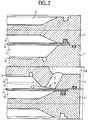
- the elastic membrane filters represented in section in FIG. 2, of which various details of a purely constructive order are not represented, comprise two chambers 12 and 13 separated by a membrane 14. This membrane is clamped in a manner known per se between the elements 4 constituting the frame of the filter.
- the membranes 14 have been shown in FIG. 2 in the rest state in solid lines.
- the filter elements 16 are shown in broken lines.
- the membranes 14 are moved in the direction of the filter elements 16 under the effect of the air pressure exerted in each of the chambers 12.
- the air inlet ducts used for this purpose are not shown in FIG. 2 .
- this angle ⁇ is between approximately 10 ° and approximately 30 ° so that as soon as the membrane 14 comes to occupy the position 14 'shown in dashed points in FIG. 2, the orifice 19 is rigorously closed and the increase in the air pressure in the chamber 12 will gradually increase the perfect obturation of this orifice.
- the inlet duct 17 and its orifice 19 will preferably be placed near the place where the edge of the membrane 14 is retained between the constituent elements of the filter frame.
Abstract
Description
La présente invention concerne un nouveau filtre-presse à membrane élastique. Elle concerne également un procédé de filtration utilisant ledit filtre-presse.The present invention relates to a new elastic membrane filter press. It also relates to a filtration process using said filter press.
La présente invention se rapporte en particulier à un filtre-presse à membrane élastique, notamment pour la filtration de maisches, constitué d'éléments filtrants comportant chacun un cadre et un plateau formant une chambre, chaque élément filtrant étant traversé par un conduit d'alimentation inférieur dont les orifices permettent le passage du liquide à filtrer vers lesdites chambres.The present invention relates in particular to a filter press with an elastic membrane, in particular for filtering housings, consisting of filter elements each comprising a frame and a plate forming a chamber, each filter element being traversed by a supply duct. lower whose orifices allow the passage of the liquid to be filtered towards said chambers.
Les filtres-presses sont bien connus et utilisés largement. Généralement, leur membrane sépare deux chambres dont l'une reçoit le liquide à filtrer lui-même chargé de matières solides, tandis que l'autre délimite un espace dans lequel de l'air peut être introduit. En exerçant une pression sur l'air, la membrane se déplace en direction de l'élément filtrant, provoquant ainsi la compression de la matière solide contenue dans le liquide à filtrer sous forme d'un "gâteau".Filter presses are well known and widely used. Generally, their membrane separates two chambers, one of which receives the liquid to be filtered, itself loaded with solid matter, while the other delimits a space into which air can be introduced. By exerting a pressure on the air, the membrane moves in the direction of the filter element, thus causing the compression of the solid matter contained in the liquid to be filtered in the form of a "cake".
Ces filtres-presses présentent cependant divers inconvénients. Par exemple, à partir du moment où la membrane débute son mouvement en direction de l'élément filtrant, l'arrivée de liquide à filtrer n'est pas interrompue rapidement, ce qui peut provoquer un retour dans le conduit d'alimentation d'une quantité de liquide à filtrer. Il peut s'en suivre un certain encrassement de l'orifice du conduit d'alimentation. Ces phénomènes sont d'autant plus marqués lorsque la fermeture de l'orifice d'entrée est très tardive, ce qui se produit lorsque le conduit d'entrée s'étend tangentiellement ou pratiquement tangentiellement à la membrane.These filter presses, however, have various drawbacks. For example, from the moment the membrane begins its movement towards the filter element, the arrival of liquid to be filtered is not interrupted quickly, which can cause a return in the supply duct of a amount of liquid to be filtered. This may result in some fouling of the orifice of the supply duct. These phenomena are all the more marked when the closing of the inlet orifice is very late, which occurs when the inlet duct extends tangentially or practically tangentially to the membrane.
L'invention a pour but principal d'optimiser la capacité de filtration de tous les éléments constituant le filtre-presse et cela indépendamment de l'éloignement des éléments filtrants par rapport à l'endroit où les produits à filtrer pénètrent dans le conduit d'alimentation inférieure.The main object of the invention is to optimize the filtration capacity of all the elements constituting the filter press, regardless of the distance of the filter elements from the place where the products to be filtered enter the duct. lower feed.
L'invention a également pour but de remédier en grande partie aux inconvénients ci-dessus, notamment ceux liés à l'encrassement de l'orifice du conduit d'alimentation.The object of the invention is also to largely remedy the above drawbacks, in particular those linked to fouling of the orifice of the supply duct.
Le filtre-presse à membrane élastique de l'invention, en particulier pour la filtration de maisches, constitué d'éléments filtrants comportant chacun un cadre et un plateau formant une chambre, chaque élément filtrant étant traversé par un conduit d'alimentation inférieur dont les orifices permettent le passage du liquide à filtrer vers lesdites chambres, est caractérisé en ce qu'il comporte un second conduit d'alimentation, dit conduit d'alimentation supérieur, traversant les chambres de filtration en un endroit situé à l'opposé dudit conduit d'alimentation inférieur, ledit conduit d'alimentation supérieur étant relié au conduit d'alimentation inférieur de manière à être alimenté en liquide à filtrer en aval du conduit d'alimentation inférieur et à contre-courant du conduit d'alimentation inférieur, un conduit reliant entre eux lesdits conduits d'alimentation inférieur et supérieur.The elastic membrane filter press of the invention, in particular for filtering moths, consisting of filter elements each comprising a frame and a plate forming a chamber, each filter element being traversed by a lower supply duct whose orifices allow the passage of the liquid to be filtered towards said chambers, is characterized in that it comprises a second supply duct, said upper supply duct, passing through the filtration chambers at a location situated opposite said duct lower feed, said upper feed duct being connected to the lower feed duct so as to be supplied with liquid to be filtered downstream of the lower feed duct and against the current of the lower feed duct, a duct connecting between them said lower and upper supply conduits.
Selon une forme de réalisation préférée, le filtre à membrane élastique de l'invention permet la coupure de l'alimentation de la chambre qui reçoit le liquide à filtrer pratiquement dès que la pression de l'air augmente dans la chambre située de l'autre côté de la membrane.According to a preferred embodiment, the elastic membrane filter of the invention makes it possible to cut off the supply to the chamber which receives the liquid to be filtered practically as soon as the air pressure increases in the chamber situated on the other side of the membrane.
Selon cette forme de réalisation préférée de l'invention, un orifice d'entrée de la maische traversant l'un des plateaux, en l'occurence le plateau appartenant au compartiment de filtration, débouche dans celui-ci de telle sorte que le plan passant par l'orifice de ce conduit d'entrée forme avec la membrane élastique un angle de 30° au maximum.According to this preferred embodiment of the invention, an inlet opening of the mash passing through one of the plates, in this case the plate belonging to the filtration compartment, opens into the latter so that the plane passing through the orifice of this inlet duct forms an angle of maximum 30 ° with the elastic membrane.
Selon l'invention, le conduit d'entrée présente un axe géométrique qui forme avec la membrane élastique, à l'état de repos, un angle de 60° au maximum.According to the invention, the inlet duct has a geometric axis which forms with the elastic membrane, in the rest state, an angle of 60 ° at most.
Selon une forme de réalisation particulièrement avantageuse de l'invention, le conduit d'entrée ci-dessus débouche face à la membrane élastique en un endroit le plus proche possible du cadre dans lequel le rebord de la membrane élastique est retenu.According to a particularly advantageous embodiment of the invention, the above inlet duct opens facing the elastic membrane in a location as close as possible to the frame in which the edge of the elastic membrane is retained.
L'invention concerne également un procédé de filtration de maisches dans lequel on fait usage du filtre-presse de l'invention. Le procédé a pour but d'optimiser les conditions dans lesquelles travaille le filtre selon l'invention.The invention also relates to a method of filtering out of caches in which use is made of the filter press of the invention. The purpose of the method is to optimize the conditions under which the filter according to the invention works.
Le procédé de l'invention comporte les étapes d'introduction en premier lieu du liquide à filtrer par le conduit d'alimentation inférieur jusqu'au remplissage de toutes les chambres de filtration, éventuellement d'ouverture d'une vanne séparant les conduits d'alimentation inférieur et supérieur lorsque toutes les chambres de filtration sont remplies à partir du conduit d'alimentation inférieur et de poursuite de la filtration en alimentant également les chambres de filtration à partir dudit conduit d'alimentation supérieur.The method of the invention comprises the steps of first introducing the liquid to be filtered through the lower supply duct until all the filtration chambers are filled, possibly with the opening of a valve separating the ducts from lower and upper supply when all the filtration chambers are filled from the lower supply duct and further filtration by also supplying the filtration chambers from said upper supply duct.
Par effet de contre-pression statique dans le conduit de liaison entre les conduits d'alimentation supérieur et inférieur lors du remplissage du filtre, le placement et l'utilisation de la vanne séparant les conduits inférieur et supérieur sont facultatifs.By static back-pressure effect in the connection duct between the upper and lower supply ducts when filling the filter, the placement and use of the valve separating the lower and upper ducts is optional.
D'autres caractéristiques et avantages de l'invention ressortiront encore de la description plus détaillée qui suit d'un filtre-presse à membrane élastique et d'un procédé de filtration de maisches selon l'invention. Il va de soi que cette description n'est donnée qu'à titre purement illustratif et ne constitue en aucune façon une limitation de la présente invention. Les références numériques qui suivent se rapportent aux figures ci-après dans lesquelles :
- la figure 1 représente une vue latérale schématique d'un mode de réalisation du filtre-presse selon l'invention;
- la figure 2 représente une coupe transversale de deux filtres à membrane selon l'invention.
- Figure 1 shows a schematic side view of an embodiment of the filter press according to the invention;
- 2 shows a cross section of two membrane filters according to the invention.
Ainsi qu'il apparaît sur la figure 1, le filtre-presse de l'invention comporte, d'une façon classique, un bâti dont font partie une extrémité fixe 1 et une extrémité mobile 2. Le caisson arrière 3 et l'un des deux éléments longitudinaux 4 le long desquels peuvent être déplacés les éléments filtrants 5 sont représentés sur cette figure 1.As it appears in FIG. 1, the filter press of the invention comprises, in a conventional manner, a frame of which a fixed end 1 and a
Pour la bonne compréhension de l'invention, il a été estimé suffisant de limiter la représentation schématique du filtre-presse aux éléments apparaissant sur la figure 1. C'est ainsi que les moyens avec lesquels les éléments filtrants sont déplacés le long des éléments longitudinaux 4 ne sont pas représentés.For a good understanding of the invention, it was considered sufficient to limit the schematic representation of the filter press to the elements appearing in FIG. 1. This is how the means with which the filter elements are moved along the
Jusqu'alors, l'alimentation des chambres, limitées dans chacun des éléments filtrants à l'espace situé entre la toile de filtration et la membrane souple destinée à comprimer le gâteau est rendue possible par un conduit d'alimentation inférieur représenté par la référence 6. L'alimentation des éléments filtrants se réalise à partir de l'extrémité 7 de ce conduit d'alimentation inférieur 6.Until then, the supply of the chambers, limited in each of the filter elements to the space between the filter cloth and the flexible membrane intended to compress the cake, is made possible by a lower supply duct represented by the
Le liquide à filtrer qui pénètre dans le conduit d'alimentation inférieur 6 circule dans le sens indiqué par la flèche 8. On constate dans les filtres de l'art antérieur que rapidement et à mesure que la filtration progresse, la répartition, dans les chambres des éléments filtrants, de la fraction solide du liquide à filtrer se présente de façon irrégulière de chambre à chambre.The liquid to be filtered which enters the
Le filtre de l'invention remédie de façon remarquable à cette répartition irrégulière de la fraction solide du remplissage et conduit à une optimisation des éléments filtrants.The filter of the invention remarkably remedies this irregular distribution of the solid fraction of the filling and leads to an optimization of the filter elements.
Ceci est en effet obtenu en prolongeant le conduit d'alimentation inférieur 6 par un conduit d'alimentation supérieur 9 relié à ce dernier par une section de conduit vertical 10 ou sensiblement vertical sur laquelle est avantageusement branchée une vanne 11.This is in fact obtained by extending the
Le conduit d'alimentation supérieur 9 remplit donc une fonction identique à celle que remplit le conduit inférieur 6. Le processus de filtration se poursuit en alimentant les chambres par les conduits supérieur et inférieur, soit par ouverture de la vanne 11, soit par effet de vase communicant lorsque la vanne 11 n'est pas installée. On constate alors une égalisation du remplissage des différentes chambres tant au point de vue quantitatif qu'au point de vue de la répartition granulométrique, en raison de l'alimentation double à contre-courant à partir des conduits d'alimentation inférieur et supérieur. Les performances du filtre en sont notablement améliorées.The
Ainsi qu'il apparaît sur la figure 2, les filtres à membrane élastique représentés en coupe sur la figure 2, dont divers détails d'ordre purement constructif ne sont pas représentés, comportent deux chambres 12 et 13 séparées par une membrane 14. Cette membrane est serrée de manière connue en soi entre les éléments 4 constituant le cadre du filtre.As it appears in FIG. 2, the elastic membrane filters represented in section in FIG. 2, of which various details of a purely constructive order are not represented, comprise two
Les membranes 14 ont été représentées sur la figure 2 à l'état de repos en traits pleins. Les éléments filtrants 16 sont représentés en traits interrompus.The
Les membranes 14 sont déplacées en direction des éléments filtrants 16 sous l'effet de la pression de l'air exercée dans chacune des chambres 12. Les conduits d'entrée de l'air utilisés à cet effet ne sont pas représentés sur la figure 2.The
On a cependant représenté en points-tirets la position qu'occupe l'une des membranes, en l'occurence la membrane 14', lorsque celle-ci est déplacée sous l'effet de la pression de l'air, en direction de l'élément filtrant 16 dans le but de comprimer le gâteau.However, there has been shown in dashed points the position occupied by one of the membranes, in this case the
Il est apparu qu'un bon fonctionnement du filtre est entravé lorsque, la membrane étant déplacée sous la pression de l'air dans la chambre 13, I'arrivée du liquide à filtrer par le conduit d'entrée 17 qui prolonge le conduit d'alimentation 18 n'est pas arrêtée rapidement. On observe alors en effet un reflux par le conduit d'entrée 17 et le conduit d'alimentation 18 du liquide à filtrer.It appeared that proper functioning of the filter is hampered when, the membrane being moved under the pressure of air in the
Dans ces circonstances, un encrassement de cet orifice d'entrée se produit régulièrement et cette situation n'est pas désirée.Under these circumstances, fouling of this inlet orifice occurs regularly and this situation is not desired.
Selon l'invention, il est maintenant possible d'arrêter l'entrée du liquide à filtrer dans l'instant qui suit le début du déplacement de la membrane 14 sous l'influence de l'air injecté dans chacune des chambres 12. Ce résultat est atteint en disposant le conduit d'entrée 17 et principalement son orifice d'entrée 19 dans un plan tel, par rapport à une membrane 14 au repos, que le conduit d'entrée 17 soit obturé par la membrane 14 dès que son déplacement est provoqué par l'augmentation du volume variable de la chambre 12 sous l'influence de l'air injecté dans cette chambre.According to the invention, it is now possible to stop the entry of the liquid to be filtered in the instant following the start of movement of the
Ceci est atteint grâce à l'angle α défini entre le plan passant par l'orifice d'entrée 19 et la membrane 14 à l'état de repos.This is achieved by the angle α defined between the plane passing through the
Avantageusement, cet angle α se situe entre environ 10° et environ 30° de telle sorte que dès que la membrane 14 vient occuper la position 14' représentée en points-tirets sur la figure 2, l'orifice 19 est rigoureusement obturé et l'augmentation de la pression d'air dans la chambre 12 augmentera progressivement l'obturation parfaite de cet orifice.Advantageously, this angle α is between approximately 10 ° and approximately 30 ° so that as soon as the
En pratique, l'angle défini entre l'axe géométrique de l'orifice d'entrée 17 et la membrane 14 à l'état de repos n'est pas déterminant à lui seul.In practice, the angle defined between the geometric axis of the
Dans un filtre à membrane du type considéré, on disposera de préférence le conduit d'entrée 17 et son orifice 19 à proximité de l'endroit où le rebord de la membrane 14 est retenu entre les éléments constitutifs du cadre du filtre.In a membrane filter of the type under consideration, the
De la description qui vient d'être donnée du filtre à membrane élastique selon l'invention, on comprendra que l'obturation pratiquement instantanée de l'orifice d'entrée se produit dès que la membrane entame son mouvement en direction de l'élément filtrant sous l'influence de l'augmentation du volume d'air et de sa pression dans chacune des chambres 12.From the description which has just been given of the elastic membrane filter according to the invention, it will be understood that the practically instantaneous obturation of the inlet orifice occurs as soon as the membrane begins its movement towards the filter element. under the influence of the increase in the volume of air and its pressure in each of the
Il va de soi que l'invention n'est pas limitée à la forme d'éxécution préférée qui vient d'être décrite et que des modifications peuvent y être apportées sans pour autant sortir des caractéristiques essentielles de l'invention, l'étendue de la protection étant déterminée par les revendications qui suivent.It goes without saying that the invention is not limited to the preferred embodiment which has just been described and that modifications can be made thereto without departing from the essential characteristics of the invention, the scope of protection being determined by the claims which follow.
Claims (5)
Applications Claiming Priority (2)
| Application Number | Priority Date | Filing Date | Title |
|---|---|---|---|
| FR9403885A FR2718053B1 (en) | 1994-04-01 | 1994-04-01 | Elastic membrane filter press, filtration process using such a filter. |
| FR9403885 | 1994-04-01 |
Publications (2)
| Publication Number | Publication Date |
|---|---|
| EP0674929A1 true EP0674929A1 (en) | 1995-10-04 |
| EP0674929B1 EP0674929B1 (en) | 1999-11-03 |
Family
ID=9461679
Family Applications (1)
| Application Number | Title | Priority Date | Filing Date |
|---|---|---|---|
| EP95400625A Expired - Lifetime EP0674929B1 (en) | 1994-04-01 | 1995-03-21 | Filter press provided with elastic diaphragm and filtration process using such a filter |
Country Status (7)
| Country | Link |
|---|---|
| US (1) | US5658468A (en) |
| EP (1) | EP0674929B1 (en) |
| JP (1) | JP2815552B2 (en) |
| AT (1) | ATE186225T1 (en) |
| DE (1) | DE69513069T2 (en) |
| ES (1) | ES2140632T3 (en) |
| FR (1) | FR2718053B1 (en) |
Cited By (5)
| Publication number | Priority date | Publication date | Assignee | Title |
|---|---|---|---|---|
| EP0786280A2 (en) * | 1996-01-27 | 1997-07-30 | Lenser Kunststoff-Presswerk GmbH & Co. KG | Membrane filter plate for a filter press |
| CN102580372A (en) * | 2012-01-12 | 2012-07-18 | 杭州兴源过滤科技股份有限公司 | Coal slime filter-press test system and coal slime test method |
| EP3138620A1 (en) | 2015-08-21 | 2017-03-08 | Meura S.A. | Filtration method in a membrane filter press |
| CN109011748A (en) * | 2018-09-07 | 2018-12-18 | 安徽金贺财建筑工程有限公司 | A kind of efficient membrane filter plate filter press |
| EP3617301A1 (en) | 2018-08-29 | 2020-03-04 | Heineken Supply Chain B.V. | Mash filter membrane |
Families Citing this family (7)
| Publication number | Priority date | Publication date | Assignee | Title |
|---|---|---|---|---|
| DE10221061B4 (en) * | 2002-05-10 | 2006-03-09 | Jvk Filtration Systems Gmbh | Membrane, membrane plate and plate pack for a filter press |
| DE10219563B4 (en) * | 2002-05-01 | 2006-06-14 | Filippo Pizzo | Membrane chamber filter press |
| AT504343B8 (en) * | 2006-09-01 | 2008-09-15 | Andritz Tech & Asset Man Gmbh | CUTTING ELEMENT FOR A FILTER PRESS |
| DK2838637T3 (en) | 2012-04-19 | 2019-07-01 | Outotec Finland Oy | FILTER DEVICE AND PROCEDURE FOR FILTERING A SUSPENSION |
| CN109381902A (en) * | 2018-11-15 | 2019-02-26 | 程晓洁 | A kind of diaphragm mash filter |
| CN109499120A (en) * | 2018-12-28 | 2019-03-22 | 启明星宇节能科技股份有限公司 | A kind of feeding of filter press pipe connection |
| DE102021133455A1 (en) | 2021-12-16 | 2023-06-22 | Steinecker GmbH | Mash filter and method of filtering mash |
Citations (4)
| Publication number | Priority date | Publication date | Assignee | Title |
|---|---|---|---|---|
| DE132201C (en) * | ||||
| GB858634A (en) * | 1956-12-20 | 1961-01-11 | Licencia Talalmanyokat | Improvements in or relating to chamber filter presses |
| DE2503674A1 (en) * | 1974-01-30 | 1975-07-31 | Moseley Rubber Co Ltd | METHOD AND DEVICE FOR FILTRATION, IN PARTICULAR OF WASTE WATER |
| WO1992020424A1 (en) * | 1991-05-23 | 1992-11-26 | Eberhard Hoesch & Söhne Gmbh Verfahrens- Und Anlagentechnik | Plate filter |
Family Cites Families (11)
| Publication number | Priority date | Publication date | Assignee | Title |
|---|---|---|---|---|
| US1011130A (en) * | 1909-09-03 | 1911-12-05 | Frederick W Mangelsdorff | Filter. |
| DE1223342B (en) * | 1962-05-17 | 1966-08-25 | Seitz Werke Gmbh | Filter press with a fixed lid supporting the fittings and a movable lid |
| US3669267A (en) * | 1970-07-07 | 1972-06-13 | Shriver & Co Inc T | Filter press plate process and apparatus |
| US4346003A (en) * | 1980-11-03 | 1982-08-24 | Polyakov Nikolai F | Mash-separating filter-press |
| DE3129736C2 (en) * | 1981-07-28 | 1985-11-14 | Passavant-Werke AG & Co KG, 6209 Aarbergen | Method for applying a layer of filter aid or precoat to filter cloths of a plate filter press, as well as plate filter press for carrying out the method |
| DE3128970A1 (en) * | 1981-07-22 | 1983-03-03 | Rittershaus & Blecher Gmbh, 5600 Wuppertal | "DIAPHRAGM FILTER PLATE FOR FILTER PRESSES" |
| FR2585264B1 (en) * | 1985-06-04 | 1990-03-23 | Parmentier Alfred H | PRESS FILTERS |
| US4781828A (en) * | 1985-12-23 | 1988-11-01 | Bauko Baukooperation Gmbh | Filter press with rotor disks |
| JPH0753203B2 (en) * | 1987-08-03 | 1995-06-07 | 功 松下 | Press filtration method |
| FI79031C (en) * | 1988-08-03 | 1989-11-10 | Larox Ag | FILTRERINGSFOERFARANDE. |
| DE3932422C2 (en) * | 1989-09-28 | 1995-04-13 | Krupp Maschinentechnik | Plate filter press |
-
1994
- 1994-04-01 FR FR9403885A patent/FR2718053B1/en not_active Expired - Lifetime
-
1995
- 1995-03-21 DE DE69513069T patent/DE69513069T2/en not_active Expired - Lifetime
- 1995-03-21 EP EP95400625A patent/EP0674929B1/en not_active Expired - Lifetime
- 1995-03-21 AT AT95400625T patent/ATE186225T1/en active
- 1995-03-21 ES ES95400625T patent/ES2140632T3/en not_active Expired - Lifetime
- 1995-03-23 US US08/408,943 patent/US5658468A/en not_active Expired - Lifetime
- 1995-04-03 JP JP7077478A patent/JP2815552B2/en not_active Expired - Lifetime
Patent Citations (4)
| Publication number | Priority date | Publication date | Assignee | Title |
|---|---|---|---|---|
| DE132201C (en) * | ||||
| GB858634A (en) * | 1956-12-20 | 1961-01-11 | Licencia Talalmanyokat | Improvements in or relating to chamber filter presses |
| DE2503674A1 (en) * | 1974-01-30 | 1975-07-31 | Moseley Rubber Co Ltd | METHOD AND DEVICE FOR FILTRATION, IN PARTICULAR OF WASTE WATER |
| WO1992020424A1 (en) * | 1991-05-23 | 1992-11-26 | Eberhard Hoesch & Söhne Gmbh Verfahrens- Und Anlagentechnik | Plate filter |
Cited By (7)
| Publication number | Priority date | Publication date | Assignee | Title |
|---|---|---|---|---|
| EP0786280A2 (en) * | 1996-01-27 | 1997-07-30 | Lenser Kunststoff-Presswerk GmbH & Co. KG | Membrane filter plate for a filter press |
| EP0786280A3 (en) * | 1996-01-27 | 1997-09-10 | Lenser Kunststoff Press | |
| CN102580372A (en) * | 2012-01-12 | 2012-07-18 | 杭州兴源过滤科技股份有限公司 | Coal slime filter-press test system and coal slime test method |
| EP3138620A1 (en) | 2015-08-21 | 2017-03-08 | Meura S.A. | Filtration method in a membrane filter press |
| EP3617301A1 (en) | 2018-08-29 | 2020-03-04 | Heineken Supply Chain B.V. | Mash filter membrane |
| WO2020046122A1 (en) | 2018-08-29 | 2020-03-05 | Heineken Supply Chain B.V. | Mash filter membrane |
| CN109011748A (en) * | 2018-09-07 | 2018-12-18 | 安徽金贺财建筑工程有限公司 | A kind of efficient membrane filter plate filter press |
Also Published As
| Publication number | Publication date |
|---|---|
| FR2718053A1 (en) | 1995-10-06 |
| US5658468A (en) | 1997-08-19 |
| ES2140632T3 (en) | 2000-03-01 |
| FR2718053B1 (en) | 1996-05-31 |
| JP2815552B2 (en) | 1998-10-27 |
| DE69513069D1 (en) | 1999-12-09 |
| ATE186225T1 (en) | 1999-11-15 |
| DE69513069T2 (en) | 2000-07-20 |
| EP0674929B1 (en) | 1999-11-03 |
| JPH08238404A (en) | 1996-09-17 |
Similar Documents
| Publication | Publication Date | Title |
|---|---|---|
| EP0674929A1 (en) | Filter press provided with elastic diaphragm and filtration process using such a filter | |
| EP0975411B1 (en) | Filter and filter cartridge with peripheral stop for filtering liquids circulating in an engine or in a hydraulic equipment | |
| FR2674448A1 (en) | Process for cleaning mesoporous tubular ultrafiltration membranes | |
| EP0547951B1 (en) | Gasoil filter | |
| EP0251840A1 (en) | Process and individual apparatus for the filtration of a liquid | |
| EP1535057A1 (en) | Device for separating sample components by liquid chromatography under pressure | |
| FR2851790A1 (en) | Fuel filter comprises casing with inlet and outlet on non-filtered and filtered sides respectively, filter element between two sides and water separation and evacuation chambers on both sides with outlet orifice closed by joint | |
| WO1988010239A1 (en) | Process and apparatus for producing drinking water | |
| FR2550710A1 (en) | Plant for filtering water laden with mineral and/or vegetable particles | |
| FR2663240A1 (en) | Apparatus for the separation of a liquid and of the solid particles in suspension which it contains | |
| FR2679465A1 (en) | METHOD AND DEVICE FOR DECOLMAGING FILTRATION MEMBRANES | |
| EP1175995B1 (en) | Press for material from grape harvesting | |
| FR2589508A1 (en) | SELF-PROPELLING SWIMMING POOL CLEANING DEVICE | |
| EP0975406A1 (en) | Separator for three-phase mixture to be used under the sea | |
| EP0423043A1 (en) | Filtering device for swimmingpools | |
| FR2804881A1 (en) | Filter to clean water at a swimming pool has a sealed chamber with a pliable shrouding wall containing an inner filter sleeve with an absorbent filter material where the filter cake is broken up during the filtering action | |
| EP1349643B1 (en) | Backwashing of a hollow fibre filter operating in dead-end mode | |
| WO1993004760A1 (en) | Method and device for the filtration of a liquid containing suspension particles | |
| FR2618727A1 (en) | Ink jet printers comprising a suction manifold and a manifold connected to a reservoir for storing compressed gases and vapours | |
| FR2746666A1 (en) | Apparatus for removing dust from air | |
| EP0444976A1 (en) | Pressing apparatus | |
| FR2780981A1 (en) | METHOD OF ONLINE FILTRATION OF A LIQUID METAL AND DEVICE FOR CARRYING OUT SAID METHOD | |
| FR2576521A1 (en) | Device for filtering the water of a swimming pool | |
| FR2553297A1 (en) | LIQUID FILTER, IN PARTICULAR FOR CONTINUOUS REMOVAL OF PARTICLES CONTAINED IN WATER AFTER CUTTING OF SEMICONDUCTOR DEVICES | |
| EP0452191A1 (en) | Deduster with rigid filter element and purification by countercurrant blowing with a nozzle |
Legal Events
| Date | Code | Title | Description |
|---|---|---|---|
| PUAI | Public reference made under article 153(3) epc to a published international application that has entered the european phase |
Free format text: ORIGINAL CODE: 0009012 |
|
| AK | Designated contracting states |
Kind code of ref document: A1 Designated state(s): AT BE CH DE ES GB IT LI LU NL SE |
|
| 17P | Request for examination filed |
Effective date: 19951019 |
|
| 17Q | First examination report despatched |
Effective date: 19970916 |
|
| GRAG | Despatch of communication of intention to grant |
Free format text: ORIGINAL CODE: EPIDOS AGRA |
|
| GRAG | Despatch of communication of intention to grant |
Free format text: ORIGINAL CODE: EPIDOS AGRA |
|
| GRAH | Despatch of communication of intention to grant a patent |
Free format text: ORIGINAL CODE: EPIDOS IGRA |
|
| RAP1 | Party data changed (applicant data changed or rights of an application transferred) |
Owner name: KRONTEC S.A. Owner name: MEURA S.A. Owner name: INTERBREW SOCIETE ANONYME |
|
| GRAH | Despatch of communication of intention to grant a patent |
Free format text: ORIGINAL CODE: EPIDOS IGRA |
|
| RAP1 | Party data changed (applicant data changed or rights of an application transferred) |
Owner name: KRONTEC S.A. Owner name: MEURA S.A. Owner name: INTERBREW |
|
| GRAA | (expected) grant |
Free format text: ORIGINAL CODE: 0009210 |
|
| AK | Designated contracting states |
Kind code of ref document: B1 Designated state(s): AT BE CH DE ES GB IT LI LU NL SE |
|
| REF | Corresponds to: |
Ref document number: 186225 Country of ref document: AT Date of ref document: 19991115 Kind code of ref document: T |
|
| REG | Reference to a national code |
Ref country code: CH Ref legal event code: NV Representative=s name: NOVAPAT INTERNATIONAL S.A. Ref country code: CH Ref legal event code: EP |
|
| REF | Corresponds to: |
Ref document number: 69513069 Country of ref document: DE Date of ref document: 19991209 |
|
| ITF | It: translation for a ep patent filed |
Owner name: JACOBACCI & PERANI S.P.A. |
|
| GBT | Gb: translation of ep patent filed (gb section 77(6)(a)/1977) |
Effective date: 19991123 |
|
| REG | Reference to a national code |
Ref country code: ES Ref legal event code: FG2A Ref document number: 2140632 Country of ref document: ES Kind code of ref document: T3 |
|
| PLBE | No opposition filed within time limit |
Free format text: ORIGINAL CODE: 0009261 |
|
| STAA | Information on the status of an ep patent application or granted ep patent |
Free format text: STATUS: NO OPPOSITION FILED WITHIN TIME LIMIT |
|
| 26N | No opposition filed | ||
| REG | Reference to a national code |
Ref country code: GB Ref legal event code: IF02 |
|
| BECA | Be: change of holder's address |
Owner name: CHAUSS?E D'ANTOING 55, B-7500 TOURNAI (BE) Effective date: 20050913 Owner name: 48, RUE LOUIS XIV, L-1948 LUXEMBOURG (LU) Effective date: 20050913 Owner name: *BEREWTECGRAND' PLACE 1, B-1000 BRUXELLES Effective date: 20050913 Owner name: S.A. *MEURA Effective date: 20050913 Owner name: *INTERBREW Effective date: 20050913 |
|
| PGFP | Annual fee paid to national office [announced via postgrant information from national office to epo] |
Ref country code: LU Payment date: 20140326 Year of fee payment: 20 Ref country code: DE Payment date: 20140328 Year of fee payment: 20 Ref country code: CH Payment date: 20140319 Year of fee payment: 20 Ref country code: SE Payment date: 20140319 Year of fee payment: 20 Ref country code: NL Payment date: 20140319 Year of fee payment: 20 |
|
| PGFP | Annual fee paid to national office [announced via postgrant information from national office to epo] |
Ref country code: AT Payment date: 20140312 Year of fee payment: 20 Ref country code: IT Payment date: 20140326 Year of fee payment: 20 |
|
| PGFP | Annual fee paid to national office [announced via postgrant information from national office to epo] |
Ref country code: GB Payment date: 20140319 Year of fee payment: 20 |
|
| PGFP | Annual fee paid to national office [announced via postgrant information from national office to epo] |
Ref country code: BE Payment date: 20140319 Year of fee payment: 20 |
|
| REG | Reference to a national code |
Ref country code: DE Ref legal event code: R071 Ref document number: 69513069 Country of ref document: DE |
|
| REG | Reference to a national code |
Ref country code: DE Ref legal event code: R071 Ref document number: 69513069 Country of ref document: DE |
|
| REG | Reference to a national code |
Ref country code: CH Ref legal event code: PL |
|
| REG | Reference to a national code |
Ref country code: NL Ref legal event code: V4 Effective date: 20150321 |
|
| REG | Reference to a national code |
Ref country code: GB Ref legal event code: PE20 Expiry date: 20150320 |
|
| REG | Reference to a national code |
Ref country code: SE Ref legal event code: EUG |
|
| REG | Reference to a national code |
Ref country code: AT Ref legal event code: MK07 Ref document number: 186225 Country of ref document: AT Kind code of ref document: T Effective date: 20150321 |
|
| REG | Reference to a national code |
Ref country code: ES Ref legal event code: FD2A Effective date: 20150528 |
|
| PG25 | Lapsed in a contracting state [announced via postgrant information from national office to epo] |
Ref country code: GB Free format text: LAPSE BECAUSE OF EXPIRATION OF PROTECTION Effective date: 20150320 |
|
| PG25 | Lapsed in a contracting state [announced via postgrant information from national office to epo] |
Ref country code: ES Free format text: LAPSE BECAUSE OF EXPIRATION OF PROTECTION Effective date: 20150322 |
|
| PGFP | Annual fee paid to national office [announced via postgrant information from national office to epo] |
Ref country code: ES Payment date: 20140331 Year of fee payment: 20 |