EP0674889A1 - Knee-brace - Google Patents
Knee-brace Download PDFInfo
- Publication number
- EP0674889A1 EP0674889A1 EP95103917A EP95103917A EP0674889A1 EP 0674889 A1 EP0674889 A1 EP 0674889A1 EP 95103917 A EP95103917 A EP 95103917A EP 95103917 A EP95103917 A EP 95103917A EP 0674889 A1 EP0674889 A1 EP 0674889A1
- Authority
- EP
- European Patent Office
- Prior art keywords
- knee
- knee brace
- cushion
- brace according
- sleeve
- Prior art date
- Legal status (The legal status is an assumption and is not a legal conclusion. Google has not performed a legal analysis and makes no representation as to the accuracy of the status listed.)
- Granted
Links
Images


Classifications
-
- A—HUMAN NECESSITIES
- A61—MEDICAL OR VETERINARY SCIENCE; HYGIENE
- A61F—FILTERS IMPLANTABLE INTO BLOOD VESSELS; PROSTHESES; DEVICES PROVIDING PATENCY TO, OR PREVENTING COLLAPSING OF, TUBULAR STRUCTURES OF THE BODY, e.g. STENTS; ORTHOPAEDIC, NURSING OR CONTRACEPTIVE DEVICES; FOMENTATION; TREATMENT OR PROTECTION OF EYES OR EARS; BANDAGES, DRESSINGS OR ABSORBENT PADS; FIRST-AID KITS
- A61F5/00—Orthopaedic methods or devices for non-surgical treatment of bones or joints; Nursing devices; Anti-rape devices
- A61F5/01—Orthopaedic devices, e.g. splints, casts or braces
- A61F5/04—Devices for stretching or reducing fractured limbs; Devices for distractions; Splints
- A61F5/05—Devices for stretching or reducing fractured limbs; Devices for distractions; Splints for immobilising
- A61F5/058—Splints
- A61F5/05841—Splints for the limbs
- A61F5/0585—Splints for the limbs for the legs
-
- A—HUMAN NECESSITIES
- A61—MEDICAL OR VETERINARY SCIENCE; HYGIENE
- A61F—FILTERS IMPLANTABLE INTO BLOOD VESSELS; PROSTHESES; DEVICES PROVIDING PATENCY TO, OR PREVENTING COLLAPSING OF, TUBULAR STRUCTURES OF THE BODY, e.g. STENTS; ORTHOPAEDIC, NURSING OR CONTRACEPTIVE DEVICES; FOMENTATION; TREATMENT OR PROTECTION OF EYES OR EARS; BANDAGES, DRESSINGS OR ABSORBENT PADS; FIRST-AID KITS
- A61F5/00—Orthopaedic methods or devices for non-surgical treatment of bones or joints; Nursing devices; Anti-rape devices
- A61F5/01—Orthopaedic devices, e.g. splints, casts or braces
- A61F5/0102—Orthopaedic devices, e.g. splints, casts or braces specially adapted for correcting deformities of the limbs or for supporting them; Ortheses, e.g. with articulations
- A61F5/0104—Orthopaedic devices, e.g. splints, casts or braces specially adapted for correcting deformities of the limbs or for supporting them; Ortheses, e.g. with articulations without articulation
- A61F5/0106—Orthopaedic devices, e.g. splints, casts or braces specially adapted for correcting deformities of the limbs or for supporting them; Ortheses, e.g. with articulations without articulation for the knees
- A61F5/0109—Sleeve-like structures
-
- A—HUMAN NECESSITIES
- A61—MEDICAL OR VETERINARY SCIENCE; HYGIENE
- A61F—FILTERS IMPLANTABLE INTO BLOOD VESSELS; PROSTHESES; DEVICES PROVIDING PATENCY TO, OR PREVENTING COLLAPSING OF, TUBULAR STRUCTURES OF THE BODY, e.g. STENTS; ORTHOPAEDIC, NURSING OR CONTRACEPTIVE DEVICES; FOMENTATION; TREATMENT OR PROTECTION OF EYES OR EARS; BANDAGES, DRESSINGS OR ABSORBENT PADS; FIRST-AID KITS
- A61F5/00—Orthopaedic methods or devices for non-surgical treatment of bones or joints; Nursing devices; Anti-rape devices
- A61F5/01—Orthopaedic devices, e.g. splints, casts or braces
- A61F5/0102—Orthopaedic devices, e.g. splints, casts or braces specially adapted for correcting deformities of the limbs or for supporting them; Ortheses, e.g. with articulations
- A61F5/0123—Orthopaedic devices, e.g. splints, casts or braces specially adapted for correcting deformities of the limbs or for supporting them; Ortheses, e.g. with articulations for the knees
- A61F5/0125—Orthopaedic devices, e.g. splints, casts or braces specially adapted for correcting deformities of the limbs or for supporting them; Ortheses, e.g. with articulations for the knees the device articulating around a single pivot-point
Definitions
- the invention relates to a knee brace with a sleeve to be placed on the leg and held together on the front of the leg.
- Surgical interventions on the knee require postoperative immobilization, which is traditionally produced by a functional plaster cast.
- Plastic plasters or splints that are angled with elastic bandages are typically found here. In mobile patients, these bandages are often replaced by Velcro strips that are attached directly to bowl-shaped rails. These shells are often padded to increase comfort.
- a knee brace with a flexible jacket is known, the side edges of which are held together after the jacket has been put on the leg on the front of the leg and each have a recess for the patella, adjustable locking elements along these side edges are provided and the jacket is provided with stiffening bars on the areas that come to rest on the side surfaces and the back of the leg after the jacket has been put on.
- the sheath of this knee brace is composed of several anatomically correct blanks, the blanks and the reinforcing rods have to fix the knee joint in a flexion of about 20 o particular shape and curvature.
- the knee brace according to DE-A-42 29 044 also consists of a flexible jacket which is provided on its side edges with closure elements which hold the jacket together in the form of a closed tube after it has been placed on the leg, wherein the longitudinal axis of the part surrounding the lower leg assumes an angular position to the longitudinal axis of the part surrounding the thigh.
- the blank forming the sheath is formed in one piece and can be unwound in one plane, wherein in the unwound state a recess is provided which extends essentially parallel to the longitudinal axis of the leg and which has larger dimensions along the device than transversely thereto.
- the recess does not reach the closest edge of the blank on at least one of its ends.
- the two longitudinal side edges of the recess are connected to one another when the knee brace is finished.
- the knee braces consist of a flexible jacket. If this coat is composed of several blanks, great precision is always required when sewing. An inaccurate abutting and joining of the individual blanks can lead to an incorrect shape and thus to a poor fit of the rail.
- Both known knee braces are formed so that they fix o the knee in a predetermined bent position of approximately 20, with a course of treatment occurring in the loosening of the knee brace is correctable. In order to meet this predetermined flexed position, the shells of the knee braces of several anatomically correct blanks are put together, the blanks and the reinforcing rods have to fix the knee joint in a flexion of about 20 o particular shape and curvature.
- knee braces Due to the given shells that form the knee braces, there are often fitting problems and difficulties in adapting. Ultimately, these well-known knee braces must be custom-made. In addition, that also when the knee is not in use, the patient cannot do any stretching exercises with the known knee braces. Since the sheaths of these knee braces cover the leg on all sides when put on, heat build-up cannot be avoided.
- a knee orthosis which consists of an elastic flat structure which is placed like a sleeve in the knee area on the upper and lower leg and is held on the leg by means of a plurality of fastening straps.
- the leg is completely enclosed by the knee orthosis when it is in place; only one opening for the patella is left open.
- stiffening bars are provided on the fabric, of which the middle three stiffening bars opposite the patella, i.e. the stiffening bars arranged directly behind the hollow of the knee, are the most important.
- a stiffening rod can be provided on each side.
- the stiffening rods do not lie there on the leg, which can cause the orthosis to slide back and forth on the leg, even if the fastener straps are tightened. For this reason, a soft pad is attached to the inner surface of the knee orthosis at this point. This cushion only fills the back of the knee; however, it does not keep the knee in the bent position of 10 o to 20 o required for successful treatment, since the pad is relatively flat and is only intended to reduce the slipping of the applied orthosis.
- the object of the present invention is to create a postoperative knee splint for immobilizing the knee joint, expediently in a functional, slightly bent position, which enables the patient to perform stretching exercises in the splint with the knee brace on, which enables individual adaptation to different leg sizes and dimensions as well as leg contours, has a heat-preventing construction and is extremely comfortable to wear.
- the sleeve forming the knee splint according to the invention has a cushion made of a dimensionally stable, compressible and resilient plastic that holds the knee in a predetermined bending position of approximately 10 o to 20 o , expediently from 15 o to 20 o , when the knee splint is applied , expediently on a foam plastic or another suitable material, the cushion also being removable so that the knee brace can also be used when the leg is to be held in an extended position.
- This knee flexion cushion consists of an approximately semicircular shaped body with a width supporting the leg in the area of the hollow of the knee.
- the shape and dimensions of the pillow achieve the desired and required bending.
- the knee flexion cushion is preferably dimensioned such that in its longitudinal cross-sectional area the surface of an isosceles, right-angled triangle with its base resting on the cushion base surface can be placed with a center line corresponding to the radius of the semicircular shaped body.
- the sleeve of the knee brace is used to form a Flexible, but stable half-shell made of two stable, high inherent rigidity side parts, which were attached to each other at their two ends via a length-adjustable fastener tape and in the middle via a connecting bar with the side area on the two side parts, to form a medium fastener tape fastener parts which can be connected to one another are connected, the knee flexion cushion, which runs in the longitudinal direction of the knee brace and which has at least one width corresponding to the knee width, being arranged on the approximately central connecting web.
- the knee flexion cushion is detachably arranged on the inside of the central connecting web of the cup-shaped sleeve and is held in a position-changing manner on the central connecting web, so that an individual adaptation to the knee bending area of the leg and its anatomy is possible.
- the side parts of the sleeve have, as stabilizing elements, at least one tubular rod running in the longitudinal direction of the knee splint, three tubular rods preferably being provided in each side part of the sleeve and lying parallel to one another.
- the individual tubular rods are arranged in pocket-shaped chambers which are formed in each side part of the sleeve, for which purpose each side part consists of a double-walled fabric strip.
- the tubular rods of each side part of the sleeve are preferably designed to run straight with bends in the lower calf area.
- the tubular rods consist of a light metal, expediently of aluminum, glass fiber reinforced plastic or are designed as carbon fiber rods.
- a V-shaped and tapered configuration of the two side parts of the sleeve in the direction of the calf area enables adaptation to the anatomical and biomechanical conditions.
- a shape-sewn knee sleeve is created as a functional knee support rail for stabilizing and immobilizing the knee joint in a functional, slightly bent position.
- the knee brace consists of laterally arranged stabilizing bars which are connected to one another via fastening straps, these fastening straps being closable on the front of the leg by overlapping Velcro fasteners or other trained fasteners such as buckles or the like.
- the squat holding pad is made in the half-shell-shaped sleeve made of dimensionally stable foam, in order to bring the knee in the desired light bent posture of about 10 o to 20 o.
- the foam used is compressible when force and pressure are applied, so that the patient can perform stretching exercises in the positioning rail with the knee brace on. Without exerting force, the leg is put back into a slight bending position.
- the cushion with a cushion-like effect is attached to the inside of the bowl-shaped sleeve with a Velcro strap, ie adjustable in length, so that it can be placed correctly and individually. In the case of an upright patient, the pillow prevents the knee splint from slipping by being supported on the lower leg muscles.
- stabilization of the knee can be achieved by fixation at three points: Two places on the back of the leg, on the thigh and lower leg, one place on the front of the leg, on the tibia just below the patella. Accordingly, the rear fastening straps on the thigh and lower leg as well as the front, central fastening band are strong and firm connected to the side stabilization elements. This firm anchoring is crucial for the functionality of the knee brace.
- the lateral stabilizing elements or the lateral tubular rods do not specify the bending angle of the knee, but are preferably straight with a bend in the lower calf area for better adaptation to the anatomy. These stabilizing bars can be reshaped for individual adjustment of the knee brace.
- the side stabilizing rods of the sleeve are round, arranged several times and thus have a very good stabilizing effect with a light weight and simple construction.
- the knee brace thus consists of a basic construction with two stable side parts, which are connected at the top and bottom by fastener straps. This construction creates a flexible but stable half-shell, in which the leg can be placed. After attaching the fasteners, a sleeve surrounding the leg is created. In order to bend the knee, the knee cushion is attached in this half-shell-like sleeve. The stabilization of the knee is achieved by the front closure band below the patella in connection with this half-shell-like sleeve.
- the knee brace As a postoperative knee brace, it offers a high level of therapeutic safety.
- the knee is immobilizable and defined too stabilize. A lasting, constant stabilizing effect is achieved.
- the knee is immobilized in a defined, slight flexion position that relaxes the anterior cruciate ligament.
- the knee brace fits snugly on the leg and is anchored in a torsionally stable manner. Good soft tissue support is achieved on the lower leg.
- the knee brace can be adjusted to different thigh and lower leg widths.
- This knee brace is very comfortable to wear, because the knee brace does not rub, does not constrict, does not wear much, is very light due to its low weight; it is skin-friendly, permeable to air and water vapor and has no unpleasant heat effect.
- the knee brace is easy to put on. The healing process is easy to control. Postoperative wound care is possible. By using suitable materials, the knee brace is insensitive to dirt.
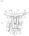
- the knee brace 100 consists of a sleeve 10 to be placed on the leg of a patient and held together on the front of the leg, which on the inside 11 in the area of the hollow of the knee of the leg when the knee brace 100 is applied, the knee in a predetermined bending position of about 10 o to 20 o , expediently from 15 o to 20 o or from 15 o or 20 o, holding cushion 30.
- This knee flexion or cushion pad 30 consists of a dimensionally stable, compressible and resilient plastic, expediently made of a foam plastic. Open or closed-cell foam plastics with a corresponding resistance to deformation are used as the foam plastic. Foam plastics made of PUR, PVC and PE are preferably used.
- the sleeve 10 for forming a flexible but stable half-shell consists of two stable, high inherent rigidity, the leg contours adaptable side parts 15, 15 ', which at their two ends 15a, 15'a and 15b, 15'b each one in the length-adjustable fastener tape 20, 21 are connected to one another and centrally via a connecting web 120.
- the cushion 30 is arranged, which runs in the longitudinal direction of the knee brace and which expediently has a width corresponding to the knee width of the patient's leg.
- the two fastener tape parts 22'22 '' of a further central fastener tape 22 are attached on its two sides, preferably on the outer edges, the two fastener tape parts 22 ', 22''complementing each other to form the fastener tape 22 (FIG. 1).
- the cushion 30 can be fixedly arranged on the inside 22c of the middle connecting web 120 of the knee brace 100, so that the cushion 30 comes to lie on the inside 11 of the knee brace.
- the cushion 30 is expediently arranged detachably on the inside 22c of the central connecting web 120 of the knee brace 100.
- the length of the middle connecting web 120 is larger compared to the length of the cushion 30, so that the cushion 30 on the middle connecting web 120 changes its position, i.e. in different positions, can be held (Fig. 1,3 and 4).
- the removable arrangement of the pillow on the middle connecting web makes it possible to use the knee brace without a pillow, which will always be the case if the leg is to be held in an extended position.
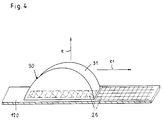
- a Velcro-type connection 25 is advantageously provided (Fig.4).
- This Velcro-type connection is designed in a manner known per se.
- a Velcro type connection 25 can also be used in other ways to be able to remove the cushion 30 from the central connecting web 120 and to be able to arrange it again in a different position, the position change being indicated by the arrow X1 in FIG. In this way, the cushion 30 can be adapted to the flexion area of the knee of the patient's leg.
- the connecting web 120 is formed by an appropriately designed fabric cut.
- the cushion 30 can also be held on the central connecting web 120 by means of a magnetic connection 125, the central connecting web 120 then carrying at least one magnet 126, while the support surface 35 or the region of the cushion 30 adjacent to the support surface 35 has a plate-like shape
- Blank 127 consists of a magnetizable material. Even with such a connection, the cushion 30 can be removed from the central connecting web 120 and can be fastened thereon in a different position. In order to keep the weight of such a magnetic connection as low as possible, it is advantageous if a plurality of small magnets 126 are provided on the connecting web 120 at intervals from one another.
- the blank 127 made of magnetizable material can be thin-walled and strip-shaped (FIG. 5). The magnetic field that is formed can be used to support healing after knee surgery.
- the side parts 15, 15 'of the sleeve 10 of the knee splint 100 each have at least one tubular rod 16, 17 running in the longitudinal direction of the knee splint as stabilizing elements (FIG. 2).
- each side part 15, 15 'of the sleeve 10 receives three tubular rods 16, 16', 16 '' and 17, 17 ', 17''which are parallel are mutually extending and the ends of which can be spoon-like and flattened.
- each side part 15, 15 'of the sleeve 10 consists of a double-walled fabric strip 19, 19', the interior of which is formed by longitudinal seams 125 in one of the Number of tubular rods 16, 16 ', 16''and 17, 17', 17 '' to be accommodated is divided into a corresponding number of pocket-shaped chambers 121.
- Receiving pockets for the rods are open on one side and can be closed by means of locking tabs.
- tubular rods 16, 16 ', 16''and 17, 17', 17 '' of the side parts 15, 15 'of the knee splint 100 do not specify the bending angle for the knee, but are expediently straight with an angle 18 in the area of the lower one Ends 15b, 15'b of the side parts 15, 15 'of the knee brace 100, that is to say in the lower calf area for better adaptation to the anatomy, so that the side parts 15, 15' are angled slightly upward in their lower areas relative to a horizontal support surface 110 (Fig.3).
- the tubular rods 16, 16 ', 16''and 17, 17', 17 '' are provided with circular cross sections, although other geometric cross-sectional shapes can also be provided.
- tubular rods 16, 16 ', 16''and 17, 17', 17 '' are made of a light metal, suitably made of aluminum or glass fiber reinforced plastic; it is also possible to design the tubular rods as carbon fiber rods. It is essential that the tubular rods are not heavy. Fully walled tubular rods can also be used. The ones used on the knee brace Despite maintaining a high degree of inherent rigidity, rods can be deformed to a certain degree in order to be able to adapt the knee brace to the contours of the leg.
- the two side parts 15, 15 'of the sleeve 10 are V-shaped and conical in the direction of the calf area (FIGS. 1 and 2).
- the connecting web 120 between the two side parts 15, 15 ' also has a V shape.
- the cushion 30 is adapted to the course of the side parts 15, 15 ′ and is conically tapered downwards in the direction of the closure band 21.
- the fastener tapes 20, 21 connecting the two side parts 15, 15 'of the sleeve 10 and the two fastener tape parts 22', 22 '' of the middle fastener tape 22 are expediently closed at their ends 20a, 20b, 21a, 21b and 22a, 22b provided with Velcro fasteners so that the length of the fastener straps 20, 21, 22 can be adjusted.
- the fastener straps 20, 21 connecting the two side parts 15, 15 'of the sleeve 10 at the end are fastened on the inner wall side to the side parts 15, 15', the middle fastener tape 22 with its fastener tape parts 22 ', 22' 'on the outer wall side of the side parts 15, 15 'is held (Fig. 1 and 2).
- the fastener tape part 22 ′ can be formed in two parts.
- the other fastener tape part 22 ′′ is preferably designed as a buckle, belt buckle 22 ′′ b. If the fastener tape part 22 'is formed in one piece, then a cushion cushion 50 is pushed onto the fastener tape part 22' (FIG. 2).
- the pillow 30 consists of an approximately semicircular Shaped body 31, which is dimensioned such that in its longitudinal cross-sectional area 32 the area of an isosceles and right-angled triangle 33 with its base 33a resting on the cushion base 35 can be placed with a center line 33d corresponding to the radius of the semicircular shaped body 31.
- the cathets of the triangular surface 33 are designated 33b, 33c.
- the base 33a of the triangular face 33 simultaneously forms the bearing surface 35 of the cushion 30.
- the opposite the base angle ⁇ is approximately 90 ° ( Figure 5).
- the shaped body 31 of the cushion 30 consists of an approximately triangular core 36 and of cushion-like and segment-like sections 37, 37 'covering these in the side area, the core 36 being larger than the hardness of the material of the cushion-like sections 37, 37' Hardness.
- These cushion-like sections 37, 37 ' are made of a suitable foam plastic, and silicone rubbers can also be used.
- the difference between the hardness of the cushion-like sections 37, 37 'and the hardness of the core 36 is at least 10 Shore A, advantageously 20 Shore A.
- the material of the cushion-like sections 37, 37' has a hardness below 50 Shore A and the material of the Kerns 36 has a hardness above 50 Shore A.
- the molded body 31 of the cushion 30 of the knee brace 100 or the cushion-like sections 37, 37 ', which partially surround the core 36 of the molded body 31, consists of a soft or soft-elastic material, such as felt, foam rubber, neoprene, rubber or of viscoelastic silicone rubber or made of an elastic, compressible, pressure-deformable silicone rubber, for example with a hardness of 40 Shore A, a silicone foam or a plastic foam with a hardness of 9 to 13 Shore A or a compressible silicone rubber of the type of a cold rubber that vulcanizes according to the process of polyaddition high flexibility has a hardness below 4 Shore A, but silicone rubbers whose hardness is above 4 Shore A can also be used.
- a soft or soft-elastic material such as felt, foam rubber, neoprene, rubber or of viscoelastic silicone rubber or made of an elastic, compressible, pressure-deformable silicone rubber, for example with a hardness of 40 Shore A,
- Such viscoelastic silicone rubbers or materials with the same elastic properties have the property of having a massaging action on the leg in the flexion area of the knee when the knee splint 100 is applied due to the sliding movement, triggered by mass displacement, when pressure is applied or during movement sequences. It is particularly advantageous for the production of the shaped body 31 to choose a material that is viscoelastic and, because of its elastic properties, brings about a massage.
- the molded body 31 consists of a core 36 with a cushioning by the sections 37, 37 '
- this core 36 which can also have a different geometric shape, consists of a hard or incompressible plastic with, for example, a hardness above 50 Shore A and has a much greater hardness than the cushion-like sections 37, 37 'in order to give the cushion 30 a certain dimensional stability.
- Natural or artificial rubber or hard rubber can be used as material for the core 36.
- a chloroprene polymer (trade name NEORPEN) with a hardness of 50 Shore A
- a rubber-elastic, cross-linked polyurethane (trade name VULKOLAN) with a hardness of 65 to 90 Shore A
- a silicone rubber with a hardness of 60 Shore A
- an ethylene -Propylene-diene rubber (EPDM) with a hardness of 80 Shore A
- a copolymer with acrylonitrile (trade name PERBUNAN) with a hardness of 70 Shore A
- PERBUNAN ethylene -Propylene-diene rubber
- PERBUNAN copolymer with acrylonitrile
- other plastics or natural product derivatives can also be used to produce the core 36. It is essential that the core 36 has sufficient hardness.
- the approximately triangular core 36 is rounded in its upper region 36a, the side cushion-like sections 37, 37 'extending over this region 36a and being able to be formed in one piece (Fig.5).
- the molded body 31 of the cushion 30 can also be formed from a sheath or a bag-like body with a shape corresponding to the cushion 30 from a plastic film, the interior of which is filled with a gel-like filler made of a plastic, e.g. a viscous silicone oil is filled, the filler having resettable and viscoelastic properties.
- a cushion 30 filled with a gaseous or other liquid medium can also be used.
Abstract
Description
Die Erfindung betrifft eine Knieschiene mit einer am Bein anzulegenden, auf der Vorderseite des Beines zusammengehaltenen Hülse.The invention relates to a knee brace with a sleeve to be placed on the leg and held together on the front of the leg.
Operative Eingriffe am Knie verlangen eine postoperative Ruhigstellung, die klassisch durch einen Funktionsgipsverband hergestellt wird. Typischerweise sind hier Kunststoff-Gipse oder Schienen anzutreffen, die mit elastischen Binden angewinkelt werden. Bei mobilen Patienten werden diese Binden häufig durch Klettbänder ersetzt, die direkt auf schalenförmigen Schienen angebracht werden. Zur Erhöhung des Tragekomforts werden diese Schalen oftmals ausgepolstert. Durch die DE-A-31 23 148 ist eine Knieschiene mit einem flexiblen Mantel bekannt, dessen Seitenränder nach dem Anlegen des Mantels an das Bein auf der Vorderseite des Beines zusammengehalten werden und je eine Aussparung für die Kniescheibe aufweisen, wobei längs dieser Seitenränder verstellbare Verschlußelemente vorgesehen sind und wobei der Mantel an den Bereichen, die nach dem Anlegen des Mantels an das Bein an den Seitenflächen und der Rückseite des Beines zu liegen kommen, mit Versteifungsstäben versehen ist. Der Mantel dieser Knieschiene ist aus mehreren anatomiegerechten Zuschnitten zusammengesetzt, wobei die Zuschnitte und die Versteifungsstäbe eine zur Fixierung des Kniegelenks in einer Beugestellung von etwa 20o bestimmte Form und Krümmung aufweisen.Surgical interventions on the knee require postoperative immobilization, which is traditionally produced by a functional plaster cast. Plastic plasters or splints that are angled with elastic bandages are typically found here. In mobile patients, these bandages are often replaced by Velcro strips that are attached directly to bowl-shaped rails. These shells are often padded to increase comfort. From DE-A-31 23 148 a knee brace with a flexible jacket is known, the side edges of which are held together after the jacket has been put on the leg on the front of the leg and each have a recess for the patella, adjustable locking elements along these side edges are provided and the jacket is provided with stiffening bars on the areas that come to rest on the side surfaces and the back of the leg after the jacket has been put on. The sheath of this knee brace is composed of several anatomically correct blanks, the blanks and the reinforcing rods have to fix the knee joint in a flexion of about 20 o particular shape and curvature.
Auch die Knieschiene nach der DE-A-42 29 044 besteht aus einem flexiblen Mantel, der an seinen Seitenrändern mit Verschlußelementen versehen ist, die den Mantel nach dem Anlegen an das Bein in Form einer geschlossenen Röhre zusammenhalten, wobei die Längsachse des den Unterschenkel umgebenden Teils eine Winkelstellung zur Längsachse des den Oberschenkel umgebenden Teils einnimmt. Bei dieser Knieschiene ist der den Mantel bildende Zuschnitt einteilig ausgebildet und in eine Ebene abwickelbar, wobei in abgewickeltem Zustand eine sich im wesentlichen parallel zur Beinlängsachse erstreckende Ausnehmung vorgesehen ist, welche längs der Beinrichtung größere Abmessungen aufweist als quer dazu. Die Ausnehmung erreicht nicht an mindestens einem ihrer Enden die jeweils nächstliegende der Kanten des Zuschnittes. Die beiden längsgerichteten Seitenkanten der Ausnehmung sind bei fertiggestellter Knieschiene miteinander verbunden.The knee brace according to DE-A-42 29 044 also consists of a flexible jacket which is provided on its side edges with closure elements which hold the jacket together in the form of a closed tube after it has been placed on the leg, wherein the longitudinal axis of the part surrounding the lower leg assumes an angular position to the longitudinal axis of the part surrounding the thigh. In the case of this knee brace, the blank forming the sheath is formed in one piece and can be unwound in one plane, wherein in the unwound state a recess is provided which extends essentially parallel to the longitudinal axis of the leg and which has larger dimensions along the device than transversely thereto. The recess does not reach the closest edge of the blank on at least one of its ends. The two longitudinal side edges of the recess are connected to one another when the knee brace is finished.
In beiden Fällen bestehen die Knieschienen aus einem flexiblen Mantel. Ist dieser Mantel aus mehreren Zuschnitten zusammengesetzt, so ist stets eine große Genauigkeit bei der Näharbeit erforderlich. Ein ungenaues Aneinanderliegen und Zusammenfügen der einzelnen Zuschnitte kann zu einer fehlerhaften Form und damit zu einem schlechten Sitz der Schiene führen. Beide bekannten Knieschienen sind so ausgebildet, daß sie das Kniegelenk in einer vorgegebenen Beugestellung von etwa 20o fixieren, wobei eine im Verlauf der Behandlung auftretende Lockerung der Knieschiene korrigierbar ist. Um diese vorgegebene Beugestellung einhalten zu können, sind die Mäntel der Knieschienen aus mehreren anatomiegerechten Zuschnitten zusammengesetzt, wobei die Zuschnitte und die Versteifungsstäbe eine zur Fixierung des Kniegelenks in einer Beugestellung von etwa 20o bestimmte Form und Krümmung aufweisen. Aufgrund der vorgegebenen, die Knieschienen bildenden Mäntel ergeben sich oftmals Paßformprobleme und Anpassungsschwierigkeiten. Letztlich müssen diese bekannten Knieschienen maßgefertigt sein. Hinzu kommt, daß auch bei stillgelegtem Knie der Patient mit den bekannten Knieschienen keine Streckübungen machen kann. Da die Mäntel dieser Knieschienen im angelegten Zustand das Bein allseitig umhüllen, ist ein Wärmestau nicht vermeidbar.In both cases, the knee braces consist of a flexible jacket. If this coat is composed of several blanks, great precision is always required when sewing. An inaccurate abutting and joining of the individual blanks can lead to an incorrect shape and thus to a poor fit of the rail. Both known knee braces are formed so that they fix o the knee in a predetermined bent position of approximately 20, with a course of treatment occurring in the loosening of the knee brace is correctable. In order to meet this predetermined flexed position, the shells of the knee braces of several anatomically correct blanks are put together, the blanks and the reinforcing rods have to fix the knee joint in a flexion of about 20 o particular shape and curvature. Due to the given shells that form the knee braces, there are often fitting problems and difficulties in adapting. Ultimately, these well-known knee braces must be custom-made. In addition, that also when the knee is not in use, the patient cannot do any stretching exercises with the known knee braces. Since the sheaths of these knee braces cover the leg on all sides when put on, heat build-up cannot be avoided.
Durch die US-A-3.831.467 ist eine Knieorthese bekannt, die aus einem elastischen Flächengebilde besteht, das hüllenartig im Kniebereich am Ober- und Unterschenkel gelegt und mittels einer Vielzahl von Verschlußbändern am Bein festgehalten wird. Das Bein wird im angelegten Zustand der Knieorthese von dieser ganz umschlossen; nur eine Öffnung für die Patella wird freigelassen. Zur Versteifung der Orthese, durch die ein Beugen des Knies verhindert werden soll, sind an dem Flächengebilde Versteifungsstäbe vorgesehen, von denen die mittleren drei Versteifungsstäbe gegenüber der Patella, also die direkt hinter der Kniekehle angeordneten Versteifungsstäbe, die wichtigtsten sind. Zusätzlich kann seitlich noch je ein Versteifungsstab vorgesehen sein. Wegen des natürlichen Hohlraumes der Kniekehle liegen die Versteifungsstäbe dort nicht am Bein an, was ein Hin- und Herrutschen der Orthese am Bein bewirken kann, auch wenn die Verschlußbänder fest angezogen sind. Aus diesem Grunde ist ein weiches Polster auf der inneren Oberfläche der Knieorhtese an dieser Stelle angebracht. Dieses Polster füllt lediglich die Kniekehle aus; es hält jedoch das Knie nicht in der für eine erfolgreiche Behandlung erforderliche Beugehaltung von 10o bis 20o, da das Polster relativ flach ausgebildet ist und lediglich zur Verminderung des Verrutschens der angelegten Orthese beitragen soll.From US-A-3,831,467 a knee orthosis is known which consists of an elastic flat structure which is placed like a sleeve in the knee area on the upper and lower leg and is held on the leg by means of a plurality of fastening straps. The leg is completely enclosed by the knee orthosis when it is in place; only one opening for the patella is left open. To stiffen the orthosis, which is intended to prevent bending of the knee, stiffening bars are provided on the fabric, of which the middle three stiffening bars opposite the patella, i.e. the stiffening bars arranged directly behind the hollow of the knee, are the most important. In addition, a stiffening rod can be provided on each side. Because of the natural hollow of the hollow of the knee, the stiffening rods do not lie there on the leg, which can cause the orthosis to slide back and forth on the leg, even if the fastener straps are tightened. For this reason, a soft pad is attached to the inner surface of the knee orthosis at this point. This cushion only fills the back of the knee; however, it does not keep the knee in the bent position of 10 o to 20 o required for successful treatment, since the pad is relatively flat and is only intended to reduce the slipping of the applied orthosis.
Aufgabe der vorliegenden Erfindung ist es, eine postoperative Knieschiene zur Ruhigstellung des Kniegelenkes zweckmäßigerweise in funktionaler leichter Beugestellung zu schaffen, die es dem Patienten ermöglicht, bei angelegter Knieschiene Streckübungen in der Schiene vorzunehmen, die eine individuelle Anpassung an verschiedene Beingrößen und -abmessungen sowie Beinkonturen ermöglicht, eine wärmestauvermeidende Konstruktion und einen hohen Tragekomfort aufweist.The object of the present invention is to create a postoperative knee splint for immobilizing the knee joint, expediently in a functional, slightly bent position, which enables the patient to perform stretching exercises in the splint with the knee brace on, which enables individual adaptation to different leg sizes and dimensions as well as leg contours, has a heat-preventing construction and is extremely comfortable to wear.
Gelöst wird diese Aufgabe durch die im Anspruch 1 angegebenen Merkmale.This object is achieved by the features specified in claim 1.
Die die erfindungsgemäße Knieschiene bildende Hülse weist auf ihrer Innenseite im Kniekehlenbereich ein bei angelegter Knieschiene das Knie in einer vorgegebenen Beugehaltung von etwa 10o bis 20o,zweckmäßigerweise von 15o bis 20o,haltendes Kissen aus einem formstabilen, kompressiblen und ein Rückstellvermögen aufweisenden Kunststoff, zweckmäßigerweise einem Schaumkunststoff oder einem anderen geeigneten Material auf, wobei das Kissen auch abnehmbar ist, um die Knieschiene auch dann einsetzen zu können, wenn das Bein in gestreckter Lage gehalten werden soll.The sleeve forming the knee splint according to the invention has a cushion made of a dimensionally stable, compressible and resilient plastic that holds the knee in a predetermined bending position of approximately 10 o to 20 o , expediently from 15 o to 20 o , when the knee splint is applied , expediently on a foam plastic or another suitable material, the cushion also being removable so that the knee brace can also be used when the leg is to be held in an extended position.
Dieses Kniebeugehaltekissen besteht aus einem etwa halbkreisförmigen Formkörper mit einer das Bein in seinem Kniekehlenbereich abstützenden Breite. Durch die Form und die Abmessungen des Kissens wird die gewünschte und erforderliche Beugehaltung erreicht.This knee flexion cushion consists of an approximately semicircular shaped body with a width supporting the leg in the area of the hollow of the knee. The shape and dimensions of the pillow achieve the desired and required bending.
Bevorzugterweise ist das Kniebeugehaltekissen so bemessen, daß in dessen Längsquerschnittsfläche die Fläche eines mit seiner Basis auf der Kissenstandfläche aufliegenden, gleichschenkligen, rechtwinkligen Dreiecks mit einer dem Radius des halbkreisförmigen Formkörpers entsprechenden Mittellinie legbar ist.The knee flexion cushion is preferably dimensioned such that in its longitudinal cross-sectional area the surface of an isosceles, right-angled triangle with its base resting on the cushion base surface can be placed with a center line corresponding to the radius of the semicircular shaped body.
Die Hülse der Knieschiene besteht zur Ausbildung einer flexiblen, jedoch stabilen Halbschale aus zwei stabilen, eine hohe Eigensteifigkeit aufweisenden Seitenteilen, die an ihren beiden Enden über je ein in der Länge verstellbares Verschlußband miteinander und mittig über einen Verbindungssteg mit in dessen seitlichen Bereich an den beiden Seitenteilen befestigten, sich zu einem mittleren Verschlußband miteinander verbindbaren Verschlußbandteilen verbunden sind, wobei an dem etwa mittigen Verbindungssteg das Kniebeugehaltekissen angeordnet ist, das in Knieschienenlängsrichtung verläuft und das mindestens eine der Kniebreite entsprechende Breite aufweist. Das Kniebeugehaltekissen ist lösbar auf der Innenseite des mittleren Verbindungssteges der schalenförmigen Hülse angeordnet und auf dem mittleren Verbindungssteg lageveränderbar gehalten, so daß eine individuelle Anpassung an den Kniebeugebereich des Beines und dessen Anatomie möglich ist.The sleeve of the knee brace is used to form a Flexible, but stable half-shell made of two stable, high inherent rigidity side parts, which were attached to each other at their two ends via a length-adjustable fastener tape and in the middle via a connecting bar with the side area on the two side parts, to form a medium fastener tape fastener parts which can be connected to one another are connected, the knee flexion cushion, which runs in the longitudinal direction of the knee brace and which has at least one width corresponding to the knee width, being arranged on the approximately central connecting web. The knee flexion cushion is detachably arranged on the inside of the central connecting web of the cup-shaped sleeve and is held in a position-changing manner on the central connecting web, so that an individual adaptation to the knee bending area of the leg and its anatomy is possible.
Die Seitenteile der Hülse weisen als stabilisierende Elemente mindestens je einen in Knieschienenlängsrichtung verlaufenden, rohrförmigen Stab auf, wobei bevorzugterweise in jedem Seitenteil der Hülse drei rohrförmige Stäbe vorgesehen sind, die parallel zueinander liegend sind. Die Anordnung der einzelnen rohrförmigen Stäbe erfolgt in taschenförmigen Kammern, die in jedem Seitenteil der Hülse ausgebildet sind, wozu jedes Seitenteil aus einem doppelwandig ausgebildeten Gewebestreifen besteht.The side parts of the sleeve have, as stabilizing elements, at least one tubular rod running in the longitudinal direction of the knee splint, three tubular rods preferably being provided in each side part of the sleeve and lying parallel to one another. The individual tubular rods are arranged in pocket-shaped chambers which are formed in each side part of the sleeve, for which purpose each side part consists of a double-walled fabric strip.
Bevorzugterweise sind die rohrförmigen Stäbe eines jeden Seitenteils der Hülse gerade verlaufend mit Abwinkelungen im unteren Wadenbereich ausgebildet. Die rohrförmigen Stäbe bestehen aus einem Leichtmetall, zweckmäßigerweise aus Aluminium, glasfaserverstärktem Kunststoff oder sind als Kohlefaserstäbe ausgebildet.The tubular rods of each side part of the sleeve are preferably designed to run straight with bends in the lower calf area. The tubular rods consist of a light metal, expediently of aluminum, glass fiber reinforced plastic or are designed as carbon fiber rods.
Eine V-förmig und konisch sich in Richtung zum Wadenbereich verlaufende Ausgestaltung der beiden Seitenteile der Hülse ermöglicht eine Anpassung an die anatomischen und biomechanischen Verhältnisse.A V-shaped and tapered configuration of the two side parts of the sleeve in the direction of the calf area enables adaptation to the anatomical and biomechanical conditions.
Es ist hiernach eine formgenähte Knie-Hülse als funktionelle Knielagerungsschiene zur Stabilisierung und Ruhigstellung des Kniegelenks in funktionaler leichter Beugestellung geschaffen. Die Knieschiene besteht aus seitlich angeordneten stabilisierenden Stäben, die über Verschlußbänder miteinander verbunden sind, wobei diese Verschlußbänder auf der Bein-Vorderseite durch überlappende Klettverschlüsse oder anderweitig ausgebildete Verschlüsse, wie Schnallen od.dgl.,verschließbar sind.According to this, a shape-sewn knee sleeve is created as a functional knee support rail for stabilizing and immobilizing the knee joint in a functional, slightly bent position. The knee brace consists of laterally arranged stabilizing bars which are connected to one another via fastening straps, these fastening straps being closable on the front of the leg by overlapping Velcro fasteners or other trained fasteners such as buckles or the like.
Das Kniebeugehaltekissen ist in der halbschalenförmig ausgebildeten Hülse aus formstabilem Schaumstoff gefertigt, um das Knie in die gewünschte leichte Beugehaltung von etwa 10o bis 20o zu bringen. Der eingesetzte Schaumstoff ist bei Kraft- und Druckanwendung kompressibel, so daß der Patient bei angelegter Knieschiene Streckübungen in der Lagerungsschiene vornehmen kann. Ohne Kraftausübung wird das Bein wieder in eine leichte Beugehaltung zurückversetzt. Das Kissen mit polsterartiger Wirkung wird mit einem Klettband variabel, d.h. längenverstellbar, an der Innenseite der schalenförmigen Hülse befestigt, um individuell richtig plaziert werden zu können. Beim aufrechten Patienten verhindert das Kissen durch Abstützung an der Unterschenkelmuskulatur zudem das Rutschen der Knieschiene.The squat holding pad is made in the half-shell-shaped sleeve made of dimensionally stable foam, in order to bring the knee in the desired light bent posture of about 10 o to 20 o. The foam used is compressible when force and pressure are applied, so that the patient can perform stretching exercises in the positioning rail with the knee brace on. Without exerting force, the leg is put back into a slight bending position. The cushion with a cushion-like effect is attached to the inside of the bowl-shaped sleeve with a Velcro strap, ie adjustable in length, so that it can be placed correctly and individually. In the case of an upright patient, the pillow prevents the knee splint from slipping by being supported on the lower leg muscles.
Nach dem bei schweren Knie-Orthesen auf dem Markt allgemein gebräuchlichem Prinzip läßt sich eine Stabilisierung des Knies durch Fixierung an drei Punkten erreichen:
Zwei Stellen an der Rückseite des Beines, am Ober- und Unterschenkel, eine Stelle an der Vorderseite des Beines, an der Tibia knapp unterhalb der Patella.Dementsprechend sind die rückwärtigen Verschlußbänder am Ober- und Unterschenkel sowie das vordere,mittige Verschlußband kräftig ausgebildet und fest mit den seitlichen Stabilisierungselementen verbunden. Diese feste Verankerung ist entscheidend für die Funktionsfähigkeit der Knieschiene.According to the principle commonly used on the market for heavy knee orthoses, stabilization of the knee can be achieved by fixation at three points:
Two places on the back of the leg, on the thigh and lower leg, one place on the front of the leg, on the tibia just below the patella. Accordingly, the rear fastening straps on the thigh and lower leg as well as the front, central fastening band are strong and firm connected to the side stabilization elements. This firm anchoring is crucial for the functionality of the knee brace.
Die seitlichen Stabilisierungselemente bzw. die seitlichen rohrförmigen Stäbe geben den Beugewinkel des Knies nicht vor, sondern sind bevorzugterweise gerade ausgebildet mit einer Abwinklung im unteren Wadenbereich zur besseren Anpassung an die Anatomie. Diese Stabilisierungsstäbe sind nachformbar zur individuellen Anpassung der Knieschiene.The lateral stabilizing elements or the lateral tubular rods do not specify the bending angle of the knee, but are preferably straight with a bend in the lower calf area for better adaptation to the anatomy. These stabilizing bars can be reshaped for individual adjustment of the knee brace.
Bei den bekannten Knieschienen ist das Gegenteil der Fall. Soweit Schienen verwendet werden, geben hier die Schienen den Beugewinkel vor und der Formkörper der Knieschiene folgt diesem. Das erfordert aufwendiges Formschneidern und verursacht Paßformprobleme. Bei der erfindungsgemäßen Knieschiene wird dies bei gerader Knieschienenform mit dem eingelegten Kniebeugehaltekissen einfach gelöst.The opposite is the case with the known knee braces. As far as splints are used, the splints specify the bending angle and the molded body of the knee splint follows this. This requires elaborate shape cutting and causes fitting problems. In the knee brace according to the invention, this is simply solved with the knee brace cushion inserted in a straight knee brace shape.
Die seitlichen Stabiliserungsstäbe der Hülse sind rund ausgebildet, mehrfach angeordnet und besitzen so bei leichtem Gewicht und einfacher Konstruktion eine sehr gute stabilisierende Wirkung.The side stabilizing rods of the sleeve are round, arranged several times and thus have a very good stabilizing effect with a light weight and simple construction.
Die Knieschiene besteht somit aus einer Grundkonstruktion mit zwei stabilen Seitenteilen, die unten und oben durch Verschlußbänder miteinander verbunden sind. Durch diese Konstruktion entsteht eine flexible, jedoch stabile Halbschale, in die das Bein gelegt werden kann. Nach Anbringen der Verschlüsse wird eine das Bein umgebende Hülse geschaffen. Zur Beugung des Knies wird in dieser halbschalenartig ausgebildeten Hülse das Kniekissen angebracht. Die Stabilisierung des Knies wird durch das vordere Verschlußband unterhalb der Patella in Verbindung mit dieser halbschalenartigen Hülse erreicht.The knee brace thus consists of a basic construction with two stable side parts, which are connected at the top and bottom by fastener straps. This construction creates a flexible but stable half-shell, in which the leg can be placed. After attaching the fasteners, a sleeve surrounding the leg is created. In order to bend the knee, the knee cushion is attached in this half-shell-like sleeve. The stabilization of the knee is achieved by the front closure band below the patella in connection with this half-shell-like sleeve.
Mit der erfindungsgemäß ausgebildeten Knieschiene werden folgende Vorteile erreicht:
- Eine sehr offene Konstruktion ohne Wärmestau.
- Eine gute Stabilisierung des Knies.
- Einfache Handhabung durch wenige Verschlüsse.
- Gute Paßform und geringes Gewicht.
- Durch das Kissen in der Kniekehle , das sich an der Wade abstützt, wird das Abrutschen der Knieschiene am Bein nach unten verhindert.
- Das Strecken des Beins aus der durch das Kissen vorgegebenen Beugung ist durch die Nachgiebigkeit des Kniebeugehalte- bzw. Kniekehlenkissens möglich, z.B. zur Krankengymnastik.
- Die Knieschiene kann problemlos am liegenden Patienten geöffnet werden; das Bein wird durch das Kissen ähnlich einer Knierolle gebeugt gelagert.
- Durch die Rohre in den Seitenteilen anstelle eines stabilen Stabs formt sich die Knieschiene dem Bein besser an.
- Die Stabilisierungsrohre können einfach gebogen werden, um die Knieschiene, falls erforderlich, genau anzupassen.
- Die Operationswunden werden nicht von einer Bandage abgedeckt.
- A very open construction without heat build-up.
- A good stabilization of the knee.
- Easy handling due to few closures.
- Good fit and light weight.
- The cushion in the hollow of the knee, which is supported on the calf, prevents the knee splint from slipping down on the leg.
- The leg can be stretched out of the flexion predetermined by the pillow due to the flexibility of the knee flexion or deep-throat pillow, eg for physiotherapy.
- The knee brace can be easily opened when the patient is lying down; the leg is bent by the pillow like a knee roll.
- Thanks to the tubes in the side parts instead of a sturdy bar, the knee brace is better shaped to the leg.
- The stabilizing tubes can be easily bent to adjust the knee brace if necessary.
- The surgical wounds are not covered by a bandage.
Als postoperative Knieschiene bietet diese eine hohe Therapiesicherheit. Das Knie ist immobilisierbar und definiert zu stabilisieren. Ein anhaltender, gleichbleibender Stabilisierungseffekt wird erreicht. Das Knie wird in einer definierten, leichten Beugestellung ruhiggestellt, die das vordere Kreuzband entspannt. Die Knieschiene sitzt gut am Bein an und ist drehstabil verankert. Eine gute Weichteilabstützung wird am Unterschenkel erreicht. Die Knieschiene läßt sich unterschiedlichen Ober- und Unterschenkelweiten anpassen.As a postoperative knee brace, it offers a high level of therapeutic safety. The knee is immobilizable and defined too stabilize. A lasting, constant stabilizing effect is achieved. The knee is immobilized in a defined, slight flexion position that relaxes the anterior cruciate ligament. The knee brace fits snugly on the leg and is anchored in a torsionally stable manner. Good soft tissue support is achieved on the lower leg. The knee brace can be adjusted to different thigh and lower leg widths.
Mit dieser Knieschiene wird ein hoher Tragekomfort erhalten, denn die Knieschiene scheuert nicht, schnürt nicht ein, trägt wenig auf, ist sehr leicht aufgrund des geringen Gewichtes; sie ist hautfreundlich, luft- und wasserdampfdurchlässig und hat keine unangenehme Wärmewirkung. Die Knieschiene läßt sich einfach anlegen. Der Heilungsprozeß ist gut kontrollierbar. Eine postoperative Wundversorgung ist möglich. Durch Verwendung geeigneter Materialien ist die Knieschiene schmutzunempfindlich.This knee brace is very comfortable to wear, because the knee brace does not rub, does not constrict, does not wear much, is very light due to its low weight; it is skin-friendly, permeable to air and water vapor and has no unpleasant heat effect. The knee brace is easy to put on. The healing process is easy to control. Postoperative wound care is possible. By using suitable materials, the knee brace is insensitive to dirt.
Weiterentwicklungen der Erfindung sind Gegenstand der Unteransprüche.Further developments of the invention are the subject of the dependent claims.
Ausführungsbeispiele der Erfindung sind in den Zeichnungen dargestellt. Es zeigt
- Fig. 1 eine Ansicht von oben auf die Innenseite der entfalteten Knieschiene,
- Fig. 2 eine Ansicht von oben auf die Außenseite der entfalteten Knieschiene,
- Fig. 3 einen senkrechten Längsschnitt gemäß Linie III-III in Fig. 1,
- Fig. 4 in einer schaubildlichen Ansicht einen Abschnitt der Knieschiene mit dem Kniebeugehaltekissen und
- Fig. 5 eine Seitenansicht des Kniebeugehaltekissens in natürlicher Größe.
- 1 is a top view of the inside of the unfolded knee brace,
- 2 is a top view of the outside of the unfolded knee brace,
- 3 shows a vertical longitudinal section according to line III-III in FIG. 1,
- Fig. 4 is a perspective view of a portion of the knee brace with the squat cushion and
- Fig. 5 is a side view of the natural size squat cushion.
Gemäß Fig. 1 und 2 besteht die Knieschiene 100 aus einer am Bein eines Patienten anzulegenden und auf der Vorderseite des Beines zusammengehaltenen Hülse 10, die auf ihrer Innenseite 11 im Kniekehlenbereich des Beines ein bei angelegter Knieschiene 100 das Knie in einer vorgegebenen Beugehaltung von etwa 10o bis 20o, zweckmäßigerweise von 15o bis 20o oder von 15o oder 20o, haltendes Kissen 30 aufweist. Dieses Kniebeugehalte- bzw. -polsterkissen 30 besteht aus einem formstabilen, kompressiblen und ein Rückstellvermögen aufweisenden Kunststoff, zweckmäßigerweise aus einem Schaumkunststoff. Als Schaumkunststoff werden offen- oder geschlossenzellige Schaumkunststoffe mit einem entsprechenden Verformungswiderstand eingesetzt. Bevorzugterweise werden Schaumkunststoffe aus PUR,PVC und PE eingesetzt. Auch andere geeignete,die gleichen Eigenschaften aufweisenden Materialien können eingesetzt werden. Die Hülse 10 zur Ausbildung einer flexiblen, jedoch stabilen Halbschale besteht aus zwei stabilen, eine hohe Eigensteifigkeit aufweisenden, den Beinkonturen anpaßbaren Seitenteilen 15,15', die an ihren beiden Enden 15a,15'a und 15b,15'b über je ein in der Länge verstellbares Verschlußband 20,21 miteinander und mittig über einen Verbindungssteg 120 verbunden sind. An bzw. auf dem mittigen Verbindungssteg 120, und zwar im Bereich zwischen den beiden Seitenteilen 15, 15' ist das Kissen 30 angeordnet, das in Knieschienenlängsrichtung verläuft und das zweckmäßigerweise etwa eine der Kniebreite des Beines des Patienten entsprechende Breite aufweist.Im Bereich des Verbindungssteges 120 sind zu dessen beiden Seiten,bevorzugterweise an den Außenrändern, die beiden Verschlußbandteile 22'22'' eines weiteren mittigen Verschlußbandes 22 angebracht, wobei sich die beiden Verschlußbandteile 22',22'' zu dem Verschlußband 22 ergänzen (Fig.1).According to FIGS. 1 and 2, the
Nach einer Ausführungsform kann das Kissen 30 fest auf der Innenseite 22c des mittleren Verbindungssteges 120 der Knieschiene 100 angeordnet sein, so daß das Kissen 30 auf der Innenseite 11 der Knieschiene zu liegen kommt.According to one embodiment, the
Zweckmäßigerweise ist jedoch nach einer weiteren Ausführungsform das Kissen 30 lösbar auf der Innenseite 22c des mittleren Verbindungssteges 120 der Knieschiene 100 angeordnet. Die Länge des mittleren Verbindungssteges 120 ist dabei gegenüber der Länge des Kissens 30 größer bemessen, so daß das Kissen 30 auf dem mittleren Verbindungssteg 120 lageveränderlich, d.h. in verschiedenen Positionen, gehalten werden kann (Fig.1,3 und 4). Durch die abnehmbare Anordnung des Kissens an dem mittleren Verbindungssteg besteht die Möglichkeit, die Knieschiene auch ohne Kissen einsetzen zu können, was immer dann der Fall sein wird, wenn das Bein in gestreckter Lage gehalten werden soll.However, according to a further embodiment, the
Um das Kissen 30 vom mittleren Verbindungssteg 120 in Pfeilrichtung X abnehmen zu können und wiederum auf dem mittleren Verbindungssteg 120 befestigen zu können, um das Kissen 30 auf diesem Verbindungssteg 120 in einer anderen Position benachbart zum oberen Ende oder zum unteren Ende der Knieschiene 100 befestigen zu können, ist zweckmäßigerweise eine klettverschlußartige Verbindung 25 vorgesehen (Fig.4). Diese klettverschlußartige Verbindung ist in an sich bekannter Weise ausgebildet. Anstelle einer klettverschlußartigen Verbindung 25 können auch anderweitig ausgebildete Verbindungsmittel eingesetzt werden, um das Kissen 30 von dem mittleren Verbindungssteg 120 abnehmen und in anderer Position wieder anordnen zu können, wobei die Lageveränderbarkeit durch den Pfeil X1 in Fig.4 angedeutet ist. Auf diese Weise ist eine Anpassung des Kissens 30 an den Beugebereich des Knies des Beines des Patienten möglich. Der Verbindungssteg 120 wird von einem entsprechend gestalteten Gewebezuschnitt gebildet.In order to be able to remove the
Nach einer weiteren Ausführungsform kann das Kissen 30 auch auf dem mittleren Verbindungssteg 120 mittels einer Magnetverbindung 125 gehalten sein, wobei dann der mittlere Verbindungssteg 120 mindestens einen Magneten 126 trägt, während die Auflagefläche 35 oder der der Auflagefläche 35 benachbarte Bereich des Kissens 30 mit einem plattenförmigen Zuschnitt 127 aus einem magnetisierbaren Material besteht. Auch mit einer derartigen Verbindung ist das Kissen 30 von dem mittleren Verbindungssteg 120 abnehmbar und in anderer Position auf diesem befestigbar. Um das Gewicht einer derartigen Magnetverbindung möglichst gering zu halten, ist es vorteilhaft, wenn an dem Verbindungssteg 120 in Abständen voneinander mehrere kleine Magneten 126 vorgesehen sind. Der Zuschnitt 127 aus magnetisierbarem Material kann dünnwandig und streifenförmig ausgebildet sein (Fig.5). Das dabei ausausgebildete Magnetfeld kann zur Unterstützung der Heilung nach operativen Eingriffen am Knie herangezogen werden.According to a further embodiment, the
Die Seitenteile 15,15' der Hülse 10 der Knieschiene 100 weisen als stabilisierende Elemente mindestens je einen in Knieschienenlängsrichtung verlaufenden rohrförmigen Stab 16,17 auf (Fig.2). Nach einer bevorzugten Ausführungsform nimmt jedes Seitenteil 15,15' der Hülse 10 drei rohrförmige Stäbe 16,16',16'' und 17,17',17'' auf, die parallel zueinander verlaufend sind und deren Enden löffelartig und abgeflacht ausgebildet sein können. Zur Aufnahme dieser rohrförmigen Stäbe 16,16',16'' und 17,17',17'' besteht jedes Seitenteil 15,15' der Hülse 10 aus einem doppelwandig ausgebildeten Gewebestreifen 19,19', dessen Innenraum durch Längsnähte 125 in eine der Anzahl der aufzunehmenden rohrförmigen Stäbe 16,16',16'' und 17,17',17'' entsprechende Anzahl von taschenförmigen Kammern 121 unterteilt ist.Zur Entnahme der Stäbe, z.B. zwecks Austausch gegen Stäbe mit anderen technischen und elastischen Eigenschaften, sind die Aufnahmetaschen für die Stäbe einseitig offen ausgebildet und mittels Verschlußlaschen verschließbar.The
Diese rohrförmigen Stäbe 16,16',16'' und 17,17',17'' der Seitenteile 15,15' der Knieschiene 100 geben den Beugewinkel für das Knie nicht vor, sondern sind zweckmäßigerweise geradlinig mit einer Abwinkelung 18 im Bereich der unteren Enden 15b,15'b der Seitenteile 15,15' der Knieschiene 100, also im unteren Wadenbereich zur besseren Anpassung an die Anatomie ausgebildet, so daß die Seitenteile 15,15' in ihren unteren Bereichen gegenüber einer waagerechten Auflagefläche 110 leicht nach oben abgewinkelt sind (Fig.3). Des weiteren sind die rohrförmigen Stäbe 16, 16',16'' und 17,17',17'' mit kreisförmigen Querschnitten versehen, wobei jedoch auch andere geometrische Querschnittsformen vorgesehen sein können. Des weiteren bestehen die rohrförmigen Stäbe 16,16',16'' und 17,17',17'' aus einem Leichtmetall, zweckmäßigerweise aus Aluminium oder glasfaserverstärktem Kunststoff; auch eine Ausbildung der rohrförmigen Stäbe als Kohlefaserstäbe ist möglich. Wesentlich ist, daß die rohrförmigen Stäbe kein hohes Gewicht aufweisen. Auch vollwandig ausgebildete rohrförmige Stäbe können eingesetzt werden. Die bei der Knieschiene eingesetzten Stäbe sind trotz Beibehaltung einer hohen Eigensteifigkeit in einem gewissen Grade verformbar, um die Knieschiene den Konturen des Beines anpassen zu können.These
Die beiden Seitenteile 15,15' der Hülse 10 sind V-förmig und konisch in Richtung zum Wadenbereich verlaufend ausgebildet (Fig.1 und 2). Der Verbindungssteg 120 zwischen den beiden Seitenteilen 15,15' weist ebenfalls eine V-Form auf. Das Kissen 30 ist dem Verlauf der Seitenteile 15,15' angepaßt und ist konisch sich nach unten in Richtung zu dem Verschlußband 21 verjüngend ausgebildet.The two
Die die beiden Seitenteile 15,15' der Hülse 10 miteinander verbindenden Verschlußbänder 20,21 und die beiden Verschlußbandteile 22',22'' des mittleren Verschlußbandes 22 sind an ihren Enden 20a,20b,21a,21b und 22a,22b mit Verschlüssen, zweckmäßigerweise mit Klettverschlüssen versehen, so daß eine Längenverstellbarkeit der Verschlußbänder 20,21,22 gegeben ist. Die die beiden Seitenteile 15,15' der Hülse 10 endseitig verbindenden Verschlußbänder 20,21 sind nach einer bevorzugten Ausführungsform innenwandseitig an den Seitenteilen 15, 15' befestigt, wobei das mittlere Verschlußband 22 mit seinen Verschlußbandteilen 22',22'' außenwandseitig an den Seitenteilen 15,15' gehalten ist (Fig.1 und 2). Um ein Einschnüren des angelegten mittleren Verschlußbandes 22 am Patientenbein zu verhindern, kann das Verschlußbandteil 22' zweiteilig ausgebildet sein. Das andere Verschlußbandteil 22'' ist bevorzugterweise als Schnalle , Gurtschnalle 22''b ausgebildet. Ist das Verschlußbandteil 22' einteilig ausgebildet, dann ist auf das Verschlußbandteil 22' ein Polsterkissen 50 aufgeschoben (Fig.2).The
Das Kissen 30 besteht aus einem etwa halbkreisförmigen Formkörper 31, der so bemessen ist, daß in dessen Längsquerschnittsfläche 32 die Fläche eines mit seiner Basis 33a auf der Kissenstandfläche 35 aufliegenden, gleichschenkligen und rechtwinkligen Dreiecks 33 mit einer dem Radius des halbkreisförmigen Formkörpers 31 entsprechenden Mittellinie 33d legbar ist. Die Katheten der Dreiecksfläche 33 sind mit 33b,33c bezeichnet. Die Basis 33a der Dreiecksfläche 33 bildet gleichzeitig die Auflagefläche 35 des Kissens 30. Der der Basis gegenüberliegende Winkel α beträgt in etwa 90o (Fig.5).The
Nach einer weiteren Ausführungsform besteht der Formkörper 31 des Kissens 30 aus einem etwa dreieckförmigen Kern 36 und aus diesen im Seitenbereich abdeckenden polsterartigen und segmentartigen Abschnitten 37,37', wobei der Kern 36 eine gegenüber der Härte des Materials der polsterartigen Abschnitte 37,37' größere Härte aufweist. Diese polsterartigen Abschnitte 37,37' bestehen aus einem geeigneten Schaumkunststoff, wobei auch Silikonkautschuke eingesetzt werden können. Die Differenz zwischen der Härte der polsterartigen Abschnitte 37,37' und der Härte des Kerns 36 beträgt mindestens 10 Shore A, zweckmäßigerweise 20 Shore A. Das Material der polsterartigen Abschnitte 37,37' weist eine unterhalb 50 Shore A liegende Härte und das Material des Kerns 36 eine oberhalb 50 Shore A liegende Härte auf.According to a further embodiment, the shaped
Der Formkörper 31 des Kissens 30 der Knieschiene 100 bzw. die polsterartigen Abschnitte 37,37', die abschnittsweise den Kern 36 des Formkörpers 31 umgeben, besteht aus einem weichen oder weichelastischen Material, wie Filz, Moosgummi, Neopren, Gummi oder aus viskoelastischem Silikonkautschuk oder aus einem elastisch, kompressiblen, durch Druck verformbaren Silikonkautschuk, z.B. mit einer Härte von 40 Shore A, einem Silikonschaum bzw. einem Kunststoffschaum mit einer Härte von 9 bis 13 Shore A oder einem kompressiblen, durch Druck verformbaren und ohne Sprungelastizität in seine Form sich rückbildenden Silikonkautschuk vom Typ eines nach dem Verfahren der Polyaddition vulkanisierenden Kaltkautschuks, der neben einer hohen Flexibilität eine unter 4 Shore A liegende Härte aufweist, wobei jedoch auch Silikonkautschuke eingesetzt werden können, deren Härte oberhalb von 4 Shore A liegt. Derartige viskoelastische Silikonkautschuke oder Materialien mit gleichen Elastizitätseigenschaften besitzen die Eigenschaft, bei angelegter Knieschiene 100 aufgrund der gleitenden Bewegung, ausgelöst durch Masseverschiebung,bei Druckanwendung oder bei Bewegungsabläufen, im Beugebereich des Knies massierend auf das Bein zu wirken. Besonders vorteilhaft ist es für die Herstellung des Formkörpers 31, ein Material zu wählen, welches viskoelastisch ist und aufgrund seiner elastischen Eigenschaften eine Massage bewirkt.The molded
Besteht der Formkörper 31 aus einem Kern 36 mit einer Abpolsterung durch die Abschnitte 37,37', dann besteht dieser Kern 36, der auch eine andere geometrische Form aufweisen kann, aus einem harten oder inkompressiblen Kunststoff mit z.B. einer über 50 Shore A liegenden Härte und weist gegenüber den polsterartigen Abschnitten 37,37' eine weitaus größere Härte auf, um dem Kissen 30 eine gewisse Formstabilität zu geben. Als Material für den Kern 36 kommt natürlicher oder künstlicher Kautschuk oder Hartgummi infrage. So kann u.a. ein Chloropren-Polymerisat (Handelsname NEORPEN) mit einer Härte von 50 Shore A, ein gummielastisches, vernetztes Polyurethan (Handelsname VULKOLAN) mit einer Härte von 65 bis 90 Shore A, ein Silikonkautschuk mit einer Härte von 60 Shore A, ein Ethylen-Propylen-Dien-Kautschuk (EPDM) mit einer Härte von 80 Shore A oder ein Copolymerisat mit Acrylnitril (Handelsname PERBUNAN) mit einer Härte von 70 Shore A, ferner ein Polyamid verwendet werden. Jedoch auch andere Kunststoffe oder Naturstoffabkömmlinge können zur Herstellung des Kerns 36 herangezogen werden. Wesentlich ist, daß der Kern 36 eine ausreichende Härte aufweist.If the molded
Um eine gute Abpolsterung eines mit einem Kern 36 versehenen Kissens 30 im Kniebeugebereich zu erhalten, ist der etwa dreieckförmige Kern 36 in seinem oberen Bereich 36a abgerundet, wobei die seitlichen polsterartigen Abschnitte 37,37' sich über diesen Bereich 36a erstrecken und einstückig ausgebildet sein können (Fig.5).In order to obtain a good cushioning of a
Der Formkörper 31 des Kissens 30 kann auch aus einer Hülle oder einem beutelartigen Körper mit einer dem Kissen 30 entsprechenden Form aus einer Kunststoffolie gebildet sein, deren Innenraum mit einem gelartigen Füllmittel aus einem Kunststoff, z.B. einem zähflüssigen Silikonöl, gefüllt ist, wobei das Füllmittel rückstellbare und viskoelastische Eigenschaften aufweist. Auch ein mit einem gasförmigen oder einem anderen flüssigen Medium gefülltes Kissen 30 kann zur Anwendung gelangen.The molded
Claims (20)
Applications Claiming Priority (2)
| Application Number | Priority Date | Filing Date | Title |
|---|---|---|---|
| DE4411469A DE4411469C2 (en) | 1994-04-01 | 1994-04-01 | Knee brace with sleeve to be placed on the leg and pillow in the knee area |
| DE4411469 | 1994-04-01 |
Publications (2)
| Publication Number | Publication Date |
|---|---|
| EP0674889A1 true EP0674889A1 (en) | 1995-10-04 |
| EP0674889B1 EP0674889B1 (en) | 1998-12-09 |
Family
ID=6514495
Family Applications (2)
| Application Number | Title | Priority Date | Filing Date |
|---|---|---|---|
| EP95103917A Expired - Lifetime EP0674889B1 (en) | 1994-04-01 | 1995-03-17 | Knee-brace |
| EP95104632A Expired - Lifetime EP0677282B1 (en) | 1994-04-01 | 1995-03-29 | Knee splint |
Family Applications After (1)
| Application Number | Title | Priority Date | Filing Date |
|---|---|---|---|
| EP95104632A Expired - Lifetime EP0677282B1 (en) | 1994-04-01 | 1995-03-29 | Knee splint |
Country Status (5)
| Country | Link |
|---|---|
| US (1) | US5782785A (en) |
| EP (2) | EP0674889B1 (en) |
| AT (2) | ATE174206T1 (en) |
| DE (3) | DE4411469C2 (en) |
| ES (2) | ES2124451T3 (en) |
Cited By (1)
| Publication number | Priority date | Publication date | Assignee | Title |
|---|---|---|---|---|
| DE19817628A1 (en) * | 1998-04-21 | 1999-11-11 | Schuett & Grundei Orthopaedie | Modular knee support orthosis for fast treatment of patients |
Families Citing this family (44)
| Publication number | Priority date | Publication date | Assignee | Title |
|---|---|---|---|---|
| US8455710B2 (en) | 1997-09-22 | 2013-06-04 | Argentum Medical, Llc | Conductive wound dressings and methods of use |
| US8801681B2 (en) | 1995-09-05 | 2014-08-12 | Argentum Medical, Llc | Medical device |
| US6861570B1 (en) | 1997-09-22 | 2005-03-01 | A. Bart Flick | Multilayer conductive appliance having wound healing and analgesic properties |
| US5814094A (en) | 1996-03-28 | 1998-09-29 | Becker; Robert O. | Iontopheretic system for stimulation of tissue healing and regeneration |
| US7214847B1 (en) | 1997-09-22 | 2007-05-08 | Argentum Medical, L.L.C. | Multilayer conductive appliance having wound healing and analgesic properties |
| DE19605734C2 (en) * | 1996-02-16 | 2000-01-20 | Beiersdorf Ag | Knee joint orthosis with different lateral and medial orthotic joint |
| DE29702186U1 (en) * | 1997-02-08 | 1997-04-24 | Medi Bayreuth Weihermueller Un | Orthopedic splint |
| DE19835324A1 (en) * | 1998-08-05 | 2000-02-10 | Bayer Ag | Cyclopentabenzofuran derivatives and their use |
| US6436066B1 (en) | 2000-02-03 | 2002-08-20 | Robert Lockhart | Truss body joint brace |
| US6524265B2 (en) | 2001-04-27 | 2003-02-25 | Theodore B. Hogg | Leg brace support structure |
| US6764457B2 (en) | 2001-04-27 | 2004-07-20 | Hogg Theodore B | Leg brace support structure |
| DE10132754A1 (en) * | 2001-07-10 | 2003-01-30 | Wws Ideen Aus Pu Gmbh | Orthesis consists of interlinked plastic casings lined inside with foam layer of cellulose rubber with protuberances and support layer |
| US7488300B2 (en) | 2002-02-15 | 2009-02-10 | Thusane | Bicentric hinge for use in a brace |
| US6971996B2 (en) * | 2003-06-30 | 2005-12-06 | Thuasne | Power packs for use with bicentric hinges |
| US7150721B2 (en) * | 2003-06-30 | 2006-12-19 | Thuasne | Knee brace with dynamic counterforce |
| US7063101B2 (en) * | 2003-08-01 | 2006-06-20 | Stant Manufacturing Inc. | Fuel tank vent system |
| US20050273025A1 (en) * | 2004-05-19 | 2005-12-08 | Houser Guy M | Braces having an assembly for exerting a manually adjustable force on a limb of a user |
| US7621881B2 (en) * | 2004-07-22 | 2009-11-24 | Nordt Development Co., Llc | Donning potentiating support with expandable framework spanning hinge joint |
| US7618386B2 (en) * | 2004-07-22 | 2009-11-17 | Nordt Development Co., Llc | Two-component compression collar clamp for arm or leg |
| US7708708B2 (en) * | 2004-07-22 | 2010-05-04 | Nordt Development Co., Ltd. | Donning potentiating support with expandable framework fastened to garment |
| US7704219B2 (en) | 2004-07-22 | 2010-04-27 | Nordt Development Company, Llc | Wrist support |
| US8162867B2 (en) | 2004-07-22 | 2012-04-24 | Nordt Development Co., Llc | Body support for spanning a hinge joint of the body comprising an elastically stretchable framework |
| US7615022B2 (en) * | 2004-07-22 | 2009-11-10 | Nordt Development Co., Llc | Potentiating support with alignment opening for joint protuberance |
| US7615023B2 (en) * | 2004-07-22 | 2009-11-10 | Nordt Development Co., Llc | Donning support with framework fastened to garment |
| US7615021B2 (en) * | 2004-07-22 | 2009-11-10 | Nordt Development Co., Llc | Clothing having expandable framework |
| US7615019B2 (en) * | 2004-07-22 | 2009-11-10 | Nordt Development Co., Llc | Potentiating support with side struts spanning hinge joint |
| US7618389B2 (en) * | 2004-07-22 | 2009-11-17 | Nordt Development Co., Llc | Potentiating support with expandable framework |
| US7615027B2 (en) * | 2004-07-22 | 2009-11-10 | Nordt Development Co., Llc | Support with framework fastened to garment |
| US7637884B2 (en) * | 2004-07-22 | 2009-12-29 | Nordt Development Co., Llc | Shirt, pants and jumpsuit having expandable framework |
| US7615020B2 (en) * | 2004-07-22 | 2009-11-10 | Nordt Development Co., Llc | Support with removable pressure/alignment ring |
| FR2875400B1 (en) * | 2004-09-22 | 2007-06-15 | Gibaud Soc Par Actions Simplif | POLYCENTRIC RIGID RIGID ORTHESIS WITH ADJUSTABLE AMPLITUDE ADAPTABLE TO ANY TYPE OF MORPHOLOGY |
| US20070129776A1 (en) * | 2005-10-20 | 2007-06-07 | Light Sciences Llc | External wearable light therapy treatment systems |
| WO2008097310A1 (en) * | 2007-02-06 | 2008-08-14 | Medical Devices, Llc | Aquatic stabilizer apparatus |
| US8043242B2 (en) | 2008-06-16 | 2011-10-25 | Thermotek, Inc. | Method of and system for joint therapy and stabilization |
| US8660656B2 (en) * | 2009-10-16 | 2014-02-25 | Hanger, Inc. | Cuff assembly |
| WO2015018340A1 (en) * | 2013-08-09 | 2015-02-12 | Luo Yun | Knee joint orthosis having offloading function |
| CN105963105B (en) * | 2016-07-11 | 2018-04-17 | 江苏大学 | A kind of knee joint mechanism of decompressor |
| CN106073963B (en) * | 2016-07-11 | 2018-04-17 | 江苏大学 | A kind of knee joint flexibility mechanism of decompressor |
| JP6912208B2 (en) * | 2017-01-19 | 2021-08-04 | トヨタ自動車株式会社 | Walking aid |
| CN107049584A (en) * | 2017-05-25 | 2017-08-18 | 黄英丽 | A kind of knuckle fixed appliance |
| US20220015953A1 (en) * | 2018-12-06 | 2022-01-20 | Pankajkumar CHHATRALA | An adjustable limb stabilization device |
| CN111202949A (en) * | 2020-01-16 | 2020-05-29 | 四川大学华西医院 | Knee joint muscle strength training device and using method thereof |
| US11918500B1 (en) | 2020-03-31 | 2024-03-05 | Preferred Prescription, Inc. | Hinged knee brace with double upper strap arrangement |
| CN112107406B (en) * | 2020-07-30 | 2021-05-04 | 胡静文 | Bionic rehabilitation training device for bone joint movement |
Citations (5)
| Publication number | Priority date | Publication date | Assignee | Title |
|---|---|---|---|---|
| US3831467A (en) * | 1973-03-16 | 1974-08-27 | R Moore | Knee brace |
| US4111194A (en) * | 1976-12-27 | 1978-09-05 | Rollin Webb Cox | Posterior knee immobilizing brace |
| US4505269A (en) * | 1983-07-21 | 1985-03-19 | Davies John R | Ankle splint |
| DE3925007C1 (en) * | 1989-07-28 | 1990-09-06 | Wolfgang 6920 Sinsheim De Moch | Bandage for protecting knee joint - has PVC inner chamber with adjustable air pressure by pump action and vent valve |
| EP0496071A1 (en) * | 1991-01-24 | 1992-07-29 | Beiersdorf Aktiengesellschaft | Joint bandage |
Family Cites Families (16)
| Publication number | Priority date | Publication date | Assignee | Title |
|---|---|---|---|---|
| GB1414138A (en) * | 1972-01-25 | 1975-11-19 | Drew J | Splint and splint frame carrying case |
| US4090508A (en) * | 1977-03-15 | 1978-05-23 | Medical Specialties, Incorporated | Orthopedic knee brace |
| US4130115A (en) * | 1977-05-02 | 1978-12-19 | Taylor Glenn N | Brace hinge |
| DE3123148A1 (en) * | 1981-06-11 | 1982-12-30 | Hans-Dietrich Dr. 3501 Ahnatal Hildebrandt | KNEE RAIL |
| FR2566850B1 (en) * | 1984-06-28 | 1987-10-02 | Biron Patrick | DEVICE FOR LOCKING AND UNLOCKING IN A POSITION OF TWO MOUNTED ORGANS PIVOTING IN RELATION TO THE OTHER AND APPLICATION TO THE REALIZATION OF ORTHESES OF THE LOWER LIMBS |
| US4624246A (en) * | 1985-11-01 | 1986-11-25 | Krikor Ajemian | Knee-supporting brace |
| US4681097A (en) * | 1986-01-23 | 1987-07-21 | Pansiera Timothy T | Orthopedic brace |
| DE3610193A1 (en) * | 1986-03-26 | 1987-10-01 | Johann Dipl Ing Dr I Neuhauser | Apparatus for skiing |
| FR2600247B1 (en) * | 1986-06-20 | 1988-09-09 | Cadoret Alain J B | ORTHOPEDIC APPARATUS FOR UNSTABLE KNEE |
| DE3738664A1 (en) * | 1987-11-13 | 1989-05-24 | Bauerfeind Gmbh | ORTHESIS FOR THE HUMAN KNEE |
| US4889109A (en) * | 1989-02-06 | 1989-12-26 | Gifford Koger B | Knee separation cushion |
| FR2649314B1 (en) * | 1989-07-05 | 1992-01-17 | Emmanuel Emile Michel | PNEUMATIC CUSHION, INGUINAL ANTI HERNIA |
| US5121742A (en) * | 1989-10-27 | 1992-06-16 | Baylor College Of Medicine | Lower extremity orthotic device |
| US5277698A (en) * | 1991-05-08 | 1994-01-11 | Generation Ii Orthotics, Inc. | Knee bracing method |
| DE9110916U1 (en) * | 1991-08-30 | 1992-10-08 | Effner Biomet Gmbh, 1000 Berlin, De | |
| FR2683144B1 (en) * | 1991-10-30 | 1998-02-27 | Richard Freres Sa | LOWER MEMBERSHIP. |
-
1994
- 1994-04-01 DE DE4411469A patent/DE4411469C2/en not_active Expired - Fee Related
-
1995
- 1995-03-17 ES ES95103917T patent/ES2124451T3/en not_active Expired - Lifetime
- 1995-03-17 EP EP95103917A patent/EP0674889B1/en not_active Expired - Lifetime
- 1995-03-17 DE DE59504458T patent/DE59504458D1/en not_active Expired - Fee Related
- 1995-03-17 AT AT95103917T patent/ATE174206T1/en not_active IP Right Cessation
- 1995-03-29 EP EP95104632A patent/EP0677282B1/en not_active Expired - Lifetime
- 1995-03-29 AT AT95104632T patent/ATE177004T1/en not_active IP Right Cessation
- 1995-03-29 ES ES95104632T patent/ES2127959T3/en not_active Expired - Lifetime
- 1995-03-29 DE DE59505159T patent/DE59505159D1/en not_active Expired - Fee Related
-
1996
- 1996-10-09 US US08/728,402 patent/US5782785A/en not_active Expired - Fee Related
Patent Citations (5)
| Publication number | Priority date | Publication date | Assignee | Title |
|---|---|---|---|---|
| US3831467A (en) * | 1973-03-16 | 1974-08-27 | R Moore | Knee brace |
| US4111194A (en) * | 1976-12-27 | 1978-09-05 | Rollin Webb Cox | Posterior knee immobilizing brace |
| US4505269A (en) * | 1983-07-21 | 1985-03-19 | Davies John R | Ankle splint |
| DE3925007C1 (en) * | 1989-07-28 | 1990-09-06 | Wolfgang 6920 Sinsheim De Moch | Bandage for protecting knee joint - has PVC inner chamber with adjustable air pressure by pump action and vent valve |
| EP0496071A1 (en) * | 1991-01-24 | 1992-07-29 | Beiersdorf Aktiengesellschaft | Joint bandage |
Cited By (1)
| Publication number | Priority date | Publication date | Assignee | Title |
|---|---|---|---|---|
| DE19817628A1 (en) * | 1998-04-21 | 1999-11-11 | Schuett & Grundei Orthopaedie | Modular knee support orthosis for fast treatment of patients |
Also Published As
| Publication number | Publication date |
|---|---|
| US5782785A (en) | 1998-07-21 |
| DE59504458D1 (en) | 1999-01-21 |
| EP0677282B1 (en) | 1999-03-03 |
| EP0677282A2 (en) | 1995-10-18 |
| DE59505159D1 (en) | 1999-04-08 |
| DE4411469A1 (en) | 1995-10-12 |
| ES2127959T3 (en) | 1999-05-01 |
| ATE177004T1 (en) | 1999-03-15 |
| DE4411469C2 (en) | 1998-01-29 |
| ATE174206T1 (en) | 1998-12-15 |
| EP0674889B1 (en) | 1998-12-09 |
| ES2124451T3 (en) | 1999-02-01 |
| EP0677282A3 (en) | 1996-04-24 |
Similar Documents
| Publication | Publication Date | Title |
|---|---|---|
| EP0674889B1 (en) | Knee-brace | |
| DE4326751C2 (en) | Wrist and wrist orthosis | |
| DE60124620T2 (en) | Modular adjustable hip orthosis and adduction / abduction joint | |
| EP2356957B1 (en) | Arm abduction orthotic | |
| EP2442773B2 (en) | Compression bandage | |
| DE4412765C2 (en) | Joint orthosis, in particular knee orthosis with fluid-stiffenable pockets | |
| EP0496071B1 (en) | Joint bandage | |
| EP0917864B1 (en) | Minimal orthesis for the treatment of osteoporosis | |
| EP2380530B1 (en) | Ankle orthotic system | |
| EP0567673B1 (en) | Knee joint orthesis | |
| DE19719140C2 (en) | Fracture orthosis | |
| EP2858606B1 (en) | Orthosis | |
| EP2874579B1 (en) | Shoulder abduction orthosis | |
| WO2021198031A1 (en) | Flexibly adaptable orthopedic aid for limbs containing joints | |
| DE3123148C2 (en) | ||
| EP0850573B1 (en) | Thumb splint | |
| CH590664A5 (en) | Orthopaedic prosthesis for post operative training - has hinged or rigid bar linked hand and forearm clamps and correction ties | |
| DE3422685A1 (en) | Dynamic knee orthesis | |
| DE19534737C1 (en) | Human hip head unloading device | |
| EP4017430A1 (en) | Orthosis for producing supination and/or pronation | |
| DE102016105353B4 (en) | orthosis | |
| DE2554496A1 (en) | MULTI-PURPOSE ORTHESIS | |
| DE102021131813A1 (en) | Hip abduction orthosis and orthosis system | |
| DE102009050383B3 (en) | Support bandage e.g. knee bandage, for supporting e.g. knee, has anti-slip coating arranged on inner side of base body, and supporting strap reversibly arranged at base body by form-fitting elements | |
| DE19922625A1 (en) | Orthosis for correcting flat-footedness has ring-and-slit construction providing comfortable wear comprising plastics parts |
Legal Events
| Date | Code | Title | Description |
|---|---|---|---|
| PUAI | Public reference made under article 153(3) epc to a published international application that has entered the european phase |
Free format text: ORIGINAL CODE: 0009012 |
|
| 17P | Request for examination filed |
Effective date: 19950807 |
|
| AK | Designated contracting states |
Kind code of ref document: A1 Designated state(s): AT DE ES NL |
|
| 17Q | First examination report despatched |
Effective date: 19961030 |
|
| GRAG | Despatch of communication of intention to grant |
Free format text: ORIGINAL CODE: EPIDOS AGRA |
|
| GRAG | Despatch of communication of intention to grant |
Free format text: ORIGINAL CODE: EPIDOS AGRA |
|
| GRAH | Despatch of communication of intention to grant a patent |
Free format text: ORIGINAL CODE: EPIDOS IGRA |
|
| GRAH | Despatch of communication of intention to grant a patent |
Free format text: ORIGINAL CODE: EPIDOS IGRA |
|
| GRAA | (expected) grant |
Free format text: ORIGINAL CODE: 0009210 |
|
| AK | Designated contracting states |
Kind code of ref document: B1 Designated state(s): AT DE ES NL |
|
| REF | Corresponds to: |
Ref document number: 174206 Country of ref document: AT Date of ref document: 19981215 Kind code of ref document: T |
|
| REF | Corresponds to: |
Ref document number: 59504458 Country of ref document: DE Date of ref document: 19990121 |
|
| REG | Reference to a national code |
Ref country code: ES Ref legal event code: FG2A Ref document number: 2124451 Country of ref document: ES Kind code of ref document: T3 |
|
| PLBE | No opposition filed within time limit |
Free format text: ORIGINAL CODE: 0009261 |
|
| STAA | Information on the status of an ep patent application or granted ep patent |
Free format text: STATUS: NO OPPOSITION FILED WITHIN TIME LIMIT |
|
| 26N | No opposition filed | ||
| NLS | Nl: assignments of ep-patents |
Owner name: BSN MEDICAL GMBH & CO. KG |
|
| REG | Reference to a national code |
Ref country code: ES Ref legal event code: PC2A |
|
| PGFP | Annual fee paid to national office [announced via postgrant information from national office to epo] |
Ref country code: ES Payment date: 20080415 Year of fee payment: 14 Ref country code: DE Payment date: 20080411 Year of fee payment: 14 |
|
| PGFP | Annual fee paid to national office [announced via postgrant information from national office to epo] |
Ref country code: AT Payment date: 20080410 Year of fee payment: 14 |
|
| NLT1 | Nl: modifications of names registered in virtue of documents presented to the patent office pursuant to art. 16 a, paragraph 1 |
Owner name: BSN MEDICAL GMBH Owner name: BSN MEDICAL MANAGEMENT GMBH |
|
| PGFP | Annual fee paid to national office [announced via postgrant information from national office to epo] |
Ref country code: NL Payment date: 20080403 Year of fee payment: 14 |
|
| REG | Reference to a national code |
Ref country code: ES Ref legal event code: PC2A |
|
| PG25 | Lapsed in a contracting state [announced via postgrant information from national office to epo] |
Ref country code: AT Free format text: LAPSE BECAUSE OF NON-PAYMENT OF DUE FEES Effective date: 20090317 |
|
| NLV4 | Nl: lapsed or anulled due to non-payment of the annual fee |
Effective date: 20091001 |
|
| PG25 | Lapsed in a contracting state [announced via postgrant information from national office to epo] |
Ref country code: DE Free format text: LAPSE BECAUSE OF NON-PAYMENT OF DUE FEES Effective date: 20091001 |
|
| PG25 | Lapsed in a contracting state [announced via postgrant information from national office to epo] |
Ref country code: NL Free format text: LAPSE BECAUSE OF NON-PAYMENT OF DUE FEES Effective date: 20091001 |
|
| REG | Reference to a national code |
Ref country code: ES Ref legal event code: FD2A Effective date: 20090318 |
|
| PG25 | Lapsed in a contracting state [announced via postgrant information from national office to epo] |
Ref country code: ES Free format text: LAPSE BECAUSE OF NON-PAYMENT OF DUE FEES Effective date: 20090318 |