EP0674397A2 - Décodeur Viterbi comprenant des circuits de taille réduite - Google Patents
Décodeur Viterbi comprenant des circuits de taille réduite Download PDFInfo
- Publication number
- EP0674397A2 EP0674397A2 EP95301939A EP95301939A EP0674397A2 EP 0674397 A2 EP0674397 A2 EP 0674397A2 EP 95301939 A EP95301939 A EP 95301939A EP 95301939 A EP95301939 A EP 95301939A EP 0674397 A2 EP0674397 A2 EP 0674397A2
- Authority
- EP
- European Patent Office
- Prior art keywords
- metric
- path
- state
- value
- bit
- Prior art date
- Legal status (The legal status is an assumption and is not a legal conclusion. Google has not performed a legal analysis and makes no representation as to the accuracy of the status listed.)
- Withdrawn
Links
Images


Classifications
-
- H—ELECTRICITY
- H03—ELECTRONIC CIRCUITRY
- H03M—CODING; DECODING; CODE CONVERSION IN GENERAL
- H03M13/00—Coding, decoding or code conversion, for error detection or error correction; Coding theory basic assumptions; Coding bounds; Error probability evaluation methods; Channel models; Simulation or testing of codes
- H03M13/65—Purpose and implementation aspects
- H03M13/6502—Reduction of hardware complexity or efficient processing
-
- H—ELECTRICITY
- H03—ELECTRONIC CIRCUITRY
- H03M—CODING; DECODING; CODE CONVERSION IN GENERAL
- H03M13/00—Coding, decoding or code conversion, for error detection or error correction; Coding theory basic assumptions; Coding bounds; Error probability evaluation methods; Channel models; Simulation or testing of codes
- H03M13/37—Decoding methods or techniques, not specific to the particular type of coding provided for in groups H03M13/03 - H03M13/35
- H03M13/39—Sequence estimation, i.e. using statistical methods for the reconstruction of the original codes
- H03M13/3961—Arrangements of methods for branch or transition metric calculation
-
- H—ELECTRICITY
- H03—ELECTRONIC CIRCUITRY
- H03M—CODING; DECODING; CODE CONVERSION IN GENERAL
- H03M13/00—Coding, decoding or code conversion, for error detection or error correction; Coding theory basic assumptions; Coding bounds; Error probability evaluation methods; Channel models; Simulation or testing of codes
- H03M13/37—Decoding methods or techniques, not specific to the particular type of coding provided for in groups H03M13/03 - H03M13/35
- H03M13/39—Sequence estimation, i.e. using statistical methods for the reconstruction of the original codes
- H03M13/41—Sequence estimation, i.e. using statistical methods for the reconstruction of the original codes using the Viterbi algorithm or Viterbi processors
Definitions
- the present invention relates to a viterbi decoder which maximum likelihood decodes a convolutional coded signal sequence.
- Convolutional coding is a known art for successively coding an information sequence per symbol. Individual data symbols in the information sequence are coded depending on the state at the time of coding, that is to say, the preceding data symbol/symbols of a data symbol being coded. Since the error correction performance for errors occurring while the coded signal sequence is transmitted via a channel is high with the convolutional coding, it is expected to be applied to various communication systems.
- the convolutional coded signal sequence is decoded by, for example, the maximum likelihood decoding.
- the maximum likelihood decoding the input data, or namely a noise-affected convolutional coded signal sequence traveling through the noisy channel, are decoded into a plurality of likely information sequences in compliance with the coding rule, and the one that is possibly transmitted is decided in favor of the maximum.
- a viterbi decoder is known as a typical maximum likelihood decoder, and more detailed information is given in "Convolutional Codes and Their Performance in Communication System", Andrew J. Viterbi, IEEE Transactions of Communications Technology, Vol. Com-19, No. 5, October 1971, pp751-772.
- the inventions related to the viterbi decoder are disclosed in Japanese Laid-open Patent Application Nos. 60-111533, 61-66412, and 61-161027.
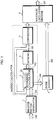
- Figure 1 is a block diagram depicting the structure of a conventional viterbi decoder, which comprises a branch metric generator 1, a calculator 2, a memory 4, a path memory 5, and a maximum likelihood decider 16.
- numeral 100 denotes a received signal, which is in effect a convolutional coded sequence transmitted from an encoder provided at a sender's end via a transmission channel.
- the convolutional coded sequence is transmitted per symbol at a time.
- R the encoding rate
- K the constraint length
- the pre-coding information sequence one symbol is represented by one bit and the encoder holds four states.
- Numeral 101 denotes a branch metric representing the likelihood of each branch.
- the branch referred herein is a line connecting the state at time (t-1) and the state at time t in the trellis diagram to indicate to which state a state has changed (in the trellis diagram, the horizontal axis represents the time when a symbol is received while the vertical axis representing the states).
- the branch metric is represented by two bits herein.
- Numeral 102 denotes a path metric representing the likelihood of a path for each state.
- the path referred herein means the history of the transition of each state, that is to say, whether each state is changed from a symbol "1" or "0".
- the path is a sequence of binary digits of "0's" and "1's” represented by a series of branches. Assume that the path metric for each state is represented by three bits herein.
- Numeral 103 denotes a path metric preceding to each path metric 102 by one time.
- Numeral 104 denotes a path signal indicating the transition of each state, that is to say, whether each state has changed by a symbol "0" or "1". Assume that the path signal for each state is represented by one bit herein.
- Numeral 105 denotes a candidate for the result of decoding for each state.
- Numeral 107 denotes a decoding result selected from the candidates in accordance with the maximum likelihood decision.
- the branch metric generator upon input of the received signal 100, calculates the branch metric 101 for each branch.
- a metric calculator comprised of the calculator 2 and memory 4, which is indicated by a dotted rectangle in the drawing, receives the branch metric 101 and outputs the path metric 103 and path signal 104.
- the calculator 2 upon input of the branch metric 101 and path metric 103, performs a metric operation for each state to calculate the path metric 102 and a new path signal 104.
- An adjuster 2a provided in the calculator 2 adjusts the value of the path metric for each state to be in a predetermined range while maintaining a correlation in terms of largeness. Because the minimum value of the path metric is always zero when there is no transmission error in the receiving signal 100, and, once the transmission error occurs, it becomes greater as the time elapses.
- the value of the path metric is adjusted to avoid an overflow, and to yield a small value for the minimum value, for example, zero, one or two for a 3-bit path metric.
- the memory 4 holds the path metric 102 from the calculator 2 and outputs the same as the path metric 103 at the following time.
- the path memory 5 receives the path signal 104, and holds a path representing the history of the symbol value for each state specified by the path signal for the latest T times, where T is an integer equal to or more than two, and outputs the oldest one bit for each state among the paths as the candidate 105.
- the maximum likelihood decider 16 receives the path metric 103 and candidate 105 for each state and checks the smallest path metric 103 to output the candidate 105 for the state corresponding to the smallest path metric as the decoding result 107.
- FIG. 2A is a block diagram depicting the structure of a circuit forming the maximum likelihood decider 16.
- the maximum likelihood decider 16 comprises a 3-bit comparator 161, a selector 162, a selector 163, a 3-bit comparator 164, a selector 165, a selector 166, a 3-bit comparator 167, and a selector 168.
- METRIC0[2:0], METRIC1[2:0], METRIC2[2:0], and METRIC3[2:0] represent the path metrics from the memory 4 in the states 0, 1, 2, and 3, respectively.
- PATH0, PATH1, PATH2, and PATH3 represent the oldest 1-bit candidates for the paths from the path memory 5 in the states 0, 1, 2, and 3, respectively.
- the comparator 161 and selector 162 compare METRIC0[2:0] with METRIC1[2:0] to select and output whichever smaller, and the resulting output is referred to as XX[2:0].
- the selector 163 selects either PATH0 or PATH1 depending on the path metric selected by the selector 162.
- the comparator 164 and selector 165 compare METRIC2[2:0] with METRIC3[2:0] to select and output whichever smaller, and the resulting output is referred to as YY[2:0].
- the selector 166 selects either PATH2 or PATH3 depending on the path metric selected by the selector 165.
- Figure 2B shows a circuit forming the comparator 161.
- the comparator 161 comprises gates 161a-161h.
- the comparators 164 and 167 are of the same structure.
- Figure 2C shows a circuit forming the selector 162.
- the selector 162 comprises three 2-input ⁇ 1-output 1-bit selectors 162a, 162b, and 162c, and each selects one of the inputs for a selection signal s.
- the received signal 100 is inputted into the branch metric generator 1 per symbol (two bits) at a time, which calculates the branch metric 101 for each branch and outputs the same to the calculator 2.
- the calculator 2 performs the metric operation for each state using the branch metric 101, and the path metric 103 from the memory 4 to calculate the path metric 102 and the new path signal 104 for each state.
- the memory 4 outputs the path metric 103 and new path signal 104 and holds the path metric 102 from the calculator 2 as a new path metric.
- the path memory 5 receives one path signal 104 at a time, and stores the value thereof for each state as the candidate while outputting the oldest one bit for each state in the paths as the candidate 105.
- the maximum likelihood decider 16 calculates the smallest path metric in all the states, and outputs the candidate for the states corresponding to the smallest path metric as the decoding result.
- the conventional viterbi decoder maximum likelihood decodes the convolutional coded sequence by performing a series of branch metric generation, metric operation, update of the path memory, and maximum likelihood decision at a time.
- the maximum likelihood decider 16 uses the circuits shown in Figures 2A, 2B, and 2C to select the smallest path metric by comparing all of the path metrics, and it is general to use a path metric of a greater number of bits to upgrade the error correction performance. Although a 3-bit metric is used for each state as an example herein, the grater the number of the bits, the larger the circuits in the maximum likelihood decider 16.
- the present invention has an object to provide a viterbi decoder comprising downsized circuits.
- a viterbi decoder for decoding a convolutional coded sequence transmitted from an encoder via a channel, wherein a plurality of paths representing a possible pre-coding data sequence and a path metric representing a likelihood of each path are calculated through a metric operation, and one of the plurality of paths is decided to be a decoding result through maximum likelihood decision based on the path metric
- the viterbi decoder comprising: a metric converting unit for, upon input of the path metric, converting a value thereof to output a conversion result as a state metric, the value being converted into k when the value is more than k, where k is a predetermined integer within a range for the path metric, and left intact when the value is equal to or less than k; and a maximum likelihood deciding unit for deciding a minimum state metric to output the decoding result using a path corresponding to the minimum state metric.
- the path metric may be represented by m bits for each path, where m is an integer, and k may be 2 m-n -1, where n is an integer in a range from one to m-1 inclusive.
- the metric converting unit may include a plurality of metric converting circuits, each being provided for the plurality of paths, respectively, each comprising m-n (n+1)-input OR gates that calculate OR's of upper n bits of a corresponding path metric and each lower bit to output (m-n)-bit state metric, whereby the maximum likelihood deciding unit decides the minimum state metric using the (m-n)-bit state metric.
- the path metric may be represented by three bits for each state; and the metric converting unit may include a plurality of metric converting circuits, each being provided for the plurality of paths, respectively, each comprising two 2-input OR gates that calculate OR's of an MSB of a corresponding path metric and each bit other than the MSB to output a 2-bit state metric, whereby the maximum likelihood deciding unit judges the minimum state metric based on the 2-bit state metric.
- the path metric can be represented by a smaller number of bits as the result of conversion, which can simplify the structure of the circuit forming the maximum likelihood decider while reducing the size thereof.
- a viterbi decoder for decoding a sequence convolutional coded by unit of an encoder holding a finite-state, comprising: a branch metric generating unit for generating a branch metric representing a likelihood of each branch based on an input code symbol in the convolutional coded sequence, one code symbol being inputted at a time, the branch representing a possible state transition in the encoder and a data symbol causing the state transition; a metric operation unit for outputting a path metric representing a likelihood of a path composed of a series of branches, and a path signal representing a value for a possibly transmitted pre-coding data symbol as a result of a metric operation using the branch metric for each state; a path memory for holding the path signal for each state for T times as a history thereof, where T is an integer equal to or more than two, and for outputting oldest path signal for each state; a metric converting unit for, upon input of the path metric for each state, converting a value
- the metric operation unit may include: a metric operation circuit for performing the metric operation for each state using a preceding path metric and the input branch metric to calculate the path metric and the path signal, the path metric being an integer equal to or more than zero and less than 2 m , where m is an integer equal to or more than one; a subtracting circuit for subtracting a minimum value among the path metrics for all the states from a value of the path metric for each state; and a memory for holding the path metric for each state received from the subtracting circuit at a time to output the same with a 1-time delay, whereby the metric converting circuit converts the 1-time delayed path metric from the memory.
- the minimum value of the pre-conversion path metric becomes always zero, which can further simplify the structure of the circuit forming the maximum likelihood decider while further reducing the size thereof.
- FIG. 3 is a block diagram depicting the structure of a viterbi decoder in accordance with an embodiment of the present invention.
- the viterbi decoder comprises a branch metric generator 1, a calculator 2, a convertor 3, a memory 4, a path memory 5, and a maximum likelihood decider 6.
- the branch metric generator 1, calculator 2, memory 4 and path memory 5 are of the same structure as their respective counterparts of the conventional viterbi decoder, and the explanation thereof is omitted.
- numerals 100-104, 105, and 107 are identical with their respective counterparts of the conventional viterbi decoder, and the explanation thereof is not repeated.
- Numeral 106 denotes a path metric, which may be referred as a state metric, converted from each path metric 103 by means of the convertor 3.
- a path metric which may be referred as a state metric, converted from each path metric 103 by means of the convertor 3.
- R the encoding rate
- K the constraint length
- the branch metric 101 is represented by two bits
- each of the path metrics 102 and 103 is represented by three bits
- the path signal for each state is represented by one bit.
- the calculator 2 is identical with its counterpart in the conventional viterbi decoder.
- the adjuster 2a that adjusts the value of the path metric is a subtracting circuit herein.
- the adjuster 2a subtracts the minimum value among the values of the path metrics for all the states from the value of the path metric in each state, and outputs the subtraction result as the path metric 102, invariably yielding zero for the minimum value.
- the convertor 3 receives the path metric 103 from the memory 4, and leaves the value thereof intact when it is equal to or less than k; otherwise, the convertor 3 converts the value into k and outputs the same to the maximum likelihood decider 6.
- the value in the path metric 103 is an integer in a range from zero to seven.
- the convertor 3 leaves the value intact when it is equal to or less than three, and converts the value into three otherwise, and outputs the value, either left intact or converted, to the maximum likelihood decider 6 as the path metric 106.
- the path metric 106 can be represented by two bits for each state.
- the maximum likelihood decider 6 upon input of the path metric 106 and candidate 105 for each state, calculates the smallest path metric 106 to output the candidate for the state corresponding to the smallest path metric 106 as the decoding result 107.
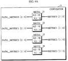
- Figure 4A is a view showing the structure of the circuit forming the convertor 3.
- the convertor 3 includes four metric converting circuits 31 through 34 for the states, 0, 1, 2, and 3, respectively.
- PATH_METRIC0[2:0], PATH_METRIC1[2:0], PATH_METRIC2[2:0], and PATH_METRIC3[2:0] denote the 3-bit path metrics from the memory 4 for the states 0, 1, 2, and 3, respectively.
- METRIC0[2:0], METRIC1[2:0], METRIC2[2:0], and METRIC3[2:0] denote the post-conversion 2-bit path metric for the states 0, 1, 2, and 3, respectively.
- the metric converting circuit 31 receives PATH_METRIC0[2:0], which varies in a range from zero to seven, and when PATH_METRIC0[2:0] is more than three, it converts the same into three to output 2-bit METRIC0[1:0].
- Figure 4B shows a circuit forming the metric converting circuit 31 more in detail.
- the metric converting circuit 31 comprises OR gates 31a and 31b.
- the metric converting circuits 32 through 34 are of the same structure as the metric converting circuits 31.
- the path metric is converted into the one in a shorter bit length by means of the convertor 3.
- the levels of the value of the path metric is reduced to four from eight.
- converting the value of the path metric does not affect the maximum likelihood decision. Because although eight levels are conventionally used to find the path metric with the minimum value, it is well known from the experiences that the minimum value of the path metric becomes zero, one, two, or three in most of the cases due to the adjuster 2a. Since the subtraction circuit serves as the adjuster 2a herein, the minimum value becomes always zero.
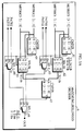
- Figure 5A is a block diagram depicting the structure of a circuit forming the maximum likelihood decider 6.
- the maximum likelihood decider 6 comprises a 2-bit comparator 61, a selector 62, a selector 63, a 2-bit comparator 64, a selector 65, a selector 66 a 2-bit comparator 67, and a selector 68.
- METRIC0[1:0], METRIC1[1:0], METRIC2[1:0], METRIC3[1:0] represent the post-conversion path metrics from the convertor 3 for the states 0, 1, 2 and 3, respectively.
- PATH0, PATH1, PATH2, and PATH3 represent the oldest 1-bit candidates from the path memory 5 for the states 0, 1, 2, and 3, respectively.
- the comparator 61 and selector 62 compares METRIC0[1:0] with METRIC1[1:0] to select and output whichever smaller, and the resulting output is referred to as X[1:0].
- the selector 63 selects either PATH0 or PATH1 depending on the path metric selected by the selector 62.
- the comparator 64 and selector 65 compares METRIC2[1:0] with METRIC3[1:0] to select and output whichever smaller, and the resulting output is referred to as Y[1:0].
- the selector 66 selects and outputs either PATH2 or PATH3 depending on the path metric selected by the selector 65.
- Figure 5B is a view showing a circuit forming the comparator 61.
- the comparator 61 comprises gates 61a through 61d.
- the comparators 64 and 67 operate in the same manner.
- Figure 5C is a view showing a circuit forming the selector 62.
- the selector 62 comprises two 2-input ⁇ 1-output 1-bit selectors 62a and 62b, and each selects one of the inputs (D0 and D1) depending on a selection signal s.
- the operation of the above viterbi decoder will be explained in the following.
- the branch metric generator 1, calculator 2, memory unit 4, and path memory 5 operate in the same manner as their respective counterparts of the conventional viterbi decoder, and the explanation is not repeated.
- the convertor 3 receives the 3-bit path metrics from the memory 4 (PATH_METRIC0[2:0], PATH_METRIC1[2:0], PATH_METRIC2[2:0], and PATH_METRIC3[2:0] in Figure 4A) for each of the states 0, 1, 2 and 3. Although the value in each path metric varies in a range from zero to seven, the convertor 3 converts the value into three if it is more than three, and leaves the same intact when it is equal to or less than three, converting the 3-bit path metrics into the 2-bit path metrics (METRIC0[2:0], METRIC1[2:0], METRIC2[2:0], and METRIC3[2:0] in Figure 4A).
- the path metric for each state thus converted is entered into the maximum likelihood decider 6, which calculates the smallest path metric and outputs the candidate for the state corresponding to the smallest path metric as the decoding result.
- the viterbi decoder of the present invention converts the path metric into the one in a shorter bit length.
- the maximum likelihood decider 6 can be comprised of a downsized circuit compared with the conventional maximum likelihood decider 16. Although eight OR gates in the convertor 3 are additionally included, such an increase is offset by downsizing of the maximum likelihood circuit 6, enabling a viterbi decoder comprising downsized circuits.
- the maximum likelihood circuit 6 is realized in the form of hardware herein, but the amount of processing can be reduced as well when it is realized in the form of a software program once the convertor 3 is provided.
- each path metric can be represented by one bit, further downsizing the maximum likelihood decider 6.
- each metric converting circuit in the convertor 3 may comprise m-n (n+1)-input OR gates that calculate the OR's of the upper n (n is greater than one and less than m-1 inclusive) bits of the corresponding path metric and each lower bit.
Landscapes
- Physics & Mathematics (AREA)
- Probability & Statistics with Applications (AREA)
- Engineering & Computer Science (AREA)
- Theoretical Computer Science (AREA)
- Error Detection And Correction (AREA)
- Dc Digital Transmission (AREA)
Applications Claiming Priority (2)
| Application Number | Priority Date | Filing Date | Title |
|---|---|---|---|
| JP53944/94 | 1994-03-24 | ||
| JP05394494A JP3203941B2 (ja) | 1994-03-24 | 1994-03-24 | ビタビ復号装置 |
Publications (2)
| Publication Number | Publication Date |
|---|---|
| EP0674397A2 true EP0674397A2 (fr) | 1995-09-27 |
| EP0674397A3 EP0674397A3 (fr) | 1996-07-31 |
Family
ID=12956845
Family Applications (1)
| Application Number | Title | Priority Date | Filing Date |
|---|---|---|---|
| EP95301939A Withdrawn EP0674397A3 (fr) | 1994-03-24 | 1995-03-23 | Décodeur Viterbi comprenant des circuits de taille réduite. |
Country Status (3)
| Country | Link |
|---|---|
| EP (1) | EP0674397A3 (fr) |
| JP (1) | JP3203941B2 (fr) |
| CA (1) | CA2145228A1 (fr) |
Cited By (2)
| Publication number | Priority date | Publication date | Assignee | Title |
|---|---|---|---|---|
| WO1997021275A1 (fr) * | 1995-12-04 | 1997-06-12 | Nokia Telecommunications Oy | Procede d'etablissement de parametres de transition et recepteur de systeme radio cellulaire |
| CN113824452A (zh) * | 2021-11-23 | 2021-12-21 | 南京创芯慧联技术有限公司 | 基于网格图的译码方法、分量译码器和信道译码器 |
Families Citing this family (1)
| Publication number | Priority date | Publication date | Assignee | Title |
|---|---|---|---|---|
| KR100338388B1 (ko) * | 1995-12-28 | 2002-10-31 | 사단법인 고등기술연구원 연구조합 | 경판정방식을이용한비터기복호기 |
Citations (5)
| Publication number | Priority date | Publication date | Assignee | Title |
|---|---|---|---|---|
| EP0233788A2 (fr) * | 1986-02-19 | 1987-08-26 | Sony Corporation | Décodeur Viterbi et méthode |
| EP0409205A2 (fr) * | 1989-07-18 | 1991-01-23 | Sony Corporation | Décodeur de viterbi |
| EP0467522A2 (fr) * | 1990-07-19 | 1992-01-22 | Nokia Mobile Phones (U.K.) Limited | Détecteur de séquence à maximum de vraisemblance |
| EP0529909A2 (fr) * | 1991-08-23 | 1993-03-03 | Matsushita Electric Industrial Co., Ltd. | Méthode et appareil de codage/décodage de correction d'erreur |
| FR2681486A1 (fr) * | 1991-09-13 | 1993-03-19 | Sony Corp | Appareil de decodage de viterbi. |
-
1994
- 1994-03-24 JP JP05394494A patent/JP3203941B2/ja not_active Expired - Fee Related
-
1995
- 1995-03-22 CA CA 2145228 patent/CA2145228A1/fr not_active Abandoned
- 1995-03-23 EP EP95301939A patent/EP0674397A3/fr not_active Withdrawn
Patent Citations (5)
| Publication number | Priority date | Publication date | Assignee | Title |
|---|---|---|---|---|
| EP0233788A2 (fr) * | 1986-02-19 | 1987-08-26 | Sony Corporation | Décodeur Viterbi et méthode |
| EP0409205A2 (fr) * | 1989-07-18 | 1991-01-23 | Sony Corporation | Décodeur de viterbi |
| EP0467522A2 (fr) * | 1990-07-19 | 1992-01-22 | Nokia Mobile Phones (U.K.) Limited | Détecteur de séquence à maximum de vraisemblance |
| EP0529909A2 (fr) * | 1991-08-23 | 1993-03-03 | Matsushita Electric Industrial Co., Ltd. | Méthode et appareil de codage/décodage de correction d'erreur |
| FR2681486A1 (fr) * | 1991-09-13 | 1993-03-19 | Sony Corp | Appareil de decodage de viterbi. |
Cited By (4)
| Publication number | Priority date | Publication date | Assignee | Title |
|---|---|---|---|---|
| WO1997021275A1 (fr) * | 1995-12-04 | 1997-06-12 | Nokia Telecommunications Oy | Procede d'etablissement de parametres de transition et recepteur de systeme radio cellulaire |
| US6009127A (en) * | 1995-12-04 | 1999-12-28 | Nokia Telecommunications Oy | Method for forming transition metrics and a receiver of a cellular radio system |
| AU717161B2 (en) * | 1995-12-04 | 2000-03-16 | Nokia Telecommunications Oy | Method for forming transition metrics and a receiver of a cellular radio system |
| CN113824452A (zh) * | 2021-11-23 | 2021-12-21 | 南京创芯慧联技术有限公司 | 基于网格图的译码方法、分量译码器和信道译码器 |
Also Published As
| Publication number | Publication date |
|---|---|
| JP3203941B2 (ja) | 2001-09-04 |
| JPH07264080A (ja) | 1995-10-13 |
| EP0674397A3 (fr) | 1996-07-31 |
| CA2145228A1 (fr) | 1995-09-25 |
Similar Documents
| Publication | Publication Date | Title |
|---|---|---|
| US5471500A (en) | Soft symbol decoding | |
| US5349608A (en) | Viterbi ACS unit with renormalization | |
| EP1397869B1 (fr) | Procede de decodage d'une sequence de mots codes de longueur variable | |
| US4500994A (en) | Multi-rate branch metric processor for maximum-likelihood convolutional decoder | |
| KR100276780B1 (ko) | 신호 전송 시스템 | |
| KR20090009892A (ko) | 라딕스-4 비터비 디코딩 | |
| EP0945989A1 (fr) | Décodage Viterbi | |
| JPH10117149A (ja) | ビタービ復号化器用トレースバック装置及びトレースバック方法 | |
| JPH0316046B2 (fr) | ||
| GB2315001A (en) | Viterbi decoder for depunctured codes | |
| US5450338A (en) | Add-compare-select device | |
| US6792570B2 (en) | Viterbi decoder with high speed processing function | |
| US7046747B2 (en) | Viterbi decoder and decoding method using rescaled branch metrics in add-compare-select operations | |
| KR100387089B1 (ko) | 브랜치 메트릭 계산 처리에서 감소된 비트수를 갖는비터비 디코더 | |
| EP0674397A2 (fr) | Décodeur Viterbi comprenant des circuits de taille réduite | |
| US7062000B1 (en) | Viterbi decoder | |
| US20040064781A1 (en) | Viterbi decoder and Viterbi decoding method | |
| EP0807336B1 (fr) | Procede d'etablissement de parametres de transition et recepteur de systeme radio cellulaire | |
| KR101134806B1 (ko) | 부호 복호 방법 | |
| AU2000229439B2 (en) | Viterbi decoder | |
| KR100531840B1 (ko) | 비터비 디코더의 가지 메트릭 계산 방법 및 그 회로 | |
| KR0180303B1 (ko) | 비터비 디코더의 정규화 방법 및 장치 | |
| KR100333336B1 (ko) | 비터비 복호기의 역추적 방법 | |
| US20040153958A1 (en) | Path metric calculation circuit in viterbi decoders | |
| JPH0677845A (ja) | 畳み込み符号化およびビタビ復号化方式 |
Legal Events
| Date | Code | Title | Description |
|---|---|---|---|
| PUAI | Public reference made under article 153(3) epc to a published international application that has entered the european phase |
Free format text: ORIGINAL CODE: 0009012 |
|
| AK | Designated contracting states |
Kind code of ref document: A2 Designated state(s): DE FR GB |
|
| PUAL | Search report despatched |
Free format text: ORIGINAL CODE: 0009013 |
|
| AK | Designated contracting states |
Kind code of ref document: A3 Designated state(s): DE FR GB |
|
| STAA | Information on the status of an ep patent application or granted ep patent |
Free format text: STATUS: THE APPLICATION IS DEEMED TO BE WITHDRAWN |
|
| 18D | Application deemed to be withdrawn |
Effective date: 19970201 |