EP0674058B1 - Panel fixture for façade, roof, window or door - Google Patents
Panel fixture for façade, roof, window or door Download PDFInfo
- Publication number
- EP0674058B1 EP0674058B1 EP95810194A EP95810194A EP0674058B1 EP 0674058 B1 EP0674058 B1 EP 0674058B1 EP 95810194 A EP95810194 A EP 95810194A EP 95810194 A EP95810194 A EP 95810194A EP 0674058 B1 EP0674058 B1 EP 0674058B1
- Authority
- EP
- European Patent Office
- Prior art keywords
- profile bar
- roof
- profile bars
- bars
- roof profile
- Prior art date
- Legal status (The legal status is an assumption and is not a legal conclusion. Google has not performed a legal analysis and makes no representation as to the accuracy of the status listed.)
- Expired - Lifetime
Links
Images


Classifications
-
- E—FIXED CONSTRUCTIONS
- E04—BUILDING
- E04B—GENERAL BUILDING CONSTRUCTIONS; WALLS, e.g. PARTITIONS; ROOFS; FLOORS; CEILINGS; INSULATION OR OTHER PROTECTION OF BUILDINGS
- E04B2/00—Walls, e.g. partitions, for buildings; Wall construction with regard to insulation; Connections specially adapted to walls
- E04B2/88—Curtain walls
- E04B2/96—Curtain walls comprising panels attached to the structure through mullions or transoms
- E04B2/965—Connections of mullions and transoms
-
- E—FIXED CONSTRUCTIONS
- E04—BUILDING
- E04D—ROOF COVERINGS; SKY-LIGHTS; GUTTERS; ROOF-WORKING TOOLS
- E04D3/00—Roof covering by making use of flat or curved slabs or stiff sheets
- E04D3/02—Roof covering by making use of flat or curved slabs or stiff sheets of plane slabs, slates, or sheets, or in which the cross-section is unimportant
- E04D3/06—Roof covering by making use of flat or curved slabs or stiff sheets of plane slabs, slates, or sheets, or in which the cross-section is unimportant of glass or other translucent material; Fixing means therefor
- E04D3/14—Roof covering by making use of flat or curved slabs or stiff sheets of plane slabs, slates, or sheets, or in which the cross-section is unimportant of glass or other translucent material; Fixing means therefor with glazing bars of other material, e.g. of glass
-
- E—FIXED CONSTRUCTIONS
- E06—DOORS, WINDOWS, SHUTTERS, OR ROLLER BLINDS IN GENERAL; LADDERS
- E06B—FIXED OR MOVABLE CLOSURES FOR OPENINGS IN BUILDINGS, VEHICLES, FENCES OR LIKE ENCLOSURES IN GENERAL, e.g. DOORS, WINDOWS, BLINDS, GATES
- E06B3/00—Window sashes, door leaves, or like elements for closing wall or like openings; Layout of fixed or moving closures, e.g. windows in wall or like openings; Features of rigidly-mounted outer frames relating to the mounting of wing frames
- E06B3/30—Coverings, e.g. protecting against weather, for decorative purposes
- E06B3/301—Coverings, e.g. protecting against weather, for decorative purposes consisting of prefabricated profiled members or glass
- E06B3/302—Covering wooden frames with metal or plastic profiled members
-
- E—FIXED CONSTRUCTIONS
- E06—DOORS, WINDOWS, SHUTTERS, OR ROLLER BLINDS IN GENERAL; LADDERS
- E06B—FIXED OR MOVABLE CLOSURES FOR OPENINGS IN BUILDINGS, VEHICLES, FENCES OR LIKE ENCLOSURES IN GENERAL, e.g. DOORS, WINDOWS, BLINDS, GATES
- E06B3/00—Window sashes, door leaves, or like elements for closing wall or like openings; Layout of fixed or moving closures, e.g. windows in wall or like openings; Features of rigidly-mounted outer frames relating to the mounting of wing frames
- E06B3/96—Corner joints or edge joints for windows, doors, or the like frames or wings
- E06B3/99—Corner joints or edge joints for windows, doors, or the like frames or wings for continuous frame members crossing each other with out interruption
-
- E—FIXED CONSTRUCTIONS
- E04—BUILDING
- E04D—ROOF COVERINGS; SKY-LIGHTS; GUTTERS; ROOF-WORKING TOOLS
- E04D3/00—Roof covering by making use of flat or curved slabs or stiff sheets
- E04D3/02—Roof covering by making use of flat or curved slabs or stiff sheets of plane slabs, slates, or sheets, or in which the cross-section is unimportant
- E04D3/06—Roof covering by making use of flat or curved slabs or stiff sheets of plane slabs, slates, or sheets, or in which the cross-section is unimportant of glass or other translucent material; Fixing means therefor
- E04D3/08—Roof covering by making use of flat or curved slabs or stiff sheets of plane slabs, slates, or sheets, or in which the cross-section is unimportant of glass or other translucent material; Fixing means therefor with metal glazing bars
- E04D2003/0843—Clamping of the sheets or glass panes to the glazing bars by means of covering strips
- E04D2003/0856—Clamping of the sheets or glass panes to the glazing bars by means of covering strips locked by screws, bolts or pins
-
- E—FIXED CONSTRUCTIONS
- E04—BUILDING
- E04D—ROOF COVERINGS; SKY-LIGHTS; GUTTERS; ROOF-WORKING TOOLS
- E04D3/00—Roof covering by making use of flat or curved slabs or stiff sheets
- E04D3/02—Roof covering by making use of flat or curved slabs or stiff sheets of plane slabs, slates, or sheets, or in which the cross-section is unimportant
- E04D3/06—Roof covering by making use of flat or curved slabs or stiff sheets of plane slabs, slates, or sheets, or in which the cross-section is unimportant of glass or other translucent material; Fixing means therefor
- E04D3/08—Roof covering by making use of flat or curved slabs or stiff sheets of plane slabs, slates, or sheets, or in which the cross-section is unimportant of glass or other translucent material; Fixing means therefor with metal glazing bars
- E04D2003/0868—Mutual connections and details of glazing bars
Definitions
- the invention relates to a plate holder according to the Preamble of claim 1, a plate holder for a facade, a roof, a window or a door.
- a plate holder is known for example from EP-A-0 369 326.
- a profile bar construction provide at least two to each other parallel, vertical, first profile bars as posts one Skeletons of a facade, which, together with them, second profile bars several arranged one above the other Limit fields that are used, for example, as windows, clear glass plates or alternately serving as windows Glass plates and opaque, plate-shaped facade elements contain.
- the invention now preferably relates to a metal one Deck profile bars composite plate bracket that has a wooden frame formed from supporting profile bars.
- the cover profile bars are preferably made of weatherproof, emoloxized or color coated Aluminum, copper or brass.
- plastic holding elements for example glass fiber reinforced polyamide formed holding elements used, which are screwed onto the supporting profile bars. On these holding elements are then clipped onto the cover profile bars or snapped into place.
- the Holding elements any elastic or rotatable tongues or have feet that have corresponding ribs, for example the free ends of a C-profile open against the holding elements, the support profile bars can reach behind.
- Such Holding elements are attached to the wood about every 10 to 50 cm, thus ensuring a secure hold of the deck profile bars is. It goes without saying that such use Holding elements must be attached exactly in a line must, since otherwise there is no deck profile bar at all can be clipped on.
- the invention is based on the object, one of several To create profile bars that can be put together, that does not have the aforementioned disadvantages.
- This task is carried out by a support and deck profile bars Composable plate holder with the characteristics of the Claim 1 solved.
- the shown in Figures 1 and 3 and as a whole 1 designated plate holder for a multi-window Facade has one of several supporting profile bars 2 formed, cross-shaped carrier 3, on which four pairs of glass plates 4 rest.
- a first and two second cover profile bars 5 and 6 are on the support bars 2 a first and two second cover profile bars 5 and 6 releasable attached, the glass plate pairs 4 on the carrier 3rd clamp.
- the two second deck profile bars meet 6 at two opposing joints of the Flanges 5a of the first cover profile rod 5 on this.
- the Deck profile bars 5 and 6 an open to the carrier 3, angular C-profile on that through the front bar 5b or 6b and the two flanges 5a and 6a is formed.
- the deck profile bars 5 and 6 now also have two each between the two Flanges 5a and 6a arranged legs 5c and 6c, which the space between the flanges 5a and 6a into one middle channel 5d or 6d and two outer channels 5e or 6e divided.
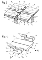
- a sealing element 9 is arranged. This is shown in Figure 4 and in the Figures 5 and 6 together with the cover profile bar 5 and 6 respectively shown and preferably consists of a one-piece Plastic body, which is preferably completely through Injection molding has been made.
- a material for manufacturing of the sealing element 9 are particularly suitable here synthetic rubbers, such as EPDM (ethylene propylene diene monomer).
- the sealing element 9 is substantially cross-shaped and has a U-shaped first sealing part 10 and one this second sealing part 11 forming a right angle on.
- the first sealing part 10 now has two on it the second sealing part 11 projecting end portions each two cams 12 which are dimensioned and arranged in such a way that - as shown in Figure 5 - during manufacture the plate holder in the outer grooves 6e of the two at the abutting point on the first cover profile bar 5, second sealing profile bars 6 engage.
- the cams 12 additionally with at least a circumferential rib 12a may be provided, which in attached The interior walls fit more or less well of the outer channels 6e.
- the sealing element 9 sits on one another to the right Angle-forming support profile bars 2 and is at least a support profile rod 2 fastened with two screws 13.
- this is now so placed on the support profile bars 2 that the each other a right angle forming profile bars 2 with a Part between at least two, arranged parallel to each other Guide ribs 14 come to rest.
- the two gasket parts 10 and 11 at their mutually projecting edge sections provided with a bevel 10a or 11b such that the L-shaped sealing strips when manufacturing the plate holder fit into these bevels 10a and 11b and thereby in the attached state with the sealing element 9 work together in a sealing manner.
- Figure 3 also shows the support profile bars 2 arranged holding elements 15. These serve the deck profile bars 5 and 6 to be fastened to the supporting profile bars 2. They engage you with a wrench bringable screw part 16 and a in the middle groove 5d or 6d of a deck profile rod 5 or 6 determined to sit Foot 17 on.
- the latter is designed and dimensioned in such a way that it is in an insertion position of the open long side of the central channel 5d or 6d one in this existing narrowing into an extension insertable and then by turning the screw part 16 in his stop position can be brought in which he engages behind the constriction.
- FIG. 7 shows three supporting profile bars 2 fasteners belonging to them. These show one each on the outside of a first support profile bar 2 attached plate 18 and one at the end of a second support profile bar 2 sunk, for receiving the plate 18 T-slide connector 19 on.
- the support profile bar 2 with the T-slide connector 19 can be used in the manufacture of a Window frames from the inside on the first support profile bar 2 attached plate 18 can be pushed. To secure This attachment can still be done from the outside additionally a metallic pin between the plate 18 and the T-slide connector 19 are inserted, these spread apart and thereby the profile rod connection is secured.
Landscapes
- Engineering & Computer Science (AREA)
- Civil Engineering (AREA)
- Structural Engineering (AREA)
- Architecture (AREA)
- Physics & Mathematics (AREA)
- Electromagnetism (AREA)
- Securing Of Glass Panes Or The Like (AREA)
- Window Of Vehicle (AREA)
- Wing Frames And Configurations (AREA)
- Roof Covering Using Slabs Or Stiff Sheets (AREA)
Abstract
Description
Die Erfindung betrifft eine Plattenhalterung gemäss dem
Oberbegriff des Anspruchs 1, eine Plattenhalterung für
eine Fassade, ein Dach, ein Fenster oder eine Tür.
Eine solche Plattenhalterung
ist beispielsweise durch EP-A-0 369 326 bekannt.The invention relates to a plate holder according to the
Preamble of
Es sind verschiedenartige Konstruktionen von Plattenhalterungen möglich. So kann man beispielsweise eine Profilstabkonstruktion vorsehen, bei der mindestens zwei zueinander parallele, vertikale, erste Profilstäbe als Pfosten eines Gerippes einer Fassade dienen, die zusammen mit sie verbindenden, zweiten Profilstäben mehrere übereinander angeordnete Felder begrenzen, die beispielsweise als Fenster dienende, durchsichtige Glasplatten oder abwechselnd als Fenster dienende Glasplatten und undurchsichtige, plattenförmige Fassadenelemente enthalten.They are different types of plate holders possible. So you can, for example, a profile bar construction provide at least two to each other parallel, vertical, first profile bars as posts one Skeletons of a facade, which, together with them, second profile bars several arranged one above the other Limit fields that are used, for example, as windows, clear glass plates or alternately serving as windows Glass plates and opaque, plate-shaped facade elements contain.
Die Erfindung betrifft nun vorzugsweise eine aus metallenen Deck-Profilstäben zusammengesetzte Plattenhalterung, die einen aus Trag-Profilstäben gebildeten Holzrahmen aufweist. Hierbei bestehen die Deck-Profilstäbe vorzugsweise aus witterungsbeständigem, emoloxiertem oder farbbeschichtetem Aluminium, Kupfer oder Messing.The invention now preferably relates to a metal one Deck profile bars composite plate bracket that has a wooden frame formed from supporting profile bars. Here, the cover profile bars are preferably made of weatherproof, emoloxized or color coated Aluminum, copper or brass.
Bei Holz-Metallfenstern stellt sich stets das Problem, wie man die metallenen Deck-Profilstäbe an den Trag-Profilstäben befestigen und wie man die von den Profilstäben gehaltenen Glasplatten fluiddichte abdichten kann.With wood-metal windows, the problem always arises how the metal deck profile bars on the support profile bars attach and how to hold those held by the profile bars Glass plates can seal fluid-tight.
Zur Befestigung der Deck-Profilstäbe auf dem Holzrahmen werden sehr oft Kunststoff-Halteelemente, beispielsweise aus glasfaserverstärktem Polyamid gebildete Halteelemente, verwendet, die auf die Trag-Profilstäbe aufgeschraubt werden. Auf diese Halteelemente werden dann die Deck-Profilstäbe aufgeklipst oder eingerastet. Dazu ist es natürlich nötig, dass die Halteelemente irgendwelche elastische oder drehbare Zungen oder Füsse aufweisen, die entsprechende Rippen, beispielsweise die freien Enden eines gegen die Halteelemente offenen C-Profiles, der Trag-Profilstäbe hintergreifen können. Derartige Halteelemente werden ca. alle 10 bis 50 cm auf dem Holz befestigt, damit ein sicherer Halt der Deck-Profilstäbe gewährleistet ist. Es versteht sich von selbst, dass derart zu verwendende Halteelemente genau in einer Linie befestigt sein müssen, da sich ja andernfalls ein Deck-Profilstab gar nicht aufklipsen lässt.For fastening the deck profile bars to the wooden frame are very often plastic holding elements, for example glass fiber reinforced polyamide formed holding elements used, which are screwed onto the supporting profile bars. On these holding elements are then clipped onto the cover profile bars or snapped into place. For this it is of course necessary that the Holding elements any elastic or rotatable tongues or have feet that have corresponding ribs, for example the free ends of a C-profile open against the holding elements, the support profile bars can reach behind. Such Holding elements are attached to the wood about every 10 to 50 cm, thus ensuring a secure hold of the deck profile bars is. It goes without saying that such use Holding elements must be attached exactly in a line must, since otherwise there is no deck profile bar at all can be clipped on.
Zum Abdichten des Fensters wird bei der Verwendung von bekannten Plattenhalterungen eine Verglasungsdichtung zwischen die Deck-Profilstäbe und die Glasränder sowie auch zwischen aneinander anstossende erste und zweite Deck-Profilstäbe angeordnet. Diese Verglasungsdichtung wird dabei vorzugsweise mittels eines aus Kunststoff gebildeten Dichtungskittes hergestellt.To seal the window is known when using known Panel mounts a glazing gasket between the deck profile bars and the glass edges as well as between abutting first and second cover profile bars arranged. This glazing gasket is preferred produced by means of a sealing putty made of plastic.
Derart hergestellte Plattenhalterungen weisen nun den Nachteil auf, dass die Herstellung der Verglasungsdichtung sehr umständlich, zeitraubend und daher verhältnismässig teuer ist. Zudem haben die mittels des Kittes gebildeten, insbesondere die zwischen den aneinander anstossenden Profilstäben eingefügten, Dichtungen den weiteren Nachteil, dass sie aufgrund von an den Fenstergläser bzw. an den metallenen Deck-Profilstäben oft herrschenden hohen Aussentemperaturen, die ohne weiteres 40°C betragen können, sehr starken Längenveränderungen der Plattenhalterung unterworfen sind, was schliesslich einen ungünstigen Einfluss auf die Beständigkeit und Konsistenz der Dichtung zur Folge.Plate holders manufactured in this way now have the Disadvantage that the manufacture of the glazing gasket very cumbersome, time consuming and therefore relatively expensive is. In addition, those formed by means of the putty, in particular between the abutting profile bars inserted, seals have the further disadvantage that they are due from on the window glasses or on the metal cover profile bars often prevailing high outside temperatures that can easily be 40 ° C, very large changes in length are subject to the plate holder, which is ultimately an unfavorable influence on the durability and consistency the seal.
Der Erfindung liegt nun die Aufgabe zugrunde, eine aus mehreren Profilstäben zusammensetzbare Plattenhalterung zu schaffen, die die vorgenannten Nachteile nicht aufweist.The invention is based on the object, one of several To create profile bars that can be put together, that does not have the aforementioned disadvantages.
Diese Aufgabe wird durch eine aus Trag- und Deck-Profilstäben
zusammensetzbare Plattenhalterung mit den Merkmalen des
Patentanspruches 1 gelöst.This task is carried out by a support and deck profile bars
Composable plate holder with the characteristics of the
Vorteilhafte Ausgestaltungen der Erfindung gehen aus den abhängigen Ansprüchen hervor.Advantageous embodiments of the invention are shown in the dependent claims.
Der Erfindungsgegenstand wird nun anhand eines in der
Zeichnung dargestellten Ausführungsbeispieles erläutert. In
der Zeichnung zeigen
Die in den Figuren 1 und 3 dargestellte und als ganzes mit
1 bezeichnete Plattenhalterung für eine mehrere Fenster aufweisende
Fassade besitzt einen aus mehreren Trag-Profilstäben
2 gebildeten, kreuzförmigen Träger 3, auf welchem vier Glasplattenpaare
4 aufliegen. Auf den Trag-Profilstäben 2 sind dabei
ein erstes und zwei zweite Deck-Profilstäbe 5 bzw. 6 lösbar
befestigt, die die Glasplattenpaare 4 auf dem Träger 3
festklemmen. Hierbei stossen die beiden zweiten Deck-Profilstäbe
6 bei zwei einander gegenüberliegenden Stoss-Stellen der
Flansche 5a des ersten Deck-Profilstabes 5 an diesen an.The shown in Figures 1 and 3 and as a whole
1 designated plate holder for a multi-window
Facade has one of several supporting
Wie aus der Figur 1 zudem ersichtlich ist, befindet sich
zwischen den Glasplattenpaaren 4 und den Trag-Profilstäben 2
noch zusätzlich ein Dichtungsband 7 sowie ein in der Zeichnung
nicht dargestelltes, der Hinterlüftung dienendes Verglasungselement.
Ferner klemmen die Deck-Profilstäbe 5 und 6 in Befestigtem
Zustand mit ihren Flanschen 5a bzw. 6a je zwei an
den nach aussen gerichteten Rändern der Glasplattenpaare 4
aufliegende, L-förmige Dichtungsleisten 8 fest.As can also be seen from FIG
between the pairs of
Wie man speziell aus der Figur 2 ersehen kann, weisen die
Deck-Profilstäbe 5 und 6 ein zum Träger 3 hin offenes, eckiges
C-Profil auf, das durch die Frontleiste 5b bzw. 6b sowie die
beiden Flansche 5a bzw. 6a gebildet wird. Die Deck-Profilstäbe
5 und 6 besitzen nun zusätzlich je zwei zwischen den beiden
Flanschen 5a bzw. 6a angeordnete Schenkel 5c bzw. 6c, welche
den zwischen den Flanschen 5a bzw. 6a vorhandene Raum in eine
mittlere Rinne 5d bzw. 6d und zwei äussere Rinnen 5e bzw. 6e
unterteilt.As can be seen specifically from FIG. 2, the
Bei jeder Stoss-Stelle des ersten Deck-Profilstabes 5 ist
- wie in der Figur 3 dargestellt - ein Dichtungselement 9 angeordnet.
Dieses ist in der Figur 4 in Ansicht und in den
Figuren 5 und 6 zusammen mit dem Deck-Profilstab 5 bzw. 6
dargestellt und besteht vorzugsweise aus einem einstückigen
Körper aus Kunststoff, der vorzugsweise vollständig durch
Spritzgiessen hergestellt worden ist. Als Material zur Herstellung
des Dichtungselementes 9 eignen sich hierbei insbesondere
synthetische Kautschuke, wie etwa EPDM (Ethylen-Propylen-Dien-Monomer).There is 5 at every butt joint of the first cover profile bar
- As shown in Figure 3 - a
Das Dichtungselement 9 ist im wesentlichen kreuzförmig und
weist einen U-förmigen ersten Dichtungsteil 10 und einen mit
diesem einen rechten Winkel bildenden zweiten Dichtungsteil 11
auf. Das erste Dichtungsteil 10 besitzt nun an seinen beiden
den zweiten Dichtungsteil 11 überstehenden Endabschnitten je
zwei Nocken 12, die derart dimensioniert und angeordnet sind,
dass sie - wie in der Figur 5 dargestellt - bei der Herstellung
der Plattenhalterung in die äusseren Rinnen 6e der beiden
bei der Stoss-Stelle an den ersten Deck-Profilstab 5 anstossenden,
zweiten Deck-Profilstäbe 6 dichtend eingreifen. Hierzu
können die Nocken 12 beispielsweise noch zusätzlich mit mindestens
einer umlaufenden Rippe 12a versehen sein, die in befestigtem
Zustand mehr oder weniger satt passend die Innenwände
der äusseren Rinnen 6e berühren. Demgegenüber greift das
zweite Dichtungsteil 11 mit seiner ganzen Oberseite 11a
zwischen die beiden Flansche 5a des ersten Deck-Profilstabes 5
ein, wobei die durch die Flansche 5a gebildete lichte Tiefe
des C-Profiles vorzugsweise etwas grösser ist als die durch
die beiden Schenkel 5c gebildete Tiefe der mittleren Rinne 5d.
Hierzu sei noch abschliessend erwähnt, dass die in der Figur 5
dargestellte Verbindung eines zweiten Profilstabes 6 mit dem
Dichtungselement 9 noch einen weiteren, in der Figur 2 ebenfalls
dargestellten, Dichtungskörper 20 besitzt, der in Befestigtem
Zustand mehr oder weniger satt passend in der mittleren
Rinne 6d sitzt.The sealing
Wie aus den Figuren 3, 5 und 6 zudem ersichtlich ist,
sitzt das Dichtungselement 9 auf miteinander einen rechten
Winkel bildenden Trag-Profilstäben 2 und ist dabei auf mindestens
einem Trag-Profilstab 2 mit zwei Schrauben 13 befestigt.
Bei der Befestigung des Dichtungseiementes 9 wird dieses nun
derart auf die Trag-Profilstäbe 2 gesetzt, dass die miteinander
einen rechten Winkel bildenden Profilstäbe 2 mit einem
Teil zwischen jeweils mindestens zwei, zueinander parallel angeordnete
Führungsrippen 14 zu liegen kommen. Wie aus diesen
Figuren ebenfalls ersichtlich ist, sind die beiden Dichtung.steile
10 und 11 an ihren einander überstehenden Randabschnitten
derart mit einer Anschrägung 10a bzw. 11b versehen, dass
bei der Herstellung der Plattenhalterung die L-förmigen Dichtungsleisten
in diese Anschrägungen 10a und 11b passen und dadurch
in Befestigtem Zustand mit dem Dichtungselement 9
dichtend zusammenwirken.As can also be seen from FIGS. 3, 5 and 6,
the sealing
Die Figur 3 zeigt noch zusätzlich an den Trag-Profilstäben
2 angeordnete Halteelemente 15. Diese dienen dazu, die Deck-Profilstäbe
5 und 6 auf den Trag-Profilstäben 2 zu befestigen.
Sie weisen einen mit einem Schraubenschlüssel in Eingriff
bringbaren Schraubteil 16 sowie einen in die mittlere Rinne 5d
bzw. 6d eines Deck-Profilstabes 5 bzw. 6 zu sitzen bestimmten
Fuss 17 auf. Letzterer ist dabei derart ausgebildet und dimensioniert,
dass er bei der Montage in einer Einführstellung von
der offenen Längsseite der mittlere Rinne 5d bzw. 6d her durch
eine in dieser vorhandenen Verengung hindurch in eine Erweiterung
einführbar und dann durch Drehen des Schraubteiles 16 in
seine Haltestellung bringbar ist, in der er die Verengung hintergreift.Figure 3 also shows the
Die Figur 7 zeigt schliesslich drei Trag-Profilstäbe 2 mit
zu ihnen gehörenden Befestigungsmitteln. Diese weisen dabei
je eine an der Aussenseite eines ersten Trag-Profilstabes 2
befestigte Platte 18 und einen am Ende eines zweiten Trag-Profilstabes
2 versenkten, zur Aufnahme der Platte 18 dienenden
T-Schiebeverbinder 19 auf. Der Trag-Profilstab 2 mit
dem T-Schiebeverbinder 19 kann bei der Herstellung eines
Fenstergerippes von innen auf die an dem ersten Trag-Profilstab
2 befestigte Platte 18 aufgeschoben werden. Zur Sicherung
dieser Befestigung kann nachträglich von aussen noch
zusätzlich ein metallischer Stift zwischen die Platte 18 und
den T-Schiebeverbinder 19 eingeführt werden, wobei diese
auseinander gespreizt und dadurch die Profilstab-Verbindung
gesichert wird.Finally, FIG. 7 shows three supporting
Als Material zur Herstellung der Platte 18 und des
T-Schiebeverbinders 19 eignet sich hierbei insbesondere der
unter dem Handelsnamen DELRIN bekannte Kunststoff.As a material for the production of the
Claims (7)
- Panel mounting for a facade, a roof, a window or a door, with supporting profile bars (2) connected together and forming an angle with one another, at least one first roof profile bar (5), at least one second roof profile bar (6) forming an angle therewith, and sealing means, wherein the support profile bars (2) and roof profile bars (5, 6) serve for the holding of panels (4) arranged therebetween and the roof profile bars (5, 6) are fastened to the supporting profile bars (2) and wherein at at least one butt location of each first roof profile bar (5) at least one longitudinal boundary thereof butts against a second roof profile bar (6), characterised thereby that each roof profile bar (5, 6) possesses a front portion (5b, 6b) and two flanges (5a, 6a), which together therewith form in cross-section a C-profile and which project towards a supporting profile bar (2), and two limbs (5c, 6c) which are arranged between these and which together with the flanges (5a, 6a) bound a middle channel (5d, 6d) and two outer channels (5e, 6e) and that the sealing means comprises at each butt location of a first roof profile bar (5) a sealing element (9) which engages by one part (11) between the two flanges (5a) of the first roof profile bar (5) as well as bears against these and sealingly engages by another part (10) in the outer channels (6e) of the or each second roof profile bar (6) butting against the first roof profile bar (5) at the butt location.
- Panel mounting according to claim 1, characterised thereby that each roof profile bar (5, 6) has a clear depth which is formed by its flanges (5a, 6a) and is somewhat greater than the depth, which is formed by the two limbs (5c, 6c), of the middle channel (5d, 6d).
- Panel mounting according to one of claims 1 and 2, characterised thereby that the sealing element (9) rests on at least one supporting profile bar (2) and is fastened thereto by means of screws (13).
- Panel mounting according to one of claims 1 to 3, characterised thereby that the sealing means additionally has substantially L-shaped sealing strips (8) each clampable between a respective flange (5a, 6a) of a roof profile bar (5, 6) and a panel (4) mounted by the profile bars.
- Panel mounting according to claim 4, characterised thereby that each L-shaped sealing strip (8) sealingly co-operates with the sealing element (9).
- Panel mounting according to one of claims 1 to 5, characterised thereby that the sealing element (9) is formed by an integral body of synthetic material, which was preferably produced entirely by injection moulding.
- Panel mounting according to one of claims 1 to 6, wherein mounting elements (15) are arranged at the supporting profile bars (2), characterised thereby that each mounting element (15) comprises a screw part (16) which can be brought into engagement with a spanner and a foot (17) intended to sit in the middle channel (5d, 6d) of a roof profile bar (5, 6) and that the foot (17) is constructed and dimensioned in such a manner that for mounting in an inserted setting it is insertable from the open longitudinal side of the middle channel (5d, 6d) through a narrowing, which is present therein, into a widening and can then be brought, by rotation of the screw part (16), into its mounted setting in which it engages behind the narrowing.
Applications Claiming Priority (2)
| Application Number | Priority Date | Filing Date | Title |
|---|---|---|---|
| CH87994 | 1994-03-24 | ||
| CH879/94 | 1994-03-24 |
Publications (2)
| Publication Number | Publication Date |
|---|---|
| EP0674058A1 EP0674058A1 (en) | 1995-09-27 |
| EP0674058B1 true EP0674058B1 (en) | 1999-05-12 |
Family
ID=4197311
Family Applications (1)
| Application Number | Title | Priority Date | Filing Date |
|---|---|---|---|
| EP95810194A Expired - Lifetime EP0674058B1 (en) | 1994-03-24 | 1995-03-22 | Panel fixture for façade, roof, window or door |
Country Status (4)
| Country | Link |
|---|---|
| EP (1) | EP0674058B1 (en) |
| JP (1) | JPH0842257A (en) |
| AT (1) | ATE180030T1 (en) |
| DE (1) | DE59505878D1 (en) |
Families Citing this family (5)
| Publication number | Priority date | Publication date | Assignee | Title |
|---|---|---|---|---|
| KR100350789B1 (en) | 1999-03-04 | 2002-08-28 | 엘지전자 주식회사 | Method of raw color adjustment and atmosphere color auto extract in a image reference system |
| DE10058159A1 (en) * | 2000-11-22 | 2002-05-23 | Gunvar Blanck | Facing construction for building has separating element with low heat conductivity located between adjoining facing elements, with separating element formed by beam and facing elements by rectangular panels with double glazing |
| EP1978176B1 (en) * | 2007-03-30 | 2018-08-08 | VKR Holding A/S | Structural beam system |
| JP5515186B2 (en) * | 2012-05-07 | 2014-06-11 | ▲進▼傑▲呂▼業有限公司 | curtain wall |
| CN114396124B (en) * | 2022-01-21 | 2023-07-11 | 陈智利 | Connection method for roof beam of sunlight house |
Family Cites Families (6)
| Publication number | Priority date | Publication date | Assignee | Title |
|---|---|---|---|---|
| DE2419462C3 (en) * | 1974-04-23 | 1980-02-14 | Alco Bauzubehoer Gmbh & Co, 3380 Goslar | Device for connecting a cover frame to a support frame for doors or windows |
| CH580210A5 (en) * | 1975-03-11 | 1976-09-30 | Alusuisse | |
| GB2106969B (en) * | 1981-10-03 | 1985-07-31 | Fairclough Harry | Window frames |
| US4843791A (en) * | 1987-10-29 | 1989-07-04 | The Standard Products Company | Cap fitting for gasket system intersections |
| DE3838957A1 (en) * | 1988-11-17 | 1990-05-23 | Forster Ag Hermann | INSULATING CONNECTING DEVICE FOR BUILDING BOARDS |
| FR2652394B1 (en) * | 1989-09-25 | 1992-01-03 | Pasquet Pere Fils Ets | ASSEMBLY PLOT OF A PROFILE ON A WOODEN SURFACE. |
-
1995
- 1995-03-22 AT AT95810194T patent/ATE180030T1/en not_active IP Right Cessation
- 1995-03-22 EP EP95810194A patent/EP0674058B1/en not_active Expired - Lifetime
- 1995-03-22 DE DE59505878T patent/DE59505878D1/en not_active Expired - Fee Related
- 1995-03-24 JP JP7066330A patent/JPH0842257A/en active Pending
Also Published As
| Publication number | Publication date |
|---|---|
| DE59505878D1 (en) | 1999-06-17 |
| EP0674058A1 (en) | 1995-09-27 |
| JPH0842257A (en) | 1996-02-13 |
| ATE180030T1 (en) | 1999-05-15 |
Similar Documents
| Publication | Publication Date | Title |
|---|---|---|
| DE2811604A1 (en) | FRAME | |
| DE19639280A1 (en) | Door for motor vehicle | |
| DE4307492C2 (en) | Hollow profile | |
| EP0674058B1 (en) | Panel fixture for façade, roof, window or door | |
| DE3532593A1 (en) | EXTRUDED PLASTIC PROFILE ROD FOR FRAME OF WINDOWS AND DOORS | |
| DE202005013196U1 (en) | Sealing apparatus for blind frame of e.g. window, has two sealing tapes connected with one another using continuous intermediate piece on side facing blind frame, where piece is made up of material harder than tapes | |
| EP0182227A2 (en) | Pane retaining strip | |
| EP1035294B1 (en) | Assembly kit for a mullion within a frame | |
| DE3107725A1 (en) | Insulating connection device for structural panels, in particular two-part metal frames supporting glass panes | |
| DE69827182T2 (en) | Mobile accommodation with an opening or unfastenable window | |
| CH655972A5 (en) | CLADDING FOR A FRAME FASTENED IN A BUILDING FOR A ROOM OR HOUSE DOOR. | |
| EP0750089B1 (en) | Window with cladding frame | |
| DE202008009183U1 (en) | facade element | |
| DE19800130C1 (en) | Connector for window or door frames | |
| DE10134396C1 (en) | Window panel fixing, for double-skinned lightweight wall, secures window panel via fixing clips secured to posts contained within lightweight wall around outside of window opening | |
| DE4424916A1 (en) | Composite profile with outer and inner shell | |
| EP2947222B1 (en) | Roof window and method for mounting a roof window | |
| DE60202279T2 (en) | FRAME FOR FIXING A PLATE-TABLE TABLE | |
| DE3610409C2 (en) | ||
| DE19750106C2 (en) | Corner piece for cover strips attached to a wall | |
| DE3714191A1 (en) | PROFILE BAR FOR CONNECTING A PLASTER LAYER TO DOOR FRAMES, WINDOW FRAMES OR THE LIKE | |
| DE102007041623A1 (en) | Flat collector unit for holding a solar collector has a frame unit with evenly deflected profiled sections interlinked at a stroke and multiple collector components | |
| DE202019106733U1 (en) | Guide profile for a window or door with a roller shutter box | |
| EP0458191A2 (en) | Edge lining for thin window sills or the like | |
| DE102020100493A1 (en) | Gate posts for privacy protection |
Legal Events
| Date | Code | Title | Description |
|---|---|---|---|
| PUAI | Public reference made under article 153(3) epc to a published international application that has entered the european phase |
Free format text: ORIGINAL CODE: 0009012 |
|
| AK | Designated contracting states |
Kind code of ref document: A1 Designated state(s): AT CH DE FR IT LI |
|
| 17P | Request for examination filed |
Effective date: 19960315 |
|
| GRAG | Despatch of communication of intention to grant |
Free format text: ORIGINAL CODE: EPIDOS AGRA |
|
| 17Q | First examination report despatched |
Effective date: 19980123 |
|
| GRAG | Despatch of communication of intention to grant |
Free format text: ORIGINAL CODE: EPIDOS AGRA |
|
| GRAH | Despatch of communication of intention to grant a patent |
Free format text: ORIGINAL CODE: EPIDOS IGRA |
|
| RAP1 | Party data changed (applicant data changed or rights of an application transferred) |
Owner name: ERNST SCHWEIZER AG METALLBAU |
|
| GRAH | Despatch of communication of intention to grant a patent |
Free format text: ORIGINAL CODE: EPIDOS IGRA |
|
| GRAA | (expected) grant |
Free format text: ORIGINAL CODE: 0009210 |
|
| AK | Designated contracting states |
Kind code of ref document: B1 Designated state(s): AT CH DE FR IT LI |
|
| REF | Corresponds to: |
Ref document number: 180030 Country of ref document: AT Date of ref document: 19990515 Kind code of ref document: T |
|
| ITF | It: translation for a ep patent filed |
Owner name: BUZZI, NOTARO&ANTONIELLI D'OULX |
|
| REG | Reference to a national code |
Ref country code: CH Ref legal event code: NV Representative=s name: ISLER & PEDRAZZINI AG Ref country code: CH Ref legal event code: EP |
|
| REF | Corresponds to: |
Ref document number: 59505878 Country of ref document: DE Date of ref document: 19990617 |
|
| ET | Fr: translation filed | ||
| PLBE | No opposition filed within time limit |
Free format text: ORIGINAL CODE: 0009261 |
|
| STAA | Information on the status of an ep patent application or granted ep patent |
Free format text: STATUS: NO OPPOSITION FILED WITHIN TIME LIMIT |
|
| PG25 | Lapsed in a contracting state [announced via postgrant information from national office to epo] |
Ref country code: AT Free format text: LAPSE BECAUSE OF NON-PAYMENT OF DUE FEES Effective date: 20000322 |
|
| 26N | No opposition filed | ||
| PG25 | Lapsed in a contracting state [announced via postgrant information from national office to epo] |
Ref country code: FR Free format text: LAPSE BECAUSE OF NON-PAYMENT OF DUE FEES Effective date: 20010531 |
|
| REG | Reference to a national code |
Ref country code: FR Ref legal event code: ST |
|
| PGFP | Annual fee paid to national office [announced via postgrant information from national office to epo] |
Ref country code: CH Payment date: 20040120 Year of fee payment: 10 |
|
| PGFP | Annual fee paid to national office [announced via postgrant information from national office to epo] |
Ref country code: DE Payment date: 20040224 Year of fee payment: 10 |
|
| PG25 | Lapsed in a contracting state [announced via postgrant information from national office to epo] |
Ref country code: IT Free format text: LAPSE BECAUSE OF NON-PAYMENT OF DUE FEES;WARNING: LAPSES OF ITALIAN PATENTS WITH EFFECTIVE DATE BEFORE 2007 MAY HAVE OCCURRED AT ANY TIME BEFORE 2007. THE CORRECT EFFECTIVE DATE MAY BE DIFFERENT FROM THE ONE RECORDED. Effective date: 20050322 |
|
| PG25 | Lapsed in a contracting state [announced via postgrant information from national office to epo] |
Ref country code: LI Free format text: LAPSE BECAUSE OF NON-PAYMENT OF DUE FEES Effective date: 20050331 Ref country code: CH Free format text: LAPSE BECAUSE OF NON-PAYMENT OF DUE FEES Effective date: 20050331 |
|
| PG25 | Lapsed in a contracting state [announced via postgrant information from national office to epo] |
Ref country code: DE Free format text: LAPSE BECAUSE OF NON-PAYMENT OF DUE FEES Effective date: 20051001 |
|
| REG | Reference to a national code |
Ref country code: CH Ref legal event code: PL |
|
| PG25 | Lapsed in a contracting state [announced via postgrant information from national office to epo] |
Ref country code: FR Free format text: LAPSE BECAUSE OF NON-PAYMENT OF DUE FEES Effective date: 20000331 |