EP0673874A1 - Drive device for elevator - Google Patents
Drive device for elevator Download PDFInfo
- Publication number
- EP0673874A1 EP0673874A1 EP94104765A EP94104765A EP0673874A1 EP 0673874 A1 EP0673874 A1 EP 0673874A1 EP 94104765 A EP94104765 A EP 94104765A EP 94104765 A EP94104765 A EP 94104765A EP 0673874 A1 EP0673874 A1 EP 0673874A1
- Authority
- EP
- European Patent Office
- Prior art keywords
- drive
- machine according
- traction sheave
- bearing
- drive machine
- Prior art date
- Legal status (The legal status is an assumption and is not a legal conclusion. Google has not performed a legal analysis and makes no representation as to the accuracy of the status listed.)
- Granted
Links
Images

Classifications
-
- F—MECHANICAL ENGINEERING; LIGHTING; HEATING; WEAPONS; BLASTING
- F16—ENGINEERING ELEMENTS AND UNITS; GENERAL MEASURES FOR PRODUCING AND MAINTAINING EFFECTIVE FUNCTIONING OF MACHINES OR INSTALLATIONS; THERMAL INSULATION IN GENERAL
- F16F—SPRINGS; SHOCK-ABSORBERS; MEANS FOR DAMPING VIBRATION
- F16F15/00—Suppression of vibrations in systems; Means or arrangements for avoiding or reducing out-of-balance forces, e.g. due to motion
- F16F15/02—Suppression of vibrations of non-rotating, e.g. reciprocating systems; Suppression of vibrations of rotating systems by use of members not moving with the rotating systems
- F16F15/04—Suppression of vibrations of non-rotating, e.g. reciprocating systems; Suppression of vibrations of rotating systems by use of members not moving with the rotating systems using elastic means
- F16F15/08—Suppression of vibrations of non-rotating, e.g. reciprocating systems; Suppression of vibrations of rotating systems by use of members not moving with the rotating systems using elastic means with rubber springs ; with springs made of rubber and metal
-
- B—PERFORMING OPERATIONS; TRANSPORTING
- B66—HOISTING; LIFTING; HAULING
- B66B—ELEVATORS; ESCALATORS OR MOVING WALKWAYS
- B66B11/00—Main component parts of lifts in, or associated with, buildings or other structures
- B66B11/04—Driving gear ; Details thereof, e.g. seals
- B66B11/043—Driving gear ; Details thereof, e.g. seals actuated by rotating motor; Details, e.g. ventilation
Definitions
- the invention relates to a drive machine for elevators, with a gear, an electric motor, a brake and a traction sheave, which are arranged coaxially on a machine frame.
- the most common type of gears for elevator drives are worm gears, the axis carrying the worm wheel and the traction sheave generally being mounted between the worm wheel and traction sheave and at their ends. Three bearings with at least three roller bearings are therefore required.
- DE-OS 43 12 201 a drive machine has become known in which the axle is mounted twice. Here, the worm wheel is arranged on the fly, while the traction sheave is fastened lying on the axle between two bearings of a housing.
- the above-described gearboxes have the disadvantage that alignment or alignment problems can occur and greater friction can be generated by engagement errors which occur in the event of axle deflections.
- teeth can be deformed at short peak loads, such as during catch and buffer tests, since the moment that occurs briefly can be 10 times the nominal torque.
- the resulting pitch errors must be compensated for by increased abrasion in the zone of the deformed teeth.
- a planetary gear is used, which is placed inside the traction sheave.
- the traction sheave is rotatably mounted on a hollow bearing axis supported on both sides of the traction sheave by means of two bearings, within which a drive shaft driven by the motor is mounted twice.
- the drive shaft has a toothing which is in engagement with intermediate wheels which are rotatably mounted on flanges of the bearing axis.
- the idler gears mesh with an internal toothing on the traction sheave, so that when the drive shaft rotates, the rotational movement is transmitted to the traction sheave while reducing the speed.
- the end of the drive shaft is coupled to a disc brake that is attached to the machine frame.
- the invention is based on the object of proposing a drive machine of the type mentioned at the outset which does not have the disadvantages mentioned above and in particular where errors in engagement due to axle deflection and deformations of teeth due to peak loads are avoided.
- the traction sheave is rotatably mounted on one end of a fixed axis, which is fastened to a carrier connected to the machine frame.
- the transmission, the electric motor and the brake are connected to one another in a coaxial manner and are arranged in a floating manner on the traction sheave, being connected to two elastic torque supports attached to the machine frame.
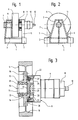
- 1 denotes a machine frame, consisting of a base plate 2, a bearing block 3 with axle holder 4 and two vertically arranged, elastic torque supports 5.
- the machine frame 1 is, for example, a welded structure composed of several parts.
- an axle 11 is fastened in a torsionally rigid manner and also axially fixed.
- a traction sheave 6 for driving conveyor cables 7 of an elevator is rotatably mounted on the protruding end of the axis 11.
- a transmission 8, an electric motor 9, a brake 10 and a rotary encoder 12 are assembled coaxially and overhung on the traction sheave 6, being secured against rotation with two elastic torque supports 5 fastened to the machine frame 1.
- the traction sheave 6 is mounted on the free end of the axle 11 by means of two roller bearings 13, 14, which are seated in a holder 15.
- the roller bearings 13, 14 are held between a shoulder 16 of the axis 11 and a cover plate 17 attached to the axis 11.
- a traction sheave ring 19 is attached to a flange 18 of the handle 15 and is provided on the circumference with a number of grooves symbolized by short lines for the conveyor cables 7 (FIG. 1, 2) of the elevator.
- the flange 18 is screwed to an adapter plate 20 covering the roller bearings 13, 14, to which a first bearing ring 21 is fastened.
- a second bearing ring 23 screwed to a housing 22 of the transmission 8 is pushed over the first bearing ring 21, with rolling elements in the form of balls 24 being arranged between the bearing rings 21, 23.
- the bearing rings 21, 23 and the balls 24 form a bearing, by means of which the gear 8 and with it the electric motor 9 and the brake 10 are rotatably mounted on the traction sheave 6 and are carried by the latter.
- the traction sheave bearing on the axle 11 is sealed with a seal 25 and the housing 22 of the transmission 8 with a seal 26.
- With 27 is attached to the adapter plate 20 driven part, for example a conventional planetary gear.
- the elastic torque support 5 in the example presented consists of a hollow profile 30 with a square cross section, to which a base plate 31 and two coolers 32 are fastened, for example by welding.
- a base plate 31 and two coolers 32 are fastened, for example by welding.
- Bores 33 are provided, the axes of which are aligned and perpendicular to the longitudinal direction of the hollow profile 30.
- two pressure plates are designated, which are guided with cylindrical lugs 35 in the bores 33 of the holder 32.
- Nuts 36 which bear against the holders 32, are screwed onto the threaded cylindrical projections 35.
- damping body 37 are arranged, which consist for example of elastic plastic or rubber.
- two short radial levers 38 offset by 180 ° are welded, which are held between the damping bodies 37, the distance between the pressure plates 34 and thus the degree of damping being adjustable by adjusting the nuts 36.
- the arrangement according to the invention fulfills the function as a resilient and vibration-damped drive in that peak loads and thereby damage to the drive 8, 9 10 are avoided in the event of an emergency stop or interception of the cabin by the safety gear. Due to the concentric and flying attachment of brake 10, motor 9 and gear 8, these modules are easily accessible for maintenance, repairs and replacement.
- an imbalance between the cabin and counterweight resulting from the momentary load conditions is passed via the traction sheave 6, the transmission 8, the motor 9 and the closed brake 10 into the elastic torque arm 5 and is absorbed there as a load torque.
- Due to the elastic design of the torque arm 5, the resulting deflection in one or the other direction of rotation in the event of an imbalance between the cabin and counterweight is a measure of an existing driving or braking load in relation to the cabin.
- This information can be used in the command control for optimizing the call operation and in a drive control for the purpose of compensating for the starting torque in order to prevent the cabin from falling back when starting with a load-related counter torque.
- the starting jerk is reduced for drives with an unregulated three-phase motor.
- gear 8 or drives 8, 9, 10 instead of the planetary gear mentioned, such as, for example, the alternative types which have become known under the product names "Harmonic Drive” and "Cyclo Drive”.
- a hydraulic motor or a compressed air motor can also be used as the motor 9.
- the design of the machine frame 1 is not limited to a welded construction. Designs in cast form or as a modular system with standard parts are also possible.
Abstract
Description
Die Erfindung betrifft eine Antriebsmaschine für Aufzüge, mit einem Getriebe, einem Elektromotor, einer Bremse und einer Treibscheibe, die gleichachsig an einem Maschinengestell angeordnet sind.The invention relates to a drive machine for elevators, with a gear, an electric motor, a brake and a traction sheave, which are arranged coaxially on a machine frame.
Die häufigste Art von Getrieben für Aufzugsantriebe sind Schneckengetriebe, wobei die das Schneckenrad und die Treibscheibe tragende Achse in der Regel zwischen Schneckenrad und Treibscheibe und an ihren Enden gelagert ist. Es werden somit drei Lager mit mindestens drei Wälzlagern benötigt. Mit der DE-OS 43 12 201 ist eine Antriebsmaschine bekannt geworden, bei der die Achse zweifach gelagert ist. Hierbei ist das Schneckenrad fliegend angeordnet, während die Treibscheibe zwischen zwei Lagern eines Gehäuses liegend auf der Achse befestigt ist. Vorstehend beschriebene Getriebe haben den Nachteil, dass Ausrichtungs, bzw. Fluchtungsprobleme auftreten können und durch bei Achsdurchbiegungen entstehende Eingriffsfehler grössere Reibung erzeugt werden kann. Weiterhin können bei kurzen Spitzenbelastungen, wie beispielsweise bei Fang- und Puffertests, Zähne deformiert werden, da das kurzzeitig auftretende Moment das 10-fache des Nennmomentes betragen kann. Die hierbei entstehenden Teilungsfehler müssen durch erhöhten Abrieb in der Zone der deformierten Zähne ausgeglichen werden. Das Gleiche gilt auch für die Anfahrphase des Aufzuges, da bei kurzen Beschleunigungszeiten und hoher Massenträgheit grosse Belastungen auftreten können.The most common type of gears for elevator drives are worm gears, the axis carrying the worm wheel and the traction sheave generally being mounted between the worm wheel and traction sheave and at their ends. Three bearings with at least three roller bearings are therefore required. With DE-OS 43 12 201 a drive machine has become known in which the axle is mounted twice. Here, the worm wheel is arranged on the fly, while the traction sheave is fastened lying on the axle between two bearings of a housing. The above-described gearboxes have the disadvantage that alignment or alignment problems can occur and greater friction can be generated by engagement errors which occur in the event of axle deflections. Furthermore, teeth can be deformed at short peak loads, such as during catch and buffer tests, since the moment that occurs briefly can be 10 times the nominal torque. The resulting pitch errors must be compensated for by increased abrasion in the zone of the deformed teeth. The same applies to the start-up phase of the elevator, since large loads can occur with short acceleration times and high inertia.
Bei einer mit der DE-PS-39 22 272 bekannt gewordenen Antriebsmaschine wird zwecks Verbesserung des vergleichsweise niedrigen Wirkungsgrades von Schneckengetrieben und Erzielung einer kompakteren Bauweise ein Planetengetriebe verwendet, das innerhalb der Treibscheibe plaziert ist. Die Treibscheibe ist mittels zweier Lager drehbar auf einer hohlen, zu beiden Seiten der Treibscheibe abgestützten Lagerachse gelagert, innerhalb welcher eine vom Motor angetriebene Antriebswelle zweifach gelagert ist. Die Antriebswelle weist eine Verzahnung auf, die mit Zwischenrädern im Eingriff ist, welche an Flanschen der Lagerachse drehbar gelagert sind. Die Zwischenräder stehen mit einer Innenverzahnung der Treibscheibe im Eingriff, so dass bei drehender Antriebswelle die Drehbewegung unter Reduktion der Drehzahl auf die Treibscheibe übertragen wird. Das Ende der Antriebswelle ist mit einer Scheibenbremse gekoppelt, die am Maschinengestell befestigt ist. Diese Antriebsmaschine ist relativ kompliziert aufgebaut, wobei der Zusammenbau bzw. die Demontage zwecks Unterhalt oder Reparaturen ziemlich zeitaufwendig ist. Ausserdem muss bei Antrieben mit Mehrfach-Lagerungen mit Ausrichtungs- bzw. Fluchtungsfehlern sowie mit Achsendurchbiegungen gerechnet werden, die sich nachteilig auf das Getriebe auswirken können.In a drive machine which has become known from DE-PS-39 22 272, in order to improve the comparatively low efficiency of worm gears and to achieve a more compact design, a planetary gear is used, which is placed inside the traction sheave. The traction sheave is rotatably mounted on a hollow bearing axis supported on both sides of the traction sheave by means of two bearings, within which a drive shaft driven by the motor is mounted twice. The drive shaft has a toothing which is in engagement with intermediate wheels which are rotatably mounted on flanges of the bearing axis. The idler gears mesh with an internal toothing on the traction sheave, so that when the drive shaft rotates, the rotational movement is transmitted to the traction sheave while reducing the speed. The end of the drive shaft is coupled to a disc brake that is attached to the machine frame. This drive machine is relatively complicated, the assembly or disassembly for maintenance or repairs is quite time consuming. In addition, in the case of drives with multiple bearings, alignment or misalignment as well as axis deflections must be expected, which can have a negative effect on the gearbox.
Der Erfindung liegt die Aufgabe zugrunde eine Antriebsmaschine der eingangs genannten Art vorzuschlagen, welche die vorstehend genannten Nachteile nicht aufweist und wobei insbesondere Eingriffsfehler durch Achsdurchbiegung und Deformationen von Zähnen durch Spitzenbelastungen vermieden werden.The invention is based on the object of proposing a drive machine of the type mentioned at the outset which does not have the disadvantages mentioned above and in particular where errors in engagement due to axle deflection and deformations of teeth due to peak loads are avoided.
Diese Aufgabe wird durch die im Patentanspruch 1 dargelegte Erfindung gelöst. Hierbei ist die Treibscheibe auf einem Ende einer feststehenden Achse drehbar gelagert, die an einem mit dem Maschinengestell verbundenem Träger befestigt ist. Das Getriebe, der Elektromotor und die Bremse sind gleichachsig verlaufend fest miteinander verbunden und fliegend an der Treibscheibe angeordnet, wobei sie mit zwei am Maschinengestell befestigten elastischen Drehmomentenstützen in Verbindung stehen.This object is achieved by the invention set out in
Die mit der Erfindung erzielten Vorteile sind darin zu sehen, dass nur ein Lager benötigt wird, so dass Kosten gespart werden und keine Achsdurchbiegungen mit nachteiligen Auswirkungen auf das Getriebe und andere Maschinenteile entstehen können. Da nur ein Lager vorhanden ist, werden Ausrichtungs- bzw. Fluchtungsprobleme vermieden, die sonst bei nicht zufriedenstellender Lösung zu zusätzlichem Materialverschleiss führen könnten. Mit den elastischen Drehmomentenstützen wird erreicht, dass die bei kurzzeitigen Spitzenbelastungen auftretenden maximalen Drehmomente reduziert und damit Deformationen von Zähnen des Getriebes vermieden werden. Ein weiterer mit den elastischen Drehmomentenstützen erzielbarer Vorteil liegt in der Schwingungsdämpfung der Antriebsmaschine. Die vorgeschlagene fliegende Halterung von Getriebe, Motor und Bremse an der Treibscheibe ergibt ein kompakte, raumsparende Anordnung der Antriebsmaschine, die leicht montierbar ist und weniger Unterhalt und Reparaturen erfordert.The advantages achieved with the invention can be seen in the fact that only one bearing is required, so that costs are saved and no axle deflections with adverse effects on the transmission and other machine parts can occur. Since only one warehouse is available Alignment and alignment problems avoided, which could otherwise lead to additional material wear if the solution is unsatisfactory. With the elastic torque supports it is achieved that the maximum torques occurring during short-term peak loads are reduced and deformations of the teeth of the transmission are avoided. Another advantage that can be achieved with the elastic torque supports is the vibration damping of the drive machine. The proposed flying bracket of gear, motor and brake on the traction sheave results in a compact, space-saving arrangement of the drive machine, which is easy to assemble and requires less maintenance and repairs.
Im folgenden wird die Erfindung anhand eines auf der Zeichnung dargestellten Ausführungsbeispieles näher erläutert. Es zeigen:
- Fig.1
- eine Ansicht der erfindungsgemässen Antriebsmaschine,
- Fig.2
- eine Seitenansicht der Antriebsmaschine gemäss Fig.1,
- Fig.3
- einen Teil-Querschnitt der Antriebsmaschine in gegenüber der Fig.1 vergrössertem Massstab,
- Fig.4
- eine teilweise geschnittene Ansicht einer Drehmomentenstütze der Antriebsmaschine in gegenüber der Fig.1 vergrössertem Massstab und
- Fig.5
- eine Seitenansicht der Drehmomentenstütze gemäss Fig.4.
- Fig. 1
- 2 shows a view of the drive machine according to the invention,
- Fig. 2
- 2 shows a side view of the drive machine according to FIG. 1,
- Fig. 3
- 3 shows a partial cross section of the drive machine on a larger scale than in FIG. 1,
- Fig. 4
- a partially sectioned view of a torque support of the drive machine on a larger scale than in FIG
- Fig. 5
- a side view of the torque arm according to Fig.4.
In den Fig.1 und 2 ist mit 1 ein Maschinengestell bezeichnet, bestehend aus einer Grundplatte 2, einem Lagerbock 3 mit Achshalter 4 sowie zwei vertikal angeordnete, elastische Drehmomentstützen 5. Das Maschinengestell 1 ist beispielsweise eine aus mehreren Teilen zusammengesetzte Schweisskonstruktion. Im Achshalter 4 des Lagerbockes 3 ist eine Achse 11 drehsteif befestigt und auch achsial fixiert.1 and 2, 1 denotes a machine frame, consisting of a
Auf dem herausragenden Ende der Achse 11 ist eine Treibscheibe 6 für den Antrieb von Förderseilen 7 eines Aufzuges drehbar gelagert. Ein Getriebe 8, ein Elektromotor 9, eine Bremse 10 und ein Drehgeber 12 sind gleichachsig zusammengebeaut und fliegend an der Treibscheibe 6 angeordnet, wobei sie gegen Verdrehung gesichert mit zwei am Maschinengestell 1 befestigten elastischen Drehmomentstützen 5 in Verbindung stehen.A
Gemäss Fig.3 ist die Treibscheibe 6 mittels zweier Wälzlager 13,14, die in einer Habe 15 sitzen, auf dem freien Ende der Achse 11 gelagert. Die Wälzlager 13,14 werden hierbei zwischen einer Schulter 16 der Achse 11 und einer an der Achse 11 befestigten Abschlussscheibe 17 gehalten. An einem Flansch 18 der Habe 15 ist ein Treibscheibenkranz 19 befestigt, der am Umfang mit einer Anzahl von durch kurze Striche symbolisierte Rillen für die Förderseile 7 (Fig.1,2) des Aufzuges versehen ist. Der Flansch 18 ist mit einer die Wälzlager 13,14 abdeckenden Adapterplatte 20 verschraubt, an welcher ein erster Lagerring 21 befestigt ist. Ein mit einem Gehäuse 22 des Getriebes 8 verschraubter zweiter Lagerring 23 ist über den ersten Lagerring 21 geschoben, wobei zwischen den Lagerringen 21,23 Wälzkörper in Form von Kugeln 24 angeordnet sind. Die Lagerringe 21,23 und die Kugeln 24 bilden ein Lager, mittels welchem das Getriebe 8 und mit ihm der Elektromotor 9 und die Bremse 10 drehbar an der Treibscheibe 6 gelagert und von dieser getragen werden. Das Treibscheibenlager auf der Achse 11 ist mit einer Dichtung 25 und das Gehäuse 22 des Getriebes 8 mit einer Dichtung 26 abgedichtet. Mit 27 ist ein an der Adapterplatte 20 befestigter Abtriebsteil, beispielsweise eines konventionellen Planetengetriebes bezeichnet.3, the
Nach den Fig.4 und 5 besteht die elastische Drehmomentenstütze 5 im vorgestellten Beispiel aus einem Hohlprofil 30 mit quadratischem Querschnitt, an welchem eine Fussplatte 31 und zwei Kalter 32, beispielsweise durch Schweissen befestigt sind. In den Haltern 32 sind
Bohrungen 33 vorgesehen, deren Achsen fluchten und senkrecht parallel zur Längsrichtung des Hohlprofiles 30 verlaufen. Mit 34 sind zwei Druckplatten bezeichnet, die mit zylindrischen Ansätzen 35 in den Bohrungen 33 der Halter 32 geführt sind. Auf den mit Gewinde versehenen zylindrischen Ansätzen 35 sind Muttern 36 aufgeschraubt, die an den Haltern 32 anliegen. An den Druckplatten 34 sind Dämpfungskörper 37 angeordnet, welche beispielsweise aus elastischem Kunststoff oder Gummi bestehen. Am Gehäuse 22 des Getriebes 8 sind zwei um 180° versetzte, kurze Radialhebel 38 angeschweisst, die zwischen den Dämpfungskörpern 37 gehalten werden, wobei durch Verstellen der Muttern 36 der Abstand zwischen den Druckplatten 34 und damit der Grad der Dämpfung eingestellt werden kann.According to FIGS. 4 and 5, the elastic torque support 5 in the example presented consists of a
Die erfindungsgemässe Anordnung erfüllt die Funktion als federnden und vibrationsgedämpften Antrieb, indem bei Nothalten oder Abfangen der Kabine durch die Fangvorrichtung Spitzenbelastungen und dadurch eventuelle Beschädigungen des Antriebes 8, 9 10 vermieden werden. Durch den konzentrischen und fliegenden Anbau von Bremse 10, Motor 9 und Getriebe 8 sind diese Baugruppen leicht zugänglich für Wartung, Reparaturen und Austausch.The arrangement according to the invention fulfills the function as a resilient and vibration-damped drive in that peak loads and thereby damage to the
Im Ruhezustand der Antriebsmaschine wird ein durch momentane Lastverhältnisse sich ergebendes Ungleichgewicht zwischen Kabine und Gegengewicht über die Treibscheibe 6, das Getriebe 8, den Motor 9 und die geschlossene Bremse 10 in die elastische Drehmomentstütze 5 geleitet und dort als Lastdrehmoment aufgefangen. Durch die elastische Ausführung der Drehmomentstütze 5 ist die sich bei einem Ungleichgewicht zwischen Kabine und Gegengewicht sich ergebende Auslenkung in der einen oder anderen Drehrichtung ein Mass für eine vorhandene treibende oder bremsende Last bezogen auf die Kabine. Diese Information kann in der Kommandosteuerung verwendet werden für eine Optimierung der Rufbedienung und in einer Antriebsregelung zwecks Kompensation des Anfahrdrehmomentes zur Vehütung des Zurücksackens der Kabine beim Anfahren mit lastbedingtem Gegendrehmoment. Bei Antrieben mit ungeregeltem Drehstrommotor wird der Anfahrruck reduziert.In the idle state of the prime mover, an imbalance between the cabin and counterweight resulting from the momentary load conditions is passed via the
Als Getriebe 8 bzw. Antriebe 8, 9, 10 können anstelle des erwähnten Planetengetriebes verschiedene weitere Typen und Bauarten verwendet werden, wie beispielsweise die unter der Produktbezeichnung "Harmonic Drive" und "Cyclo Drive" bekannt gewordenen Alternativtypen.Various other types and designs can be used as the
Als Motor 9 kann in einer weiteren Variante auch ein Hydraulikmotor oder ein Druckluftmotor verwendet werden.In a further variant, a hydraulic motor or a compressed air motor can also be used as the
Die Ausführung des Maschinengestelles 1 beschränkt sich nicht nur auf eine Schweisskonstruktion. Es sind auch Ausführungen in gegossener Form oder als Baukastensystem mit Normteilen möglich.The design of the
Claims (9)
Priority Applications (15)
| Application Number | Priority Date | Filing Date | Title |
|---|---|---|---|
| AT94104765T ATE184573T1 (en) | 1994-03-25 | 1994-03-25 | DRIVE MACHINE FOR ELEVATORS |
| ES94104765T ES2139030T3 (en) | 1994-03-25 | 1994-03-25 | DRIVE MACHINE FOR ELEVATORS. |
| EP94104765A EP0673874B1 (en) | 1994-03-25 | 1994-03-25 | Drive device for elevator |
| DE59408748T DE59408748D1 (en) | 1994-03-25 | 1994-03-25 | Drive machine for lifts |
| TR00276/95A TR28910A (en) | 1994-03-25 | 1995-03-16 | Operating machine for elevators. |
| US08/405,996 US5615864A (en) | 1994-03-25 | 1995-03-17 | Elevator hoist apparatus with torque support device |
| ZA952281A ZA952281B (en) | 1994-03-25 | 1995-03-20 | Driving machine for lifts |
| FI951338A FI106550B (en) | 1994-03-25 | 1995-03-22 | Elevator drive machine |
| CA002145226A CA2145226A1 (en) | 1994-03-25 | 1995-03-22 | Driving machine for lifts |
| JP7064033A JPH07267541A (en) | 1994-03-25 | 1995-03-23 | Driving machine for elevator |
| AU15039/95A AU682788B2 (en) | 1994-03-25 | 1995-03-23 | Driving machine for lifts |
| NO951151A NO951151L (en) | 1994-03-25 | 1995-03-24 | Elevator drive |
| CN95103563A CN1035756C (en) | 1994-03-25 | 1995-03-24 | Driving Machine for lifts |
| BR9501219A BR9501219A (en) | 1994-03-25 | 1995-03-27 | Elevator drive machine |
| HK98112341A HK1011342A1 (en) | 1994-03-25 | 1998-11-26 | Drive device for elevator |
Applications Claiming Priority (1)
| Application Number | Priority Date | Filing Date | Title |
|---|---|---|---|
| EP94104765A EP0673874B1 (en) | 1994-03-25 | 1994-03-25 | Drive device for elevator |
Publications (2)
| Publication Number | Publication Date |
|---|---|
| EP0673874A1 true EP0673874A1 (en) | 1995-09-27 |
| EP0673874B1 EP0673874B1 (en) | 1999-09-15 |
Family
ID=8215809
Family Applications (1)
| Application Number | Title | Priority Date | Filing Date |
|---|---|---|---|
| EP94104765A Expired - Lifetime EP0673874B1 (en) | 1994-03-25 | 1994-03-25 | Drive device for elevator |
Country Status (15)
| Country | Link |
|---|---|
| US (1) | US5615864A (en) |
| EP (1) | EP0673874B1 (en) |
| JP (1) | JPH07267541A (en) |
| CN (1) | CN1035756C (en) |
| AT (1) | ATE184573T1 (en) |
| AU (1) | AU682788B2 (en) |
| BR (1) | BR9501219A (en) |
| CA (1) | CA2145226A1 (en) |
| DE (1) | DE59408748D1 (en) |
| ES (1) | ES2139030T3 (en) |
| FI (1) | FI106550B (en) |
| HK (1) | HK1011342A1 (en) |
| NO (1) | NO951151L (en) |
| TR (1) | TR28910A (en) |
| ZA (1) | ZA952281B (en) |
Cited By (1)
| Publication number | Priority date | Publication date | Assignee | Title |
|---|---|---|---|---|
| DE19630485A1 (en) * | 1996-07-27 | 1998-01-29 | Zahnradfabrik Friedrichshafen | Epicyclic reduction gear for drive mechanism for lift |
Families Citing this family (10)
| Publication number | Priority date | Publication date | Assignee | Title |
|---|---|---|---|---|
| US6601828B2 (en) * | 2001-01-31 | 2003-08-05 | Otis Elevator Company | Elevator hoist machine and related assembly method |
| JP2001039642A (en) * | 1999-08-03 | 2001-02-13 | Teijin Seiki Co Ltd | Elevator |
| JP2001039643A (en) * | 1999-08-03 | 2001-02-13 | Teijin Seiki Co Ltd | Elevator |
| US8201810B2 (en) * | 2009-03-17 | 2012-06-19 | J.R. Clancy, Inc. | Kinematic mount |
| CN101590986B (en) * | 2009-04-30 | 2011-08-03 | 大连华锐股份有限公司 | Method for real-time monitoring of hoisting mechanism of crane |
| GB2485226B (en) * | 2010-11-08 | 2016-12-21 | Siemag Tecberg Gmbh | Torque support for an integrated hoisting machine |
| CN103613038B (en) * | 2013-11-26 | 2017-01-25 | 国家电网公司 | Ground jack and control method thereof |
| ES2695729T3 (en) | 2014-09-12 | 2019-01-10 | Otis Elevator Co | Elevator load weighing system |
| CN106542453A (en) * | 2015-09-17 | 2017-03-29 | 鞍钢股份有限公司 | A kind of overspeed switch braking draw bail and its installation method |
| WO2018185924A1 (en) * | 2017-04-07 | 2018-10-11 | 株式会社日立製作所 | Winding machine and elevator |
Citations (4)
| Publication number | Priority date | Publication date | Assignee | Title |
|---|---|---|---|---|
| JPS54112462A (en) * | 1978-02-22 | 1979-09-03 | Mitsubishi Electric Corp | Wind-up machine for elevator |
| EP0079420A1 (en) * | 1981-10-27 | 1983-05-25 | SICOR S.p.A. | Bearing for the hoist of a passenger or goods elevator car |
| FR2608577A1 (en) * | 1986-12-23 | 1988-06-24 | Kone Oy | DRIVE DEVICE FOR LIFTING APPARATUS |
| US5291966A (en) * | 1991-02-15 | 1994-03-08 | Tokai Rubber Industries, Ltd. | Automobile power plant apparatus |
Family Cites Families (5)
| Publication number | Priority date | Publication date | Assignee | Title |
|---|---|---|---|---|
| SU626633A1 (en) * | 1977-05-17 | 1980-03-05 | Днепропетровский институт инженеров железнодорожного транспорта | Electric arc quenching device |
| FI86289C (en) * | 1988-07-07 | 1992-08-10 | Kone Oy | Elevator machinery |
| DE3840281C2 (en) * | 1988-11-30 | 1997-12-04 | Zahnradfabrik Friedrichshafen | Hoist drive |
| IT1238744B (en) * | 1990-03-07 | 1993-09-03 | Sabiem S P A | GEARMOTOR WITH BODY DIVIDED INTO TWO PIECES WHICH ALSO CLOSE THE STATOR OF THE ELECTRIC MOTOR AND WHICH ARE MUTUAL UNITS WITH COMBINATION AND FIXING ON A VERTICAL IDEAL PLAN |
| ES2053385B1 (en) * | 1992-04-14 | 1997-02-01 | Otis Elevator Comapny | IMPROVEMENTS IN REDUCERS FOR ELEVATOR MACHINES WITH EXTERNAL SUPPORT. |
-
1994
- 1994-03-25 AT AT94104765T patent/ATE184573T1/en not_active IP Right Cessation
- 1994-03-25 DE DE59408748T patent/DE59408748D1/en not_active Expired - Lifetime
- 1994-03-25 ES ES94104765T patent/ES2139030T3/en not_active Expired - Lifetime
- 1994-03-25 EP EP94104765A patent/EP0673874B1/en not_active Expired - Lifetime
-
1995
- 1995-03-16 TR TR00276/95A patent/TR28910A/en unknown
- 1995-03-17 US US08/405,996 patent/US5615864A/en not_active Expired - Fee Related
- 1995-03-20 ZA ZA952281A patent/ZA952281B/en unknown
- 1995-03-22 FI FI951338A patent/FI106550B/en active
- 1995-03-22 CA CA002145226A patent/CA2145226A1/en not_active Abandoned
- 1995-03-23 JP JP7064033A patent/JPH07267541A/en active Pending
- 1995-03-23 AU AU15039/95A patent/AU682788B2/en not_active Ceased
- 1995-03-24 NO NO951151A patent/NO951151L/en unknown
- 1995-03-24 CN CN95103563A patent/CN1035756C/en not_active Expired - Fee Related
- 1995-03-27 BR BR9501219A patent/BR9501219A/en not_active IP Right Cessation
-
1998
- 1998-11-26 HK HK98112341A patent/HK1011342A1/en not_active IP Right Cessation
Patent Citations (4)
| Publication number | Priority date | Publication date | Assignee | Title |
|---|---|---|---|---|
| JPS54112462A (en) * | 1978-02-22 | 1979-09-03 | Mitsubishi Electric Corp | Wind-up machine for elevator |
| EP0079420A1 (en) * | 1981-10-27 | 1983-05-25 | SICOR S.p.A. | Bearing for the hoist of a passenger or goods elevator car |
| FR2608577A1 (en) * | 1986-12-23 | 1988-06-24 | Kone Oy | DRIVE DEVICE FOR LIFTING APPARATUS |
| US5291966A (en) * | 1991-02-15 | 1994-03-08 | Tokai Rubber Industries, Ltd. | Automobile power plant apparatus |
Non-Patent Citations (1)
| Title |
|---|
| PATENT ABSTRACTS OF JAPAN vol. 3, no. 137 (M - 80) 14 November 1979 (1979-11-14) * |
Cited By (1)
| Publication number | Priority date | Publication date | Assignee | Title |
|---|---|---|---|---|
| DE19630485A1 (en) * | 1996-07-27 | 1998-01-29 | Zahnradfabrik Friedrichshafen | Epicyclic reduction gear for drive mechanism for lift |
Also Published As
| Publication number | Publication date |
|---|---|
| US5615864A (en) | 1997-04-01 |
| TR28910A (en) | 1997-07-29 |
| DE59408748D1 (en) | 1999-10-21 |
| FI951338A0 (en) | 1995-03-22 |
| CN1112515A (en) | 1995-11-29 |
| NO951151L (en) | 1995-09-26 |
| ZA952281B (en) | 1996-01-11 |
| AU682788B2 (en) | 1997-10-16 |
| ATE184573T1 (en) | 1999-10-15 |
| CA2145226A1 (en) | 1995-09-26 |
| HK1011342A1 (en) | 1999-07-09 |
| EP0673874B1 (en) | 1999-09-15 |
| AU1503995A (en) | 1995-10-05 |
| NO951151D0 (en) | 1995-03-24 |
| ES2139030T3 (en) | 2000-02-01 |
| FI951338A (en) | 1995-09-26 |
| CN1035756C (en) | 1997-09-03 |
| BR9501219A (en) | 1995-11-14 |
| JPH07267541A (en) | 1995-10-17 |
| FI106550B (en) | 2001-02-28 |
Similar Documents
| Publication | Publication Date | Title |
|---|---|---|
| EP1400479B1 (en) | Driving gear for an elevator and method for installing the driving gear | |
| DE3890561C2 (en) | Revolute coordinator robot (articulated-arm robot, anthropomorphic robot, joint robot) | |
| EP0631068B1 (en) | Arrangement for the rotational drive of an element of a machine or of a subassembly with a work gearing | |
| EP0673874B1 (en) | Drive device for elevator | |
| EP0578069B1 (en) | Driving equipment for a hoist, in particular for a goods or passenger elevator | |
| EP0745553A1 (en) | Lift driving unit | |
| EP0324384B1 (en) | Tensioning device for cable traction drives | |
| EP2089305B1 (en) | Drive for lifts | |
| WO1998021495A1 (en) | Driving mechanism for a stationary transporting device | |
| EP1466858A2 (en) | Industrial truck for high rise shelves with a driving unit | |
| DE19846671A1 (en) | Drive plate brake for self-propelled conveyer systems, especially elevators for people/goods, with increased redundancy has brake units in star formation and equally effective in both directions | |
| EP0792784A1 (en) | Driving device for a railway vehicle and railway vehicle provided with at least one of such driving device | |
| EP1513649B1 (en) | Rack-and-pinion drive with brake unit | |
| DE10136030B4 (en) | Drum drive for an escalator or moving walk | |
| DE10030052A1 (en) | Drive unit for escalators or moving walks | |
| DE19703417A1 (en) | Brake system, in particular a disc brake in the form of a floating caliper, for a motor vehicle | |
| DE3500716C2 (en) | Bearing arrangement | |
| EP1327706B1 (en) | Adaptor arrangement between a motor and a textile machine | |
| DE102022109725A1 (en) | Modular drive machine for an elevator | |
| EP0330133A2 (en) | Device transmitting a torque, and lift installation with such a device | |
| EP1089935A1 (en) | Hoist drive | |
| CH335283A (en) | Escalator | |
| EP0509404A2 (en) | Transporting equipment on cableways for driving haulage cables | |
| DE2825602A1 (en) | LIFTING EQUIPMENT | |
| DE1505310A1 (en) | Unit consisting of motor drive wheel and drive motor |
Legal Events
| Date | Code | Title | Description |
|---|---|---|---|
| PUAI | Public reference made under article 153(3) epc to a published international application that has entered the european phase |
Free format text: ORIGINAL CODE: 0009012 |
|
| AK | Designated contracting states |
Kind code of ref document: A1 Designated state(s): AT BE CH DE DK ES FR GB IT LI NL PT SE |
|
| 17P | Request for examination filed |
Effective date: 19960217 |
|
| GRAG | Despatch of communication of intention to grant |
Free format text: ORIGINAL CODE: EPIDOS AGRA |
|
| 17Q | First examination report despatched |
Effective date: 19981117 |
|
| GRAG | Despatch of communication of intention to grant |
Free format text: ORIGINAL CODE: EPIDOS AGRA |
|
| GRAH | Despatch of communication of intention to grant a patent |
Free format text: ORIGINAL CODE: EPIDOS IGRA |
|
| GRAH | Despatch of communication of intention to grant a patent |
Free format text: ORIGINAL CODE: EPIDOS IGRA |
|
| GRAA | (expected) grant |
Free format text: ORIGINAL CODE: 0009210 |
|
| AK | Designated contracting states |
Kind code of ref document: B1 Designated state(s): AT BE CH DE DK ES FR GB IT LI NL PT SE |
|
| REF | Corresponds to: |
Ref document number: 184573 Country of ref document: AT Date of ref document: 19991015 Kind code of ref document: T |
|
| REG | Reference to a national code |
Ref country code: CH Ref legal event code: EP |
|
| REF | Corresponds to: |
Ref document number: 59408748 Country of ref document: DE Date of ref document: 19991021 |
|
| ITF | It: translation for a ep patent filed |
Owner name: MODIANO & ASSOCIATI S.R.L. |
|
| PG25 | Lapsed in a contracting state [announced via postgrant information from national office to epo] |
Ref country code: DK Free format text: LAPSE BECAUSE OF FAILURE TO SUBMIT A TRANSLATION OF THE DESCRIPTION OR TO PAY THE FEE WITHIN THE PRESCRIBED TIME-LIMIT Effective date: 19991215 |
|
| ET | Fr: translation filed | ||
| REG | Reference to a national code |
Ref country code: ES Ref legal event code: FG2A Ref document number: 2139030 Country of ref document: ES Kind code of ref document: T3 |
|
| REG | Reference to a national code |
Ref country code: PT Ref legal event code: SC4A Free format text: AVAILABILITY OF NATIONAL TRANSLATION Effective date: 19991122 |
|
| PLBE | No opposition filed within time limit |
Free format text: ORIGINAL CODE: 0009261 |
|
| STAA | Information on the status of an ep patent application or granted ep patent |
Free format text: STATUS: NO OPPOSITION FILED WITHIN TIME LIMIT |
|
| 26N | No opposition filed | ||
| REG | Reference to a national code |
Ref country code: GB Ref legal event code: IF02 |
|
| PGFP | Annual fee paid to national office [announced via postgrant information from national office to epo] |
Ref country code: PT Payment date: 20030221 Year of fee payment: 10 |
|
| PGFP | Annual fee paid to national office [announced via postgrant information from national office to epo] |
Ref country code: NL Payment date: 20030228 Year of fee payment: 10 |
|
| PGFP | Annual fee paid to national office [announced via postgrant information from national office to epo] |
Ref country code: SE Payment date: 20030304 Year of fee payment: 10 Ref country code: AT Payment date: 20030304 Year of fee payment: 10 |
|
| PGFP | Annual fee paid to national office [announced via postgrant information from national office to epo] |
Ref country code: BE Payment date: 20030320 Year of fee payment: 10 |
|
| PG25 | Lapsed in a contracting state [announced via postgrant information from national office to epo] |
Ref country code: AT Free format text: LAPSE BECAUSE OF NON-PAYMENT OF DUE FEES Effective date: 20040325 |
|
| PG25 | Lapsed in a contracting state [announced via postgrant information from national office to epo] |
Ref country code: SE Free format text: LAPSE BECAUSE OF NON-PAYMENT OF DUE FEES Effective date: 20040326 |
|
| PG25 | Lapsed in a contracting state [announced via postgrant information from national office to epo] |
Ref country code: BE Free format text: LAPSE BECAUSE OF NON-PAYMENT OF DUE FEES Effective date: 20040331 |
|
| BERE | Be: lapsed |
Owner name: *INVENTIO A.G. Effective date: 20040331 |
|
| PG25 | Lapsed in a contracting state [announced via postgrant information from national office to epo] |
Ref country code: NL Free format text: LAPSE BECAUSE OF NON-PAYMENT OF DUE FEES Effective date: 20041001 |
|
| PG25 | Lapsed in a contracting state [announced via postgrant information from national office to epo] |
Ref country code: PT Free format text: LAPSE BECAUSE OF NON-PAYMENT OF DUE FEES Effective date: 20041015 |
|
| EUG | Se: european patent has lapsed | ||
| REG | Reference to a national code |
Ref country code: PT Ref legal event code: MM4A Free format text: LAPSE DUE TO NON-PAYMENT OF FEES Effective date: 20040930 |
|
| NLV4 | Nl: lapsed or anulled due to non-payment of the annual fee |
Effective date: 20041001 |
|
| PGFP | Annual fee paid to national office [announced via postgrant information from national office to epo] |
Ref country code: CH Payment date: 20120330 Year of fee payment: 19 |
|
| PGFP | Annual fee paid to national office [announced via postgrant information from national office to epo] |
Ref country code: IT Payment date: 20120329 Year of fee payment: 19 |
|
| REG | Reference to a national code |
Ref country code: GB Ref legal event code: 746 Effective date: 20130218 |
|
| REG | Reference to a national code |
Ref country code: DE Ref legal event code: R084 Ref document number: 59408748 Country of ref document: DE Effective date: 20130219 |
|
| PGFP | Annual fee paid to national office [announced via postgrant information from national office to epo] |
Ref country code: GB Payment date: 20130321 Year of fee payment: 20 Ref country code: DE Payment date: 20130321 Year of fee payment: 20 Ref country code: FR Payment date: 20130408 Year of fee payment: 20 |
|
| PGFP | Annual fee paid to national office [announced via postgrant information from national office to epo] |
Ref country code: ES Payment date: 20120327 Year of fee payment: 19 |
|
| REG | Reference to a national code |
Ref country code: CH Ref legal event code: PL |
|
| PG25 | Lapsed in a contracting state [announced via postgrant information from national office to epo] |
Ref country code: CH Free format text: LAPSE BECAUSE OF NON-PAYMENT OF DUE FEES Effective date: 20130331 Ref country code: LI Free format text: LAPSE BECAUSE OF NON-PAYMENT OF DUE FEES Effective date: 20130331 |
|
| PG25 | Lapsed in a contracting state [announced via postgrant information from national office to epo] |
Ref country code: IT Free format text: LAPSE BECAUSE OF NON-PAYMENT OF DUE FEES Effective date: 20130325 |
|
| REG | Reference to a national code |
Ref country code: DE Ref legal event code: R071 Ref document number: 59408748 Country of ref document: DE |
|
| REG | Reference to a national code |
Ref country code: GB Ref legal event code: PE20 Expiry date: 20140324 |
|
| PG25 | Lapsed in a contracting state [announced via postgrant information from national office to epo] |
Ref country code: DE Free format text: LAPSE BECAUSE OF EXPIRATION OF PROTECTION Effective date: 20140326 Ref country code: GB Free format text: LAPSE BECAUSE OF EXPIRATION OF PROTECTION Effective date: 20140324 |
|
| REG | Reference to a national code |
Ref country code: ES Ref legal event code: FD2A Effective date: 20140610 |
|
| PG25 | Lapsed in a contracting state [announced via postgrant information from national office to epo] |
Ref country code: ES Free format text: LAPSE BECAUSE OF NON-PAYMENT OF DUE FEES Effective date: 20130326 |