EP0673449B1 - Automatisierte spinnvorrichtung und verfahren - Google Patents
Automatisierte spinnvorrichtung und verfahren Download PDFInfo
- Publication number
- EP0673449B1 EP0673449B1 EP94930503A EP94930503A EP0673449B1 EP 0673449 B1 EP0673449 B1 EP 0673449B1 EP 94930503 A EP94930503 A EP 94930503A EP 94930503 A EP94930503 A EP 94930503A EP 0673449 B1 EP0673449 B1 EP 0673449B1
- Authority
- EP
- European Patent Office
- Prior art keywords
- sliver
- spinning apparatus
- obtuse
- floor
- vertical portion
- Prior art date
- Legal status (The legal status is an assumption and is not a legal conclusion. Google has not performed a legal analysis and makes no representation as to the accuracy of the status listed.)
- Expired - Lifetime
Links
- 238000009987 spinning Methods 0.000 title claims description 32
- 238000000034 method Methods 0.000 title description 5
- 239000004753 textile Substances 0.000 claims description 12
- 239000000835 fiber Substances 0.000 claims description 7
- 239000000463 material Substances 0.000 claims description 6
- 239000002216 antistatic agent Substances 0.000 claims description 3
- 238000007383 open-end spinning Methods 0.000 description 12
- 230000003750 conditioning effect Effects 0.000 description 2
- 238000010276 construction Methods 0.000 description 2
- 229920000742 Cotton Polymers 0.000 description 1
- 238000010042 air jet spinning Methods 0.000 description 1
- 235000013361 beverage Nutrition 0.000 description 1
- 238000004140 cleaning Methods 0.000 description 1
- 230000001143 conditioned effect Effects 0.000 description 1
- 239000004744 fabric Substances 0.000 description 1
- 238000009940 knitting Methods 0.000 description 1
- 238000012423 maintenance Methods 0.000 description 1
- 238000004519 manufacturing process Methods 0.000 description 1
- 230000004048 modification Effects 0.000 description 1
- 238000012986 modification Methods 0.000 description 1
- 239000004800 polyvinyl chloride Substances 0.000 description 1
- 238000007378 ring spinning Methods 0.000 description 1
- 238000009941 weaving Methods 0.000 description 1
- 238000004804 winding Methods 0.000 description 1
Images

Classifications
-
- D—TEXTILES; PAPER
- D01—NATURAL OR MAN-MADE THREADS OR FIBRES; SPINNING
- D01H—SPINNING OR TWISTING
- D01H4/00—Open-end spinning machines or arrangements for imparting twist to independently moving fibres separated from slivers; Piecing arrangements therefor; Covering endless core threads with fibres by open-end spinning techniques
- D01H4/38—Channels for feeding fibres to the yarn forming region
-
- D—TEXTILES; PAPER
- D01—NATURAL OR MAN-MADE THREADS OR FIBRES; SPINNING
- D01H—SPINNING OR TWISTING
- D01H5/00—Drafting machines or arrangements ; Threading of roving into drafting machine
- D01H5/005—Arrangements for feeding or conveying the slivers to the drafting machine
Definitions
- This invention relates generally to the art of textiles and more particularly to a ringless spinning apparatus combined with a sliver feed tube for feeding sliver to said spinning machine and a plant structure for the spinning of textile fibers into yarn products.
- An example of an open-end spinning apparatus is the Autocoro 240 automatic rotor spinning and winding machine produced and sold by W. Schlafhorst & Co.
- Patent Abstracts of Japan, vol. 15, no. 421 (C-878) corresponding to JP-A-03174032 and US Patent No. 3,469,385 disclose plant structures with the pre-characterising features of claims 1 and 6.
- a ringless spinning apparatus for conditioning textile fibres as defined in the claims 1 and 6.
- this object is accomplished by a plant structure comprising a building structure having first, second and third floors therein, first and second ringless spinning apparatuses located adjacent one another on the first floor, a first sliver feed tube on the second floor for directing sliver from a can located on the second floor to the first ringless spinning apparatus, and a second sliver feed tube extending from the third floor to the second ringless spinning apparatus for directing sliver from a can located on the third floor to the second ringless spinning apparatus.
- Each of the sliver feed tubes has a vertical portion and a straight obtuse portion forming an obtuse angle with the vertical portion a lower end of the vertical portion such that the sliver travels downwardly through the vertical portion and then through the obtuse portion, being characterized in that each of said sliver feed tubes has a horizontal portion following said obtuse portion such that said sliver travels downwardly through said vertical portion through said obtuse portion and then through said horizontal portion.
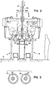
- Figure 1 of the drawings illustrates generally a plant structure 1 having a first floor 3, a second floor 5 and a third floor 7. Located on the first floor or ground floor 3 are first and second open-end spinning apparatuses 11 and 13. Such apparatuses 11 and 13 may be of the type described in U.S. Patent No. 4,939,895 referenced above and which is herewith incorporated by reference and may also be of the type marketed by Schlafhorst as the Autocoro 240.
- Sliver 17 is formed by techniques known in the textile art for the cleaning and opening of textile fibers such as cotton.
- the third floor 7 contains an arrangement similar to the second floor 5, having cans such as 21, also having sliver 23 coiled therein.
- the arrangement in accordance with this invention of utilizing sliver cans on the second and third floors permit the second and third floors to have very tightly controlled temperature and humidity conditions so as to have a sliver properly conditioned for the open end-spinning process. This is achieved by the use of conventional air conditioners 2 located on the second or third floors.
- air conditioners 2 located on the second or third floors.
- the first floor 3, housing the open-end spinning apparatuses 11, 13, is maintained at a different temperature and humidity which is more appropriate for spinning. It has been found to be highly advantageous to separately maintain the sliver at an optimum conditioning temperature while spinning at a different but optimum spinning temperature and humidity.
- the conventional can is normally at a maximum of 0,508 m (twenty inches) by 1,22 m (forty-eight inches) which, does not allow a significant amount of sliver in each can and requires significant and frequent replacement.
- 0,76 m (thirty inch) by 1,27 m (fifty inch) cans 15 can be utilized, thus accommodating more sliver and requiring considerably less frequent changing of the cans 15.
- Sliver feed tubes 31 and 33 extend respectively from the second floor 5 and the third floor 7 to appropriately direct the sliver to open-end spinning apparatuses 11 and 13. As shown in Figure 1, it is seen that the sliver feed tubes pass through the floor structures of the second and third floors 5 and 7. The sliver feed tubes may be immediately adjacent a sliver can or may terminate just above the appropriate floor structure.
- the sliver feed tubes 31 and 33 each respectively include vertical portions 31a, 33a extending vertically downwardly, obtuse portions 31b, 33b extending at an obtuse angle to the vertical portions 31a, 33a, and horizontal end portions 41, 43.
- sliver travels through a vertical portion, an obtuse portion, and a horizontal end portion, at which point the sliver is exposed and fed upwardly to the intake of the spinning apparatus.
- no modification of the spinning apparatus is required and generally the spinning apparatus still receives the sliver in the same manner that it would receive a sliver if it were fed directly from a can thereof placed on the ground floor 3.
- the sliver feed tube utilized in accordance with this invention is generally a smooth, hollow construction and preferably is made transparent so that the movement of the sliver through the tube may be visually observed.
- the tube must be of sufficient diameter to permit the sliver to pass down in a snake-like fashion without significant rubbing on the walls of the tube.
- the tube walls also include an anti-static agent to prevent sticking should contact occur.
- sliver feed tubes 31 and 33 are illustrated in cross-section and have respectively sliver 45 and 47 passing therethrough. It should be noted that the interior surface of the sliver feed tubes 31 and 33 should be very smooth so as to not snag sliver passing therethrough.
- a material possessing the requisite characteristics of smoothness is generally an extruded tubing formed from polyvinyl chloride (PVC), which is the type of material normally utilized for beverage containers.
Landscapes
- Engineering & Computer Science (AREA)
- Mechanical Engineering (AREA)
- Textile Engineering (AREA)
- Spinning Or Twisting Of Yarns (AREA)
Claims (11)
- Ringelfreie Spinnvorrichtung mit Einrichtungen bzw. Mitteln zur Aufnahme eines Faserbands bzw. Spinnbands (23) zum Spinnen desselben in ein Garn, umfassend:ein Spinnband-Zufuhrrohr (33) zum Zuführen eines Spinnbands zu der ringelfreien Spinnvorrichtung (13), wobei das Spinnband (23) einer Spinnbandquelle entstammt, welche zwei Ebenen bzw. Geschoße oberhalb der ringlosen Spinnvorrichtung (13) angeordnet ist;wobei das Spinnband-Zufuhrrohr (33) einen vertikalen Abschnitt bzw. Bereich (33a) und einen geraden, stumpfen bzw. geneigten Abschnitt (33b) aufweist, welcher einen stumpfen Winkel mit dem vertikalen Abschnitt (33a) an einem unteren Ende des vertikalen Abschnitts (33a) ausbildet, so daß das Spinnband (23) nach unten durch den vertikalen Abschnitt (33a) und dann durch den stumpfen bzw. geneigten Abschnitt (33b) verläuft; und
dadurch gekennzeichnet, daß das Spinnband-Zufuhrrohr (33) einen horizontalen Abschnitt (43) beinhaltet, welcher auf den geraden, stumpfen bzw. geneigten Abschnitt (33b) folgt, so daß sich das Spinnband (23) nach unten durch den vertikalen Abschnitt (33a) durch den stumpfen bzw. geneigten Abschnitt (33b) und dann durch den horizontalen Abschnitt (43) bewegt. - Ringelfreie Spinnvorrichtung nach Anspruch 1, worin das Spinnband-Zufuhrrohr (33) aus einem extrudierten Material hergestellt ist.
- Ringelfreie Spinnvorrichtung nach Anspruch 2, worin das extrudierte Material PVC ist.
- Ringelfreie Spinnvorrichtung nach einem der Ansprüche 1 bis 3, worin eine Innenseite des Spinnband-Zufuhrrohrs (33) mit einem antistatischen Mittel beschichtet ist.
- Ringelfreie Spinnvorrichtung nach einem der Ansprüche 1 bis 4, worin das Spinnband-Zufuhrrohr (33) an allen Punkten innerhalb seines Kerns und an seinen beiden Enden ungestört bzw. nicht blockiert ist.
- Fabrik- bzw. Anlagenstruktur für die Behandlung von Textilfasern, um derartige Fasern als Garn auszubilden, umfassend:eine Gebäudestruktur, welche darin erste (3), zweite (5) und dritte (7) Ebenen bzw. Stockwerke aufweist;erste und zweite, ringelfreie Spinnvorrichtungen (11, 13), welche nebeneinander in dem ersten Stock bzw. der ersten Ebene (3) angeordnet sind;ein erstes Spinnband-Zufuhrrohr (31) auf dem zweiten Stockwerk (5) zum Leiten eines Spinnbands (17) von einem Behälter, welcher im zweiten Stockwerk (5) angeordnet ist, zu der ersten, ringelfreien Spinnvorrichtung (11); undein zweites Spinnband-Zufuhrrohr (33), welches sich von dem dritten Stock (7) zu der zweiten, ringelfreien Spinnvorrichtung (13) erstreckt, um ein Spinnband (23) von einem Behälter, welcher in dem dritten Stockwerk (7) angeordnet ist, zu der zweiten, ringelfreien Spinnvorrichtung (13) zu leiten;
wobei jedes der Spinnband-Zufuhrrohre (31, 33) einen vertikalen Abschnitt (31a, 33a) und einen geraden, stumpfen bzw. geneigten Abschnitt (31b, 33b) aufweist, welcher einen stumpfen Winkel mit dem vertikalen Abschnitt (31a, 33a) an einem unteren Ende des vertikalen Abschnitts (31a, 33a) ausbildet, so daß das Spinnband (17, 23) nach unten durch den vertikalen Abschnitt (31a, 33a) und dann durch den stumpfen bzw. geneigten Abschnitt (31b, 33b) läuft bzw. sich bewegt; und
dadurch gekennzeichnet, daß jedes der Spinnband-Zufuhrrohre (31, 33) einen horizontalen Abschnitt (41, 43) aufweist, welcher dem stumpfen bzw. geneigten Abschnitt (31b, 33b) folgt, so daß das Spinnband (17, 23) nach unten durch den vertikalen Abschnitt (31a, 33a), durch den stumpfen bzw. geneigten Abschnitt (31b, 33b) und dann durch den horizontalen Abschnitt (41, 43) läuft bzw. sich bewegt. - Anlagenstruktur zur Behandlung von Textilfasern nach Anspruch 6 worin die ersten und zweiten Spinnband-Zufuhrrohre (31, 33) an allen Punkten innerhalb ihrer Kerne und an ihren entsprechenden Enden nicht blockiert sind.
- Anlagenstruktur zur Behandlung von Textilfasern nach Anspruch 6 oder Anspruch 7, worin eine Innenseite des ersten und zweiten Spinnband-Zufuhrrohrs (31, 33) mit einem antistatischen Mittel beschichtet ist.
- Anlagenstruktur zur Behandung von Textilfasern nach einem der Ansprüche 6 bis 8, worin das erste und zweite Spinnband-Zufuhrrohr (31, 33) aus einem extrudierten Material hergestellt ist.
- Anlagenstruktur zur Behandlung von Textilfasern nach Anspruch 9, worin das extrudierte Material PVC ist.
- Anlagenstruktur zur Behandlung von Textilfasern nach einem der Ansprüche 6 bis 10, worin eine Umgebung einer optimalen Temperatur und Feuchtigkeit zum Spinnen eines Faserbands bzw. Spinnbands (17, 23) in Garn zur Verfügung gestellt wird, wobei die Umgebung in dem zweiten und dritten Stockwerk (5, 7) zur Verfügung gestellt wird.
Priority Applications (1)
| Application Number | Priority Date | Filing Date | Title |
|---|---|---|---|
| EP99203798A EP0985755A1 (de) | 1993-10-08 | 1994-09-30 | Automatisierte Spinnvorrichtung und Verfahren |
Applications Claiming Priority (5)
| Application Number | Priority Date | Filing Date | Title |
|---|---|---|---|
| US08/134,461 US5333440A (en) | 1992-08-21 | 1993-10-08 | Automated spinning apparatus and process |
| US134461 | 1993-10-08 | ||
| US08/217,375 US5465565A (en) | 1992-08-21 | 1994-03-24 | Apparatus and method for delivery of sliver to ringless spinning machine |
| US217375 | 1994-03-24 | ||
| PCT/US1994/011000 WO1995010646A1 (en) | 1993-10-08 | 1994-09-30 | Automated spinning apparatus and process |
Related Child Applications (1)
| Application Number | Title | Priority Date | Filing Date |
|---|---|---|---|
| EP99203798A Division EP0985755A1 (de) | 1993-10-08 | 1994-09-30 | Automatisierte Spinnvorrichtung und Verfahren |
Publications (3)
| Publication Number | Publication Date |
|---|---|
| EP0673449A1 EP0673449A1 (de) | 1995-09-27 |
| EP0673449A4 EP0673449A4 (de) | 1996-04-10 |
| EP0673449B1 true EP0673449B1 (de) | 2000-05-24 |
Family
ID=26832357
Family Applications (1)
| Application Number | Title | Priority Date | Filing Date |
|---|---|---|---|
| EP94930503A Expired - Lifetime EP0673449B1 (de) | 1993-10-08 | 1994-09-30 | Automatisierte spinnvorrichtung und verfahren |
Country Status (4)
| Country | Link |
|---|---|
| US (1) | US5465565A (de) |
| EP (1) | EP0673449B1 (de) |
| DE (1) | DE69424647T2 (de) |
| WO (1) | WO1995010646A1 (de) |
Cited By (1)
| Publication number | Priority date | Publication date | Assignee | Title |
|---|---|---|---|---|
| WO2023187085A3 (de) * | 2022-03-30 | 2023-11-23 | Maschinenfabrik Rieter Ag | Vorrichtung zum pneumatischen verdichten eines verstreckten faserverbandes und verwendung einer feder in der vorrichtung |
Families Citing this family (2)
| Publication number | Priority date | Publication date | Assignee | Title |
|---|---|---|---|---|
| IT1290073B1 (it) * | 1997-03-13 | 1998-10-19 | Vouk Macchine Tessili Spa | Stiratoio con due teste di stiratura in cascata |
| DE10227205A1 (de) * | 2002-06-18 | 2004-01-29 | Matthias Sauerwein | Möbel- und Regalsystem und dessen Verwendung |
Family Cites Families (20)
| Publication number | Priority date | Publication date | Assignee | Title |
|---|---|---|---|---|
| US3070948A (en) * | 1960-01-14 | 1963-01-01 | Tsuzuki Ryohei | Spinning frames |
| NL295932A (de) * | 1962-08-16 | |||
| JPS4422775B1 (de) * | 1966-03-07 | 1969-09-29 | ||
| US3469385A (en) * | 1967-02-15 | 1969-09-30 | Ryohei Tsuzuki | Method for feeding spinning material to spinning machine and its apparatus |
| US3564829A (en) * | 1967-10-19 | 1971-02-23 | Kiyohiro Tsuzuki | Apparatus and method for spinning yarn |
| GB1280456A (en) * | 1968-07-25 | 1972-07-05 | Tmm Research Ltd | Improvements relating to the spinning of textile yarns |
| DE2124923A1 (de) * | 1971-05-19 | 1972-12-07 | Bosch Fernsehanlagen | Verfahren und Einrichtung zur Synchronisierung eines mittels eines Kopfrades auf Band aufgezeichneten Fernsehsignals |
| JPS49134938A (de) * | 1973-05-07 | 1974-12-25 | ||
| US4022007A (en) * | 1974-04-15 | 1977-05-10 | Kabushiki Kaisha Toyoda Jidoshokki Seisakusho | Cooling means for ringless spinning frame |
| DE2507199C2 (de) * | 1975-02-20 | 1986-01-30 | W. Schlafhorst & Co, 4050 Mönchengladbach | Vorrichtung zum Steuern des Anspinnvorgangs bei Rotor-Spinnmaschinen |
| US4098065A (en) * | 1975-05-30 | 1978-07-04 | Fritz Stahlecker | Feeding and opening apparatus for a open-end spinning machine |
| CH655956A5 (de) * | 1981-05-02 | 1986-05-30 | Schlafhorst & Co W | Verfahren und vorrichtung zum offenend-spinnen. |
| DE3402566A1 (de) * | 1984-01-26 | 1985-08-01 | Fritz 7347 Bad Überkingen Stahlecker | Vorrichtung zum oe-friktionsspinnen |
| DE3440816A1 (de) * | 1984-11-08 | 1986-05-15 | Fritz 7347 Bad Überkingen Stahlecker | Zufuehr- und aufloeseeinrichtung fuer eine offenend-spinnvorrichtung |
| IT1220881B (it) * | 1988-05-02 | 1990-06-21 | Cerit Spa | Dispositivo di distribuzione automatica di nastro per macchine di filatura |
| IT1220906B (it) * | 1988-06-29 | 1990-06-21 | Cerit Spa | Procedimento di presa e inserzione nastro in unita' di filatura a fibre libere e dispositivo adottante tale procedimento |
| DE3831637A1 (de) * | 1988-09-17 | 1990-04-05 | Schlafhorst & Co W | Aggregat aus einem oe-spinnautomaten und einer kannenwechselvorrichtung |
| JPH0643649B2 (ja) * | 1989-11-29 | 1994-06-08 | 都築紡績株式会社 | 精紡機に対するスライバーの供給方式 |
| DE4109487A1 (de) * | 1991-03-22 | 1992-09-24 | Fritz Stahlecker | Spinnmaschine |
| DE69323173T2 (de) * | 1992-08-21 | 1999-08-19 | Tns Mills | Automatisierte spinnereianlage |
-
1994
- 1994-03-24 US US08/217,375 patent/US5465565A/en not_active Expired - Fee Related
- 1994-09-30 WO PCT/US1994/011000 patent/WO1995010646A1/en not_active Ceased
- 1994-09-30 EP EP94930503A patent/EP0673449B1/de not_active Expired - Lifetime
- 1994-09-30 DE DE69424647T patent/DE69424647T2/de not_active Expired - Fee Related
Cited By (1)
| Publication number | Priority date | Publication date | Assignee | Title |
|---|---|---|---|---|
| WO2023187085A3 (de) * | 2022-03-30 | 2023-11-23 | Maschinenfabrik Rieter Ag | Vorrichtung zum pneumatischen verdichten eines verstreckten faserverbandes und verwendung einer feder in der vorrichtung |
Also Published As
| Publication number | Publication date |
|---|---|
| EP0673449A1 (de) | 1995-09-27 |
| DE69424647D1 (de) | 2000-06-29 |
| US5465565A (en) | 1995-11-14 |
| DE69424647T2 (de) | 2001-02-08 |
| WO1995010646A1 (en) | 1995-04-20 |
| EP0673449A4 (de) | 1996-04-10 |
Similar Documents
| Publication | Publication Date | Title |
|---|---|---|
| US3391528A (en) | Air handling and cleaning apparatus for machines | |
| US3487619A (en) | Apparatus for high speed drafting | |
| US5651244A (en) | Ring spinning method and a yarn made thereby | |
| US5333440A (en) | Automated spinning apparatus and process | |
| EP0673449B1 (de) | Automatisierte spinnvorrichtung und verfahren | |
| US5638669A (en) | Method and device for manufacturing a twisted yarn by an integrated ring spinning and twisting process | |
| US4856268A (en) | Unwinder arm rotating about a pivot suspended above a two-for-one twisting spindle for unwinding superposed bobbins | |
| US5598692A (en) | Apparatus and method for delivery of sliver to ring spinning machines | |
| JPS6477630A (en) | Air pressure dust removing apparatus for fiber machine | |
| EP0985755A1 (de) | Automatisierte Spinnvorrichtung und Verfahren | |
| CS667385A3 (en) | Machine for open-end friction spinning | |
| EP0673448B1 (de) | Zubehörteil für ein Rohr zum Zuführen eines Faserbandes | |
| US4481766A (en) | Yarn draw off tube for open-end spinning unit | |
| GB2060723A (en) | Winding of yarns from open- end spinners onto common former | |
| KR0140428B1 (ko) | 분리피팅장치 | |
| US3110150A (en) | Yarn spinning machine | |
| EP0417850B1 (de) | Doppeldrahtzwirnmaschinen mit einer Spindel aus zwei Hohlwellen und mit einer beweglichen Wellenkupplung | |
| US3251100A (en) | Drafting system with top and bottom roll cleaning | |
| US5653098A (en) | Ring spinning machine with sliver feed system | |
| US4381638A (en) | Apparatus with a bobbin support member | |
| US5325658A (en) | Spinning machine with false-twisting devices | |
| US5261220A (en) | Spinning machine having a plurality of spinning stations arranged next to one another | |
| US4569189A (en) | Two-for-one yarn twisting spindle assembly having no balloon limitor | |
| CN1087140A (zh) | 纺纱机 | |
| US4938018A (en) | Friction spinning machine |
Legal Events
| Date | Code | Title | Description |
|---|---|---|---|
| PUAI | Public reference made under article 153(3) epc to a published international application that has entered the european phase |
Free format text: ORIGINAL CODE: 0009012 |
|
| 17P | Request for examination filed |
Effective date: 19950619 |
|
| AK | Designated contracting states |
Kind code of ref document: A1 Designated state(s): DE |
|
| A4 | Supplementary search report drawn up and despatched |
Effective date: 19960222 |
|
| AK | Designated contracting states |
Kind code of ref document: A4 Designated state(s): DE |
|
| 17Q | First examination report despatched |
Effective date: 19970903 |
|
| GRAG | Despatch of communication of intention to grant |
Free format text: ORIGINAL CODE: EPIDOS AGRA |
|
| GRAG | Despatch of communication of intention to grant |
Free format text: ORIGINAL CODE: EPIDOS AGRA |
|
| GRAH | Despatch of communication of intention to grant a patent |
Free format text: ORIGINAL CODE: EPIDOS IGRA |
|
| GRAH | Despatch of communication of intention to grant a patent |
Free format text: ORIGINAL CODE: EPIDOS IGRA |
|
| GRAA | (expected) grant |
Free format text: ORIGINAL CODE: 0009210 |
|
| AK | Designated contracting states |
Kind code of ref document: B1 Designated state(s): DE |
|
| REF | Corresponds to: |
Ref document number: 69424647 Country of ref document: DE Date of ref document: 20000629 |
|
| EN | Fr: translation not filed | ||
| PLBE | No opposition filed within time limit |
Free format text: ORIGINAL CODE: 0009261 |
|
| STAA | Information on the status of an ep patent application or granted ep patent |
Free format text: STATUS: NO OPPOSITION FILED WITHIN TIME LIMIT |
|
| 26N | No opposition filed | ||
| PGFP | Annual fee paid to national office [announced via postgrant information from national office to epo] |
Ref country code: DE Payment date: 20011015 Year of fee payment: 8 |
|
| PG25 | Lapsed in a contracting state [announced via postgrant information from national office to epo] |
Ref country code: DE Free format text: LAPSE BECAUSE OF NON-PAYMENT OF DUE FEES Effective date: 20030401 |